EP1526355A1 - Stirnseitige functionale Bilderzeugung mit Verwendung von Mehrfachwellenlängen - Google Patents
Stirnseitige functionale Bilderzeugung mit Verwendung von Mehrfachwellenlängen Download PDFInfo
- Publication number
- EP1526355A1 EP1526355A1 EP04013444A EP04013444A EP1526355A1 EP 1526355 A1 EP1526355 A1 EP 1526355A1 EP 04013444 A EP04013444 A EP 04013444A EP 04013444 A EP04013444 A EP 04013444A EP 1526355 A1 EP1526355 A1 EP 1526355A1
- Authority
- EP
- European Patent Office
- Prior art keywords
- light
- wavelength
- imager
- regions
- under test
- Prior art date
- Legal status (The legal status is an assumption and is not a legal conclusion. Google has not performed a legal analysis and makes no representation as to the accuracy of the status listed.)
- Withdrawn
Links
- 238000003384 imaging method Methods 0.000 title claims abstract description 47
- 238000012360 testing method Methods 0.000 claims abstract description 53
- 239000000463 material Substances 0.000 claims description 17
- 230000000903 blocking effect Effects 0.000 claims description 9
- 238000001914 filtration Methods 0.000 claims description 5
- 238000001514 detection method Methods 0.000 claims description 3
- 238000002059 diagnostic imaging Methods 0.000 claims description 3
- 238000004519 manufacturing process Methods 0.000 claims description 3
- 238000000034 method Methods 0.000 abstract description 16
- 239000000835 fiber Substances 0.000 description 24
- 230000003287 optical effect Effects 0.000 description 21
- 238000010586 diagram Methods 0.000 description 14
- 239000013307 optical fiber Substances 0.000 description 10
- 239000000975 dye Substances 0.000 description 9
- 238000012014 optical coherence tomography Methods 0.000 description 8
- 230000001427 coherent effect Effects 0.000 description 6
- 230000008569 process Effects 0.000 description 6
- 230000000694 effects Effects 0.000 description 5
- 238000012545 processing Methods 0.000 description 5
- 230000005540 biological transmission Effects 0.000 description 4
- 230000008021 deposition Effects 0.000 description 4
- 238000005259 measurement Methods 0.000 description 4
- 230000035945 sensitivity Effects 0.000 description 4
- 238000012935 Averaging Methods 0.000 description 3
- 108010054147 Hemoglobins Proteins 0.000 description 3
- 102000001554 Hemoglobins Human genes 0.000 description 3
- 238000013459 approach Methods 0.000 description 3
- QVGXLLKOCUKJST-UHFFFAOYSA-N atomic oxygen Chemical compound [O] QVGXLLKOCUKJST-UHFFFAOYSA-N 0.000 description 3
- 210000004369 blood Anatomy 0.000 description 3
- 239000008280 blood Substances 0.000 description 3
- 229910052760 oxygen Inorganic materials 0.000 description 3
- 239000001301 oxygen Substances 0.000 description 3
- 229920002120 photoresistant polymer Polymers 0.000 description 3
- 239000004065 semiconductor Substances 0.000 description 3
- 210000001519 tissue Anatomy 0.000 description 3
- 108010064719 Oxyhemoglobins Proteins 0.000 description 2
- 238000000338 in vitro Methods 0.000 description 2
- 238000001727 in vivo Methods 0.000 description 2
- 238000006213 oxygenation reaction Methods 0.000 description 2
- 229920000642 polymer Polymers 0.000 description 2
- XUIMIQQOPSSXEZ-UHFFFAOYSA-N Silicon Chemical compound [Si] XUIMIQQOPSSXEZ-UHFFFAOYSA-N 0.000 description 1
- 206010047571 Visual impairment Diseases 0.000 description 1
- 230000002238 attenuated effect Effects 0.000 description 1
- 210000000988 bone and bone Anatomy 0.000 description 1
- 238000005253 cladding Methods 0.000 description 1
- 230000000295 complement effect Effects 0.000 description 1
- 238000013461 design Methods 0.000 description 1
- 238000001839 endoscopy Methods 0.000 description 1
- 230000005284 excitation Effects 0.000 description 1
- 239000007850 fluorescent dye Substances 0.000 description 1
- 238000012623 in vivo measurement Methods 0.000 description 1
- 229910010272 inorganic material Inorganic materials 0.000 description 1
- 239000011147 inorganic material Substances 0.000 description 1
- 230000001788 irregular Effects 0.000 description 1
- 230000007246 mechanism Effects 0.000 description 1
- 229910052751 metal Inorganic materials 0.000 description 1
- 239000002184 metal Substances 0.000 description 1
- 229910044991 metal oxide Inorganic materials 0.000 description 1
- 150000004706 metal oxides Chemical class 0.000 description 1
- 150000002739 metals Chemical class 0.000 description 1
- 239000000203 mixture Substances 0.000 description 1
- 238000012986 modification Methods 0.000 description 1
- 230000004048 modification Effects 0.000 description 1
- 238000012634 optical imaging Methods 0.000 description 1
- 239000011368 organic material Substances 0.000 description 1
- 239000012860 organic pigment Substances 0.000 description 1
- 230000000399 orthopedic effect Effects 0.000 description 1
- 230000010412 perfusion Effects 0.000 description 1
- 238000000206 photolithography Methods 0.000 description 1
- 230000035790 physiological processes and functions Effects 0.000 description 1
- 239000000049 pigment Substances 0.000 description 1
- 229910052710 silicon Inorganic materials 0.000 description 1
- 239000010703 silicon Substances 0.000 description 1
- 210000003491 skin Anatomy 0.000 description 1
- 238000001228 spectrum Methods 0.000 description 1
- 238000003860 storage Methods 0.000 description 1
- 238000001356 surgical procedure Methods 0.000 description 1
- 230000001360 synchronised effect Effects 0.000 description 1
- 239000010409 thin film Substances 0.000 description 1
- 210000000115 thoracic cavity Anatomy 0.000 description 1
- 238000012546 transfer Methods 0.000 description 1
- 238000013519 translation Methods 0.000 description 1
- 230000014616 translation Effects 0.000 description 1
- 238000002604 ultrasonography Methods 0.000 description 1
- 230000002792 vascular Effects 0.000 description 1
Images


Classifications
-
- A—HUMAN NECESSITIES
- A61—MEDICAL OR VETERINARY SCIENCE; HYGIENE
- A61B—DIAGNOSIS; SURGERY; IDENTIFICATION
- A61B5/00—Measuring for diagnostic purposes; Identification of persons
- A61B5/0059—Measuring for diagnostic purposes; Identification of persons using light, e.g. diagnosis by transillumination, diascopy, fluorescence
- A61B5/0082—Measuring for diagnostic purposes; Identification of persons using light, e.g. diagnosis by transillumination, diascopy, fluorescence adapted for particular medical purposes
- A61B5/0084—Measuring for diagnostic purposes; Identification of persons using light, e.g. diagnosis by transillumination, diascopy, fluorescence adapted for particular medical purposes for introduction into the body, e.g. by catheters
-
- A—HUMAN NECESSITIES
- A61—MEDICAL OR VETERINARY SCIENCE; HYGIENE
- A61B—DIAGNOSIS; SURGERY; IDENTIFICATION
- A61B5/00—Measuring for diagnostic purposes; Identification of persons
- A61B5/0059—Measuring for diagnostic purposes; Identification of persons using light, e.g. diagnosis by transillumination, diascopy, fluorescence
- A61B5/0062—Arrangements for scanning
- A61B5/0066—Optical coherence imaging
-
- G—PHYSICS
- G01—MEASURING; TESTING
- G01N—INVESTIGATING OR ANALYSING MATERIALS BY DETERMINING THEIR CHEMICAL OR PHYSICAL PROPERTIES
- G01N21/00—Investigating or analysing materials by the use of optical means, i.e. using sub-millimetre waves, infrared, visible or ultraviolet light
- G01N21/17—Systems in which incident light is modified in accordance with the properties of the material investigated
- G01N21/25—Colour; Spectral properties, i.e. comparison of effect of material on the light at two or more different wavelengths or wavelength bands
- G01N21/27—Colour; Spectral properties, i.e. comparison of effect of material on the light at two or more different wavelengths or wavelength bands using photo-electric detection ; circuits for computing concentration
-
- G—PHYSICS
- G01—MEASURING; TESTING
- G01N—INVESTIGATING OR ANALYSING MATERIALS BY DETERMINING THEIR CHEMICAL OR PHYSICAL PROPERTIES
- G01N21/00—Investigating or analysing materials by the use of optical means, i.e. using sub-millimetre waves, infrared, visible or ultraviolet light
- G01N21/17—Systems in which incident light is modified in accordance with the properties of the material investigated
- G01N21/47—Scattering, i.e. diffuse reflection
- G01N21/4795—Scattering, i.e. diffuse reflection spatially resolved investigating of object in scattering medium
-
- A—HUMAN NECESSITIES
- A61—MEDICAL OR VETERINARY SCIENCE; HYGIENE
- A61B—DIAGNOSIS; SURGERY; IDENTIFICATION
- A61B5/00—Measuring for diagnostic purposes; Identification of persons
- A61B5/0059—Measuring for diagnostic purposes; Identification of persons using light, e.g. diagnosis by transillumination, diascopy, fluorescence
- A61B5/0071—Measuring for diagnostic purposes; Identification of persons using light, e.g. diagnosis by transillumination, diascopy, fluorescence by measuring fluorescence emission
-
- A—HUMAN NECESSITIES
- A61—MEDICAL OR VETERINARY SCIENCE; HYGIENE
- A61B—DIAGNOSIS; SURGERY; IDENTIFICATION
- A61B5/00—Measuring for diagnostic purposes; Identification of persons
- A61B5/0059—Measuring for diagnostic purposes; Identification of persons using light, e.g. diagnosis by transillumination, diascopy, fluorescence
- A61B5/0082—Measuring for diagnostic purposes; Identification of persons using light, e.g. diagnosis by transillumination, diascopy, fluorescence adapted for particular medical purposes
- A61B5/0084—Measuring for diagnostic purposes; Identification of persons using light, e.g. diagnosis by transillumination, diascopy, fluorescence adapted for particular medical purposes for introduction into the body, e.g. by catheters
- A61B5/0086—Measuring for diagnostic purposes; Identification of persons using light, e.g. diagnosis by transillumination, diascopy, fluorescence adapted for particular medical purposes for introduction into the body, e.g. by catheters using infrared radiation
Definitions
- Embodiments in accordance with the invention generally relate to the field of imaging. More specifically, embodiments in accordance with the invention pertain to functional imaging.
- OCT optical coherence tomography
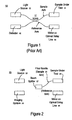
- FIG. 1 is a block diagram of a prior art apparatus 10 that exemplifies a Michelson interferometer.
- Light from light source 12 travels through a single-mode optical fiber to beam splitter 17, typically a 50/50 beam splitter.
- Beam splitter 17 directs a portion of the light along a single-mode optical fiber sample arm to the sample under test 14, with the remainder of the light directed along a single-mode optical fiber reference arm to the mirror 18.
- Sample under test 14 is, for example, a fiber-optic device or human tissue.
- the delay line with a mirror 18 increases the optical length of the reference arm. By moving the mirror back and forth, reflection data can be collected at different depths within sample under test 14.
- Light reflected from sample under test 14 is received by photon detector 16, as is light reflected from the moveable mirror 18.
- Photon detector 16 has just one spatial channel (that is, a single large pixel).
- the sample arm optical fiber is placed at a location in (or on) the sample. A depth scan is obtained at that location. The optical fiber is then moved to an adjacent location and another depth scan is obtained. The process is repeated laterally across the sample, with a depth scan performed at each lateral location. A scan of one line can be referred to as a transverse scan. To create a two-dimensional image of a sample, transverse scans are performed over the area of the sample.
- En-face imaging with a free-space reflectometer and lamp source provides an approach for speeding up the collection of information.
- En-face images are planar images of the sample, captured simultaneously using parallel optical channels in the sample arm of a device like apparatus 10.
- the beam splitter may be a bulk optic free space beam splitter, and the optical signals may propagate in free space within some or all of the arms rather than in optical fibers. Moving the location of the reflector in the reference arm changes the optical depth at which image information is collected. Image information can be collected in two dimensions simultaneously and thus more rapidly. However, lateral scatter of photons from adjacent sample locations can reduce contrast. Thus, en-face imaging, while speeding up image collection, can reduce image quality.
- an imaging system receives light reflected from a sample under test and distinguishes between reflected light at a first wavelength and reflected light at a second wavelength.
- the imaging system can include first regions for detecting light of a first wavelength while blocking light of a second wavelength and second regions for detecting light of the second wavelength.
- Each of the first and second regions may correspond to a respective pixel of a single imager, interleaved in a pattern.
- the first regions may be part of a first imager and the second regions may be part of a second imager. Images at both wavelengths are collected simultaneously.
- En-face images are output using en-face image data corresponding to the first wavelength and en-face image data corresponding to the second wavelength. En-face images can be collected with higher contrast by, for example, taking the difference between the en-face image corresponding to the first wavelength and the en-face image data corresponding to the second wavelength.
- FIG. 2 is a block diagram of an apparatus 20 for en-face imaging of a sample under test 24 using multiple wavelengths of light in one embodiment in accordance with the invention.
- En-face images are planar images of the sample, captured simultaneously.
- En-face image data can be thought of as representing the image generated at a two-dimensional plane that intersects the sample under test 24.
- apparatus 20 includes a light source 22, an imaging system 26, a beam splitter 27, and a mirror on an optical delay line 28.
- Apparatus 20 includes or is coupled to an imaging system 26.
- Apparatus 20 can include other elements in addition to those discussed herein.
- apparatus 20 e.g., light source 22, beam splitter 27 and mirror on optical delay line 28
- a reflectometer or an interferometer such as a Michelson interferometer.
- An overview of these elements e.g., light source 22, a beam splitter 27 and mirror on optical delay line 28
- an interferometer such as a Michelson interferometer.
- Light source 22 is an incoherent light source that transmits light at two or more different wavelengths.
- light source 22 includes a source of white light in combination with a diffuser, as this provides an inexpensive source of incoherent light relative to other types of light sources.
- Use of a white light source may engender the use of filter(s) to eliminate or block wavelengths other than the wavelengths selected for use; refer to Figure 8.
- Other types of lights sources such as edge emitting light emitting diodes (EELEDs) or low coherence superluminescent light emitting diodes (SLDs), can be used.
- Light source 22 can include an aiming beam.
- multiple light sources can be used. Multiple light sources can be combined using beam splitters, fiber combiners, or by focusing one source to transmit through another.
- beam splitter 27 In the embodiment of Figure 2, light from light source 22 travels through free space to beam splitter 27.
- beam splitter 27 is a 50/50 beam splitter.
- beam splitter 27 functions to direct some portion of the light from light source 22 to the sample under test 24, allowing the remainder of the light to pass in free space along the reference arm to the mirror on optical delay line 28. It is appreciated that the function provided by beam splitter 27 can be performed using other mechanisms.
- one or more compact and coherent optical fiber bundles 25 are used to carry light from beam splitter 27 to the sample under test 24.
- the rotation angles between the input and output ends of each of the fiber bundles, the positions of the fibers within the bundles, as well as the magnification in the reference and sample arms, are matched in order to properly register the images collected by each bundle.
- the fiber cores can sample only an array of spots on the sample under test 24. Lateral (or transverse) scanning can be used to scan the cores over the remaining regions of the sample under test. While this image capture process will take longer than the single depth scan of a fully bulk en face reflectometer, it is not nearly as slow as using a single fiber to scan the sample because the extent of the scan translations are limited to the spacing between adjacent fibers.
- Sample under test 24 can be, but is not limited to, a device or human tissue. In the latter case, sample under test 24 can be in vivo or in vitro. For example, in vivo measurements can be performed in conjunction with the coherent optical fiber bundle(s) just described.
- the mirror on optical delay line 28 increases the optical length of the reference arm, thereby increasing the amount of time needed for light to traverse the length of the reference arm.
- reflection data can be collected at different depths within sample under test 24.
- Imaging system 26 generally includes one or more imagers for receiving incident light reflected from the sample under test 24 and for receiving incident light from mirror on optical delay line 28. In general, imaging system 26 functions to generate en-face image data from the two (or more) wavelengths contained in the incident light. In the embodiment of Figure 2, light reflected from sample under test 24 and mirror on optical delay line 28 travels in free space from the beam splitter 27 to imaging system 26.
- imaging system 26 can utilize, for example, a charge-coupled device (CCD) imager or a complementary metal-oxide semiconductor (CMOS) imager.
- CCD charge-coupled device
- CMOS complementary metal-oxide semiconductor
- Imaging system 26 can include other elements, such as but not limited to circuitry and other electronics related to the imaging system, processing capability for processing the image data, display capability for displaying images, storage capability for storing image data or images, and electronics for data transfer.
- imaging system 26 can also include filter(s) to eliminate wavelengths other than the wavelengths selected for use.
- some or all of the free space portions of apparatus 20 are instead fiber-based.
- light reflected from sample under test 24 can be passed through a beam splitter before it reaches the imaging system 26.
- the image data are collected at two (or more) wavelengths.
- imaging system 26 is configured to distinguish between each of the different wavelengths in use, in order to generate high contrast en-face images of the sample under test 24.
- the wavelengths can be selected to augment the contrast in en-face images of the sample under test 24. For example, one wavelength may more readily detect oxyhemoglobin (hemoglobin with bound oxygen) while another wavelength may more readily detect hemoglobin without bound oxygen.
- An en-face image generated using these two wavelengths will include greater contrast between regions of comparatively better or worse blood oxygenation and/or perfusion.
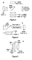
- FIG 3 is a block diagram of an apparatus 30 for en-face imaging in an embodiment in accordance with the invention.
- the imaging system 26 of apparatus 30 includes an imager 32 that is configured to collect image information at two (or more) wavelengths.
- a bulk or large area filter 31 is situated to intercept incident light before the light reaches the imager 32.
- filter 31 is positioned to intercept light as the light is emitted from light source 22.
- Imager 32 is described further in conjunction with Figure 7, and filter 31 is described further in conjunction with Figure 8.
- apparatus 30 of Figure 3 functions as follows for an example based on two wavelengths; however, the invention is not so limited.
- Light source 22 generates light having a range of wavelengths including a first wavelength and a second wavelength. The first and second wavelengths are selectable, as described above.
- the light may be filtered by an optional bulk filter as it is transmitted from light source 22 (e.g., a bulk filter such as that described by Figure 8).
- a portion of the light from light source 22 is directed to sample under test 24 by beam splitter 27, and the remainder of the light is passed to mirror on optical delay line 28.
- the light is essentially broadcast to the sample under test 24 and the mirror on optical delay line 28.
- imager 32 distinguishes between reflected light at the first wavelength and reflected light at the second wavelength, as described further in conjunction with Figure 7.
- Image data corresponding to the first wavelength and image data corresponding to the second wavelength can be used to generate one or more en-face images. For example, separate en-face images may be generated corresponding to the different wavelengths, or a single en-face image may be generated based on the combination of the image data (for example, as described below, image data may be differenced).
- Mirror on optical delay line 28 can then be used to increase the optical length of the reference arm (e.g., a mirror can be moved to a different position), and the process is repeated to generate en-face images at different depths of sample under test 24.
- light from beam splitter 27 is transmitted through fiber bundle 25 to the sample under test 24.
- Light reflected from sample under test 24 is reflected back through fiber bundle 25, then to imager 32 via beam splitter 27.
- Fiber bundle 25 can include one or more coherent optical fiber bundles.
- Light from light source 22 can be passed through an optional lens before the light enters fiber bundle 25.
- a lens can be located between light source 22 and beam splitter 27 and/or between beam splitter 27 and fiber bundle 25, and between fiber bundle 25 and sample under test 24.
- FIG 4 is a block diagram of an apparatus 40 for en-face reflective imaging (not OCT) in one embodiment in accordance with the invention.
- apparatus 40 functions as follows for an example based on two wavelengths; however, the invention is not so limited.
- Light source 22 generates light having multiple wavelengths including a first wavelength and a second wavelength. The first and second wavelengths are selectable, as described above.
- the light may be filtered by an optional bulk filter as it is transmitted from light source 22 (e.g., a bulk filter such as that described by Figure 8).
- the light from light source 22 also may be passed through an optional lens before reaching beam splitter 27 and/or before entering fiber bundle 25.
- Fiber bundle 25 can include one or more coherent optical fiber bundles.
- Imager 32 distinguishes between reflected light at the first wavelength and reflected light at the second wavelength, as described further in conjunction with Figure 7.
- Image data corresponding to the first wavelength and image data corresponding to the second wavelength can be used to generate one or more en-face images. For example, separate en-face images may be generated corresponding to the different wavelengths, or a single en-face image may be generated based on the combination of the image data (for example, as described below, image data may be differenced).
- Figure 4 illustrates an application in which the light source 22 and imager 32 are situated outside of the sample under test. Either or both the light source 22 and imager 32 could be situated within a body (e.g., on a tool such as an endoscope).
- FIG. 5 is a block diagram of an apparatus 50 for en-face reflective imaging (not OCT) in one embodiment in accordance with the invention.
- apparatus 50 functions as follows for an example based on two wavelengths; however, the invention is not so limited.
- Light sources 52 generate light having multiple wavelengths including a first wavelength and a second wavelength. Although light sources 52 is illustrated consisting of two light sources, the invention is not so limited. The first and second wavelengths are selectable, as described above. The light may be filtered by an optional bulk filter as it is transmitted from light sources 52.
- Imager 32 distinguishes between reflected light at the first wavelength and reflected light at the second wavelength, as described further in conjunction with Figure 7.
- Image data corresponding to the first wavelength and image data corresponding to the second wavelength can be used to generate one or more en-face images. For example, separate en-face images may be generated corresponding to the different wavelengths, or a single en-face image may be generated based on the combination of the image data (for example, as described below, image data may be differenced).
- Figure 5 illustrates an application in which the light sources 52 and the imager 32 are situated outside of the sample under test. Either or both the light sources 52 and the imager 32 could be situated within a body (e.g., on a tool such as an endoscope).
- FIG. 6 is a block diagram of an apparatus 60 for en-face transmissive imaging through a sample under test 24 in one embodiment in accordance with the invention.
- apparatus 60 functions as follows for an example based on two wavelengths; however, the invention is not so limited.
- Light source 22 generates light having multiple wavelengths including a first wavelength and a second wavelength. The first and second wavelengths are selectable, as described above.
- the light may be filtered by an optional bulk filter as it is transmitted from light source 22 (e.g., a bulk filter such as that described by Figure 8).
- the light is essentially broadcast onto the sample under test 24.
- the light is transmitted through the sample under test 24, where it is absorbed or attenuated by an amount depending on the characteristics of the material through which the light is passing.
- the transmission of light at each wavelength is a function of the thickness, composition and structure of the skin, tissue, bone, blood and other material through which the light passes.
- imager 32 distinguishes between reflected light at the first wavelength and reflected light at the second wavelength, as described further in conjunction with Figure 7.
- Image data corresponding to the first wavelength and image data corresponding to the second wavelength can be used to generate one or more en-face images. For example, separate en-face images may be generated corresponding to the different wavelengths, or a single en-face image may be generated based on the combination of the image data (for example, as described below, image data may be differenced).
- Figure 6 illustrates an application in which the light source 22 and imager 32 are situated outside of the sample under test. Either or both the light source 22 and imager 32 could be situated within a body (e.g., on a tool such as an endoscope).
- Figure 7 illustrates an imager 32 in one embodiment in accordance with the invention.
- Figure 7 illustrates an example in which two wavelengths ( ⁇ 1 and ⁇ 2 ) and two types of filters are used.
- imager 32 can be configured for more than two wavelengths and/or more than two types of filters.
- Imager 32 is illustrated as a five-by-five array; however, the invention is not limited to those dimensions.
- imager 32 includes a number of first regions and a number of second regions.
- the first regions are for detecting light of the first wavelength ( ⁇ 1 ) and the second regions are for detecting light of the second wavelength ( ⁇ 2 ).
- the first regions include a filter material for blocking (filtering) light of the second wavelength
- the second regions include a filter material for blocking light of the first wavelength.
- the first regions include a filter material for blocking (filtering) light of the second wavelength while detecting light of the first wavelength, while the second regions detect light of both wavelengths (that is, the second regions do not include a filter material for blocking light of the first wavelength).
- a checkerboard pattern is formed on the surface of imager 32; however, other patterns of filter types/filter materials can be used. Patterns other than checkerboard patterns can be used, for example, when more than two types of filters are incorporated into imager 32. Patterns of filter types can be regular or irregular in nature. Also, the different regions of imager 32 (corresponding to the different types of filters and filter materials) are illustrated as being square in shape. However, the present invention is not so limited; that is, regular-shaped regions other than squares as well as irregular-shaped regions can be used. In one embodiment, each region corresponds to a respective pixel of the imager 32. For optical coherence tomography (OCT), pixel sensitivities and the excitation source are selected so that the wavelengths ⁇ 1 and X 2 are present in the spectrum of the light source.
- OCT optical coherence tomography
- Filters can be created as polymers doped with pigments or dyes, interference filters, reflective filters, or absorbing filters made of semiconductors, metals, other inorganic materials, or organic materials, created in any of a number of ways.
- Pigment-doped or dye-doped polymer filters e.g., colored photoresists
- Direct deposition of organic pigments or dyes is also possible.
- Deposition of thin-film dielectric filters is another approach, with proper design so that the dielectric filters are not too thick compared to the lateral dimensions of the pixels. Deposition of semiconductor material with distinct band-edge behavior provides yet another approach.
- the filter materials can be deposited (e.g., layered) as a separate layer of imager 32 (e.g., on top of an underlying layer) using conventional deposition and photolithography processes while still in wafer form, reducing the cost to manufacture. Additionally or alternatively, the filter materials may be mounted as separate elements between the imager 32 and incident light, allowing filtering of light before the light reaches the surface of imager 32. In yet another embodiment, the wavelength sensitivity may be varied within the silicon pixels themselves in a checkerboard pattern, for example.
- Image data collected at two wavelengths can be differenced to compare the responses at the two wavelengths.
- An averaging technique can be applied before the wavelengths are differenced.
- a signal value for a region can be computed for a particular wavelength using signal values from one or more neighboring regions at the same wavelength. For example, an average signal value for ⁇ 2 can be determined for region 76 by averaging the ⁇ 2 signal values for regions 72, 73, 74 and 75. The computed signal value for ⁇ 2 at region 76 can be compared to the measured signal value for ⁇ 1 at region 76.
- gain factors can be applied to the signals generated from the different regions or pixels of imager 32 to account for any differences in sensitivity between the transmission characteristics of each region/pixel.
- Imager 32 can be used in combination with a bulk or large area filter (e.g., optional filter 31 of Figures 3-6), in which case the gain factors are determined considering the effect of filter 31 on the region-by-region (pixel-by-pixel) differences in sensitivity of imager 32.
- image data as just described can be carried out rapidly using an on-board image processing chip, allowing rapid acquisition of successive en-face images.
- imagers at video graphics array (VGA) resolution collection rates of 15 frames per second are commonly achievable.
- adjacent regions e.g., pixels
- image distortions due to bulk optic effects e.g., barrel distortion
- signal values for the same region e.g., pixel
- an en-face image can be generated based on the difference between the two sets of image data.
- an en-face image can be generated based on the set of image data corresponding to the first wavelength, and another en-face image can be generated based on the set of image data corresponding to the second wavelength.
- Figure 8 illustrates transmission versus wavelength characteristics of filter 31 and imager 32 ( Figures 3-6) in accordance with the invention.
- imager 32 includes a number of regions that block a band of light that includes light at a first wavelength and a number of other regions that block a band of light that includes light at a second wavelength.
- imager 32 includes regions that include photoresist filter 1 material to block the band of light that includes light at the first wavelength ( ⁇ 1 ), and regions that include photoresist filter 2 material to block the band of light that includes light at the second wavelength ( ⁇ 2 ).
- Filter 31 includes one or more materials that serve to transmit light only within a narrow wavelength band or bands.
- the filter 31 transmits light in relatively narrow bands (peak 1 and peak 2) around the selected first and second wavelengths ( ⁇ 1 and ⁇ 2 , respectively), blocking or reducing light of wavelengths outside the band.
- the bands are not so narrow as to degrade the depth resolution. Accordingly, the detection of the first and second wavelengths by imager 32 is facilitated.
- Bulk interference filters commonly transmit integral subharmonics of the chosen wavelength.
- a filter designed to transmit 800 nm wavelength light will also transmit 400 nm wavelength light.
- Order-sorting filters can be used as part of the filter 31 to filter out light at wavelengths that are subharmonics of the first and second wavelengths.
- a filter that blocks out light below 800 nm e.g., a filter with a threshold of 600 nm
- FIG 9 is a block diagram of an apparatus 90 for en-face imaging in one embodiment in accordance with the invention.
- apparatus 90 includes a second beam splitter 99 and at least two imagers: first imager 93 and second imager 96.
- the second beam splitter 99 can be a 50/50 beam splitter or a dichroic beam splitter.
- the first imager 93 is for detecting light of a first wavelength
- the second imager 96 is for detecting light of a second wavelength.
- Filters 91 and 95 are optionally included in apparatus 90.
- the second beam splitter 99 is a dichroic beam splitter, then filters 91 and 95 may or may not be used. If the second beam splitter 99 is a 50/50 beam splitter, then filter 91 can be used to block light of the second wavelength from reaching the first imager 93, and filter 95 can be used to block light of the first wavelength from reaching the second imager 96.
- apparatus 90 of Figure 9 functions as follows for an example based on two wavelengths; however, the invention is not so limited.
- Light source 92 generates light having a first and second wavelength. The first and second wavelengths are selectable, as described previously herein.
- the light transmitted by light source 92 may be filtered by an optional bulk filter (e.g., a bulk filter such as that described by Figure 8).
- a bulk filter such as that described by Figure 8 can optionally be placed in other locations within apparatus 90, for example, before beam splitter 99.
- a portion of the light from light source 92 is directed to sample under test 94 by beam splitter 97, and the remainder of the light is passed to mirror on optical delay line 98.
- the light is essentially broadcast to the sample under test 94 and the mirror on optical delay line 98 in free space, although some or all of the free space portions of apparatus 90 can instead be fiber-based.
- beam splitter 99 Light reflected from the sample under test 94 and from mirror on optical delay line 98 is received by beam splitter 99. If beam splitter 99 is a 50/50 beam splitter, half of the reflected light from the sample is directed to the first imager 93 and the remainder of the reflected light is directed to the second imager 96. Filter 91 can be used to block light of the second wavelength from reaching the first imager 93, and filter 95 can be used to block light of the first wavelength from reaching the second imager 96. If beam splitter 99 is a dichroic beam splitter, then one wavelength (e.g., the second wavelength) would be reflected to second imager 96 and other wavelength (e.g., the first wavelength) would be transmitted to first imager 93.
- one wavelength e.g., the second wavelength
- First imager 93 detects light of the first wavelength
- second imager 96 detects light of the second wavelength.
- Image data corresponding to the first wavelength and image data corresponding to the second wavelength can then be used to generate one or more en-face images.
- Image data generated by the two imagers can be differenced.
- the first imager 93 and the second imager 96 are registered spatially and synchronized temporally to capture images at the different wavelengths simultaneously.
- Figure 10 is a flowchart 100 of a method for en-face imaging using multiple wavelengths in one embodiment in accordance with the invention. Although specific steps are disclosed in flowchart 100, such steps are exemplary. That is, embodiments in accordance with the invention are well suited to performing various other steps or variations of the steps recited in flowchart 100. It is appreciated that the steps in flowchart 100 may be performed in an order different than presented, and that not all of the steps in flowchart 100 may be performed.
- en-face images are captured of a sample under test using light that has at least a first and second wavelength.
- the wavelengths to be used for the en-face scanning and imaging can be selected according to the application, the nature of the information that is being collected, the nature of the subject under test, and other factors.
- the source of light can be a broadband source, having wavelengths other than selected wavelengths.
- light transmitted from the light source is filtered to eliminate wavelengths outside the relatively narrow band of the selected wavelengths.
- step 104 light reflected from the sample under test is received in an imaging system that includes a single imager such as imager 32 of Figures 3-6, or multiple imagers such as imagers 93 and 96 of Figure 9.
- the reflected light may be filtered before it reaches the imagers.
- reflected light corresponding to the first wavelength and reflected light corresponding to the second wavelength are separated from each other. That is, for example, an imager such as imager 32 ( Figures 3-6) can have regions for detecting reflected light at the first wavelength and other regions for detecting reflected light at the second wavelength.
- a first imager e.g., imager 93 of Figure 9
- a second imager e.g., imager 96 of Figure 9
- en-face images are output based on the image data generated by the imager or imagers. Separate en-face images can be output for each wavelength in use. Alternatively, the image data for the different wavelengths can be differenced, and the difference between the sets of image data can be used to generate an en-face image.
- embodiments in accordance with the invention allow the rapid collection of en-face data by using a two-dimensional imager. Contrast is increased by providing the capability for simultaneously imaging at multiple wavelengths. Using coherent fiber bundles, in vivo as well as in vitro measurements can be performed.
- the multiple wavelength en-face imagers described herein can be used in a variety of applications, including medical imaging and measurement applications as part of OCT or endoscopy.
- Medical imaging applications include coronary and vascular imaging, oncology, dentistry, neurosurgery, gastroenterology, otolaryngology, dermatology, ophthalmology, thoracic surgery, urology, and orthopedics.
- Measurement applications include cell imaging and metrology in manufacturing.
- Embodiments in accordance with the invention can be particularly advantageous when fluorescent tags are being used.
- a fluorescent medium e.g., a fluorescent dye
- a fluorescent medium e.g., a fluorescent dye
- the dye can be injected and, after the dye has taken effect, simultaneous images can be taken using one wavelength that excites the dye fluorescence and another wavelength that does not excite the fluorescence of that particular dye.
- Differencing of the images can then be performed to highlight regions in the sample under test that fluoresced.
- the patient may be subject to a degree of discomfort and perhaps a degree of risk (e.g., if the patient is anesthetized) while waiting for the dye to take effect.
- the imaging device or the patient may move slightly, causing the before and after images to be offset.
Landscapes
- Health & Medical Sciences (AREA)
- Life Sciences & Earth Sciences (AREA)
- Physics & Mathematics (AREA)
- General Health & Medical Sciences (AREA)
- Pathology (AREA)
- Engineering & Computer Science (AREA)
- Molecular Biology (AREA)
- Surgery (AREA)
- General Physics & Mathematics (AREA)
- Immunology (AREA)
- Analytical Chemistry (AREA)
- Chemical & Material Sciences (AREA)
- Veterinary Medicine (AREA)
- Public Health (AREA)
- Animal Behavior & Ethology (AREA)
- Biochemistry (AREA)
- Medical Informatics (AREA)
- Biophysics (AREA)
- Biomedical Technology (AREA)
- Heart & Thoracic Surgery (AREA)
- Radiology & Medical Imaging (AREA)
- Optics & Photonics (AREA)
- Nuclear Medicine, Radiotherapy & Molecular Imaging (AREA)
- Spectroscopy & Molecular Physics (AREA)
- Theoretical Computer Science (AREA)
- Mathematical Physics (AREA)
- Investigating Or Analysing Materials By Optical Means (AREA)
- Endoscopes (AREA)
Applications Claiming Priority (2)
| Application Number | Priority Date | Filing Date | Title |
|---|---|---|---|
| US690046 | 1985-01-09 | ||
| US10/690,046 US7224468B2 (en) | 2003-10-20 | 2003-10-20 | En-face functional imaging using multiple wavelengths |
Publications (1)
| Publication Number | Publication Date |
|---|---|
| EP1526355A1 true EP1526355A1 (de) | 2005-04-27 |
Family
ID=34394526
Family Applications (1)
| Application Number | Title | Priority Date | Filing Date |
|---|---|---|---|
| EP04013444A Withdrawn EP1526355A1 (de) | 2003-10-20 | 2004-06-08 | Stirnseitige functionale Bilderzeugung mit Verwendung von Mehrfachwellenlängen |
Country Status (3)
| Country | Link |
|---|---|
| US (1) | US7224468B2 (de) |
| EP (1) | EP1526355A1 (de) |
| JP (1) | JP2005125092A (de) |
Cited By (8)
| Publication number | Priority date | Publication date | Assignee | Title |
|---|---|---|---|---|
| EP1595492A1 (de) * | 2004-05-10 | 2005-11-16 | Agilent Technologies Inc. (a Delaware Corporation) | Verfahren und Vorrichtung für wellenlängenabhängiges Abbilden und Detektieren mit einem Hybridfilter |
| WO2008123555A1 (en) | 2007-03-30 | 2008-10-16 | Canon Kabushiki Kaisha | Detection apparatus |
| WO2009076590A3 (en) * | 2007-12-13 | 2009-09-11 | Boston Scientific Scimed, Inc. | Extended spectral sensitivity endoscope system and method of using the same |
| US7737393B2 (en) | 2005-04-21 | 2010-06-15 | Avago Technologies Ecbu Ip (Singapore) Pte. Ltd. | Orientation determination utilizing a cordless device |
| US7796119B2 (en) | 2006-04-03 | 2010-09-14 | Avago Technologies General Ip (Singapore) Pte. Ltd. | Position determination with reference |
| US7812816B2 (en) | 2005-04-21 | 2010-10-12 | Avago Technologies Ecbu Ip (Singapore) Pte. Ltd. | Powerless signal generation for use in conjunction with a powerless position determination device |
| US8130380B2 (en) | 2006-05-24 | 2012-03-06 | Valtion Teknillinen Tutkimuskeskus | Spectrometer and interferometric method |
| CN110672558A (zh) * | 2019-09-24 | 2020-01-10 | 东南大学 | 基于oct技术的神经活动观测方法及系统 |
Families Citing this family (16)
| Publication number | Priority date | Publication date | Assignee | Title |
|---|---|---|---|---|
| WO2006086659A2 (en) * | 2005-02-10 | 2006-08-17 | Massachusetts Institute Of Technology | Column-end fluorescence detection for capillary array electrophoresis |
| WO2007083375A1 (ja) * | 2006-01-19 | 2007-07-26 | Shofu Inc. | 歯科測定用フーリエドメイン光コヒーレンストモグラフィー装置 |
| US8270689B2 (en) * | 2006-09-12 | 2012-09-18 | Carestream Health, Inc. | Apparatus for caries detection |
| JP2008145429A (ja) * | 2006-11-17 | 2008-06-26 | Fujifilm Corp | 光断層画像化装置 |
| US7884814B1 (en) * | 2007-01-12 | 2011-02-08 | Graham Jonathan W | Light emitting display mirrored concealment apparatus and method |
| US7667850B2 (en) * | 2007-06-01 | 2010-02-23 | Raytheon Corporation | Imaging system with low coherence light source |
| JP4987790B2 (ja) * | 2008-04-15 | 2012-07-25 | オリンパスメディカルシステムズ株式会社 | 撮像装置 |
| EP3501384B1 (de) | 2008-05-20 | 2024-07-17 | University Health Network | Verfahren zur bildgebung und überwachung auf fluoreszenzbasis |
| WO2012083967A1 (en) * | 2010-12-21 | 2012-06-28 | 3Shape A/S | Optical system in 3D focus scanner |
| JP6291817B2 (ja) * | 2013-11-29 | 2018-03-14 | セイコーエプソン株式会社 | ラマン分光装置、電子機器、およびラマン分光測定方法 |
| PL3171765T3 (pl) | 2014-07-24 | 2022-01-03 | University Health Network | Zbieranie i analiza danych do celów diagnostycznych |
| CN106361269A (zh) * | 2015-07-23 | 2017-02-01 | 松下知识产权经营株式会社 | 光检测装置以及光检测方法 |
| JP6562857B2 (ja) * | 2016-03-18 | 2019-08-21 | 株式会社吉田製作所 | 光干渉断層画像生成装置及びその使用方法 |
| US10324041B2 (en) * | 2016-12-21 | 2019-06-18 | Abbott Japan Co., Ltd. | Optical imaging system using lateral illumination for digital assays |
| US11047854B2 (en) | 2017-02-06 | 2021-06-29 | Abbott Japan Llc | Methods for reducing noise in signal-generating digital assays |
| CN106990600B (zh) * | 2017-06-07 | 2019-12-06 | 京东方科技集团股份有限公司 | 彩膜基板及其制造方法、显示面板、显示装置 |
Citations (11)
| Publication number | Priority date | Publication date | Assignee | Title |
|---|---|---|---|---|
| US3971065A (en) * | 1975-03-05 | 1976-07-20 | Eastman Kodak Company | Color imaging array |
| US4806776A (en) * | 1980-03-10 | 1989-02-21 | Kley Victor B | Electrical illumination and detecting apparatus |
| US5450205A (en) * | 1993-05-28 | 1995-09-12 | Massachusetts Institute Of Technology | Apparatus and method for real-time measurement of thin film layer thickness and changes thereof |
| WO1997032182A1 (en) * | 1996-02-27 | 1997-09-04 | Massachusetts Institute Of Technology | Method and apparatus for performing optical measurements using a fiber optic imaging guidewire, catheter or endoscope |
| US5943133A (en) * | 1996-12-04 | 1999-08-24 | The Research Foundation Of City College Of New York | System and method for performing selected optical measurements on a sample using a diffraction grating |
| US6320593B1 (en) * | 1999-04-20 | 2001-11-20 | Agilent Technologies, Inc. | Method of fast bi-cubic interpolation of image information |
| US6485413B1 (en) * | 1991-04-29 | 2002-11-26 | The General Hospital Corporation | Methods and apparatus for forward-directed optical scanning instruments |
| US20030020922A1 (en) * | 2001-07-16 | 2003-01-30 | Crowley Robert J. | Systems and methods for processing signals from an interferometer by an ultrasound console |
| US20030137669A1 (en) * | 2001-08-03 | 2003-07-24 | Rollins Andrew M. | Aspects of basic OCT engine technologies for high speed optical coherence tomography and light source and other improvements in optical coherence tomography |
| US6611339B1 (en) * | 2000-06-09 | 2003-08-26 | Massachusetts Institute Of Technology | Phase dispersive tomography |
| WO2005082046A2 (en) * | 2004-02-20 | 2005-09-09 | University Of South Florida | Method of full-color optical coherence tomography |
-
2003
- 2003-10-20 US US10/690,046 patent/US7224468B2/en not_active Expired - Fee Related
-
2004
- 2004-06-08 EP EP04013444A patent/EP1526355A1/de not_active Withdrawn
- 2004-10-15 JP JP2004301135A patent/JP2005125092A/ja active Pending
Patent Citations (11)
| Publication number | Priority date | Publication date | Assignee | Title |
|---|---|---|---|---|
| US3971065A (en) * | 1975-03-05 | 1976-07-20 | Eastman Kodak Company | Color imaging array |
| US4806776A (en) * | 1980-03-10 | 1989-02-21 | Kley Victor B | Electrical illumination and detecting apparatus |
| US6485413B1 (en) * | 1991-04-29 | 2002-11-26 | The General Hospital Corporation | Methods and apparatus for forward-directed optical scanning instruments |
| US5450205A (en) * | 1993-05-28 | 1995-09-12 | Massachusetts Institute Of Technology | Apparatus and method for real-time measurement of thin film layer thickness and changes thereof |
| WO1997032182A1 (en) * | 1996-02-27 | 1997-09-04 | Massachusetts Institute Of Technology | Method and apparatus for performing optical measurements using a fiber optic imaging guidewire, catheter or endoscope |
| US5943133A (en) * | 1996-12-04 | 1999-08-24 | The Research Foundation Of City College Of New York | System and method for performing selected optical measurements on a sample using a diffraction grating |
| US6320593B1 (en) * | 1999-04-20 | 2001-11-20 | Agilent Technologies, Inc. | Method of fast bi-cubic interpolation of image information |
| US6611339B1 (en) * | 2000-06-09 | 2003-08-26 | Massachusetts Institute Of Technology | Phase dispersive tomography |
| US20030020922A1 (en) * | 2001-07-16 | 2003-01-30 | Crowley Robert J. | Systems and methods for processing signals from an interferometer by an ultrasound console |
| US20030137669A1 (en) * | 2001-08-03 | 2003-07-24 | Rollins Andrew M. | Aspects of basic OCT engine technologies for high speed optical coherence tomography and light source and other improvements in optical coherence tomography |
| WO2005082046A2 (en) * | 2004-02-20 | 2005-09-09 | University Of South Florida | Method of full-color optical coherence tomography |
Non-Patent Citations (2)
| Title |
|---|
| LAUDE BLANDINE ET AL: "Full-field optical coherence tomography with thermal light", APPLIED OPTICS, vol. 41, no. 31, 1 November 2002 (2002-11-01), pages 6637 - 6645, XP002990048, DOI: 10.1364/AO.41.006637 * |
| YU LINGFENG ET AL: "Full-color three-dimensional microscopy by wide-field optical coherence tomography", OPTICS EXPRESS, vol. 12, no. 26, 27 December 2004 (2004-12-27), pages 6632 - 6641, XP002506149, DOI: 10.1364/OPEX.12.006632 * |
Cited By (15)
| Publication number | Priority date | Publication date | Assignee | Title |
|---|---|---|---|---|
| US7583863B2 (en) | 2004-05-10 | 2009-09-01 | Avago Technologies General Ip (Singapore) Pte. Ltd. | Method and system for wavelength-dependent imaging and detection using a hybrid filter |
| EP1595492A1 (de) * | 2004-05-10 | 2005-11-16 | Agilent Technologies Inc. (a Delaware Corporation) | Verfahren und Vorrichtung für wellenlängenabhängiges Abbilden und Detektieren mit einem Hybridfilter |
| US8384663B2 (en) | 2005-04-21 | 2013-02-26 | Avago Technologies General Ip (Singapore) Pte. Ltd. | Position determination utilizing a cordless device |
| US7737393B2 (en) | 2005-04-21 | 2010-06-15 | Avago Technologies Ecbu Ip (Singapore) Pte. Ltd. | Orientation determination utilizing a cordless device |
| US7812816B2 (en) | 2005-04-21 | 2010-10-12 | Avago Technologies Ecbu Ip (Singapore) Pte. Ltd. | Powerless signal generation for use in conjunction with a powerless position determination device |
| US7796119B2 (en) | 2006-04-03 | 2010-09-14 | Avago Technologies General Ip (Singapore) Pte. Ltd. | Position determination with reference |
| US8130380B2 (en) | 2006-05-24 | 2012-03-06 | Valtion Teknillinen Tutkimuskeskus | Spectrometer and interferometric method |
| EP2463642A1 (de) * | 2007-03-30 | 2012-06-13 | Canon Kabushiki Kaisha | Detektionsvorrichtung und Abbildungsvorrichtung |
| CN101548175B (zh) * | 2007-03-30 | 2011-04-20 | 佳能株式会社 | 检测装置 |
| WO2008123555A1 (en) | 2007-03-30 | 2008-10-16 | Canon Kabushiki Kaisha | Detection apparatus |
| US8405406B2 (en) | 2007-03-30 | 2013-03-26 | Canon Kabushiki Kaisha | Detecting apparatus and imaging apparatus |
| WO2009076590A3 (en) * | 2007-12-13 | 2009-09-11 | Boston Scientific Scimed, Inc. | Extended spectral sensitivity endoscope system and method of using the same |
| US8280496B2 (en) | 2007-12-13 | 2012-10-02 | Boston Scientific Scimed, Inc. | Extended spectral sensitivity endoscope system and method of using the same |
| CN110672558A (zh) * | 2019-09-24 | 2020-01-10 | 东南大学 | 基于oct技术的神经活动观测方法及系统 |
| CN110672558B (zh) * | 2019-09-24 | 2022-05-10 | 东南大学 | 基于oct技术的神经活动观测方法及系统 |
Also Published As
| Publication number | Publication date |
|---|---|
| JP2005125092A (ja) | 2005-05-19 |
| US20050083536A1 (en) | 2005-04-21 |
| US7224468B2 (en) | 2007-05-29 |
Similar Documents
| Publication | Publication Date | Title |
|---|---|---|
| US7224468B2 (en) | En-face functional imaging using multiple wavelengths | |
| US9918640B2 (en) | Method and device for multi-spectral photonic imaging | |
| Roblyer et al. | Multispectral optical imaging device for in vivo detection of oral neoplasia | |
| US6636755B2 (en) | Method and apparatus for obtaining an optical tomographic image of a sentinel lymph node | |
| US20090131800A1 (en) | Multimodal imaging system for tissue imaging | |
| US11576580B2 (en) | Apparatus, systems and methods for intraoperative imaging | |
| US11803951B2 (en) | High resolution microendoscope employing differential structured illumination and method of using same | |
| US20040089817A1 (en) | Method and apparatus for time resolved optical imaging of biological tissues as part of animals | |
| US20050256403A1 (en) | Method and apparatus for imaging of tissue using multi-wavelength ultrasonic tagging of light | |
| WO2012035170A1 (en) | Optical tissue sectioning using full field optical coherence tomography | |
| WO2005089637A9 (en) | Method and system for tomographic imaging using fluorescent proteins | |
| AU2010222686A1 (en) | Imaging method | |
| Luthman et al. | Bimodal reflectance and fluorescence multispectral endoscopy based on spectrally resolving detector arrays | |
| CN113812928A (zh) | 基于拉曼光谱和光学相干断层成像的多模态成像装置 | |
| CN111031888A (zh) | 用于内窥镜成像的系统和用于处理图像的方法 | |
| JPH09294706A (ja) | 蛍光診断装置 | |
| US20180092519A1 (en) | Infrared fluorescence observation device | |
| JP2009529948A (ja) | 混濁媒体画像形成装置 | |
| KR20180066645A (ko) | 형광 내시경 시스템 | |
| US20080045817A1 (en) | Apparatus and Method for Performing Othogonal Polarized Spectral Imaging (Opsi) | |
| CN101563026B (zh) | 对混浊媒质的成像 | |
| JP4109132B2 (ja) | 蛍光判定装置 | |
| Garcia et al. | A 1600 by 1200, 300 mW, 40 fps multi-spectral imager for near-infrared fluorescence image-guided surgery | |
| JP2006261861A (ja) | 撮像装置 | |
| Vandersmissen et al. | High-resolution InGaAs sensor pushing biomedical infrared optical coherence tomography |
Legal Events
| Date | Code | Title | Description |
|---|---|---|---|
| PUAI | Public reference made under article 153(3) epc to a published international application that has entered the european phase |
Free format text: ORIGINAL CODE: 0009012 |
|
| AK | Designated contracting states |
Kind code of ref document: A1 Designated state(s): AT BE BG CH CY CZ DE DK EE ES FI FR GB GR HU IE IT LI LU MC NL PL PT RO SE SI SK TR |
|
| AX | Request for extension of the european patent |
Extension state: AL HR LT LV MK |
|
| 17P | Request for examination filed |
Effective date: 20050928 |
|
| AKX | Designation fees paid |
Designated state(s): DE FR GB |
|
| 17Q | First examination report despatched |
Effective date: 20061018 |
|
| RAP1 | Party data changed (applicant data changed or rights of an application transferred) |
Owner name: AGILENT TECHNOLOGIES, INC. |
|
| STAA | Information on the status of an ep patent application or granted ep patent |
Free format text: STATUS: THE APPLICATION IS DEEMED TO BE WITHDRAWN |
|
| 18D | Application deemed to be withdrawn |
Effective date: 20090106 |