EP1526271A1 - Abgasrückführventil - Google Patents
Abgasrückführventil Download PDFInfo
- Publication number
- EP1526271A1 EP1526271A1 EP03024508A EP03024508A EP1526271A1 EP 1526271 A1 EP1526271 A1 EP 1526271A1 EP 03024508 A EP03024508 A EP 03024508A EP 03024508 A EP03024508 A EP 03024508A EP 1526271 A1 EP1526271 A1 EP 1526271A1
- Authority
- EP
- European Patent Office
- Prior art keywords
- valve
- exhaust gas
- drive element
- drive
- gas recirculation
- Prior art date
- Legal status (The legal status is an assumption and is not a legal conclusion. Google has not performed a legal analysis and makes no representation as to the accuracy of the status listed.)
- Granted
Links
Images

Classifications
-
- F—MECHANICAL ENGINEERING; LIGHTING; HEATING; WEAPONS; BLASTING
- F02—COMBUSTION ENGINES; HOT-GAS OR COMBUSTION-PRODUCT ENGINE PLANTS
- F02M—SUPPLYING COMBUSTION ENGINES IN GENERAL WITH COMBUSTIBLE MIXTURES OR CONSTITUENTS THEREOF
- F02M26/00—Engine-pertinent apparatus for adding exhaust gases to combustion-air, main fuel or fuel-air mixture, e.g. by exhaust gas recirculation [EGR] systems
- F02M26/52—Systems for actuating EGR valves
- F02M26/53—Systems for actuating EGR valves using electric actuators, e.g. solenoids
- F02M26/54—Rotary actuators, e.g. step motors
-
- F—MECHANICAL ENGINEERING; LIGHTING; HEATING; WEAPONS; BLASTING
- F02—COMBUSTION ENGINES; HOT-GAS OR COMBUSTION-PRODUCT ENGINE PLANTS
- F02M—SUPPLYING COMBUSTION ENGINES IN GENERAL WITH COMBUSTIBLE MIXTURES OR CONSTITUENTS THEREOF
- F02M26/00—Engine-pertinent apparatus for adding exhaust gases to combustion-air, main fuel or fuel-air mixture, e.g. by exhaust gas recirculation [EGR] systems
- F02M26/65—Constructional details of EGR valves
- F02M26/66—Lift valves, e.g. poppet valves
- F02M26/67—Pintles; Spindles; Springs; Bearings; Sealings; Connections to actuators
Definitions
- the invention relates to an exhaust gas recirculation valve after Preamble of claim 1.
- US 4,646,705 describes an exhaust gas recirculation valve in which a disc-shaped valve element eccentrically on a Spindle is attached, so in addition to a lifting motion, the required for opening the valve, a forced Rotary motion takes place, which is used to the effect that Impurities are rubbed off.
- An exhaust gas recirculation valve according to the preamble of claim 1 is known from EP 1 111 227 A2 and sees in this case that a valve element at least at the beginning of the Opening process not only raised but also turned becomes. This can also be done under the Opening process solved impurities and adhesions become.
- the invention is based on the object, an improved Exhaust gas recirculation valve to create, even with more extensive Contaminants work reliably.
- a drive element is through the Rotary drive driven by rotation and constitutes part of the Turn-stroke conversion mechanism.
- Driving element which, as mentioned, by the rotary drive is rotatably driven, by the rotary-hub conversion mechanism as a result of a rotation lifting and lowered.
- this is done by the drive element raising and lowering a valve element around the opening and closing the valve effect.
- the drive element and a valve element in which it is e.g. around a valve lifter with an attached Valve disc can act, connected in such a way that lifting and lowering the drive element or generally a translational movement transferred to the valve element becomes.
- the drive element is connected to the valve element However, at least in the opening direction rotatably connected.
- These rotatable connection can be direct or indirect be provided.
- that can be Valve element when opening together with the drive element but it does not necessarily open when opened rotated. This is a difference and more crucial Advantage to the previously known arrangements in which always forcibly a rotation of the valve element together with the lifting movement took place.
- the measure according to the invention offers the advantage of opening the valve even then possible if a stubborn bonding or Contamination of the valve element in its (rotational) position holds.
- the exhaust gas recirculation valve according to the invention is Drive element at least in the opening direction with respect to the (as a result of adhesive bonds) stuck Rotatable valve element. Therefore, the rotation of the Drive elements even when a seizing of the valve element not prevented, and by the rotary-hub conversion mechanism this rotation becomes a lifting movement converted, so that the valve can be opened trouble-free can. Overall, this allows trouble-free operation be guaranteed.
- inventive Exhaust gas recirculation valve can through the between the Drive element and the valve element acting friction one Setting to do so, with what force a Twisting of the valve element should take place, and from which Threshold a rotation between the drive element and the valve element should be allowed to a To avoid blocking.
- rotatable, direct or indirect connection between Drive element and valve element even at a Exhaust gas recirculation valve may be provided, the one translational drive, for example a solenoid, having instead of the rotary drive.
- a Exhaust gas recirculation valve can also be used to open Bonding to solve a twist of the valve element be provided. This can be done by a rotary-hub conversion mechanism be achieved, the the translational drive movement in an at least slight rotation of the valve element converts. With In other words, a drive element in this case twisted due to the translatory movement.
- the Driving element in all directions, i. also in Closing direction, with respect to the valve element is rotatable.
- the rotating-hub conversion mechanism becomes a helical path preferably, in the at least one fixedly mounted and rotatably mounted roller is arranged.
- the drive element in this preferred case
- a groove in the form of a comparatively short lentline provided.
- a groove flank is supported on the groove arranged in the groove Roll off and thereby causes due to the rotation of the Driving element of a translational movement of the same, the can be used for opening and closing the valve.
- valve element any suitable designs are conceivable, is currently for the inventive Exhaust gas recirculation valve preferred that the valve element a Valve tappet with an attached valve disc is.
- the valve stem is rotatable but axially fixed with connected to the drive element to those described above
- the valve lifter which in this case is part of the rotary-hub conversion mechanism is solid in every way Drive element is connected, and the valve disc with respect the valve stem is rotatable. This can also be a Opening the valve by a stroke even then be realized when the valve disc at its valve seat liable, what in a forced rotation of the Ventiltellers would cause a blockage of the valve.
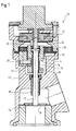
- the exhaust gas recirculation valve 10 shown in FIG. 1 has in its Upper area first, some housing parts and connections for the existing bearing feedback sensors and the like on.
- the description may focus on how the operation as a result of a Rotation of a gear 12 takes place.
- any Drive such as a torque or DC motor is conceivable.
- a so-called Drive element is driven in rotation. In the illustrated Example, this is done via said gear 12, the over two driving pins 46, of which in the figure only one is recognizable, is connected to the drive element 14, the has substantially the shape of a sleeve.
- a Provided spring 48 which is designed as a torsion spring and biases the drive element into the closed state, so that even with a malfunction of the drive a Reliable closure is possible. Acting on this spring it is a spiral or so-called watchmaker's spring, the is deformed at an opening of the valve so that they applying a rotational force in the closing direction.
- a track 16 which forms a section represents a fferline.
- a role 18th Die Roller 18 is on an axis 20 with respect to the housing 22nd fixedly mounted and rotatable about the axis 20.
- the valve element in the case shown the valve tappet 32, with respect to the drive element 14th rotatably mounted. This is done in the example shown by means of the bearing bush 36.
- the rotary-hub conversion mechanism in the form of the screw 16 and role 18 act and lifting the drive member 14 and thus open the valve. This can be a trouble-free opening and overall trouble-free Operation can be realized.
- a seal be.
- the exhaust gas recirculation valve 10 in addition in a perspective view and with more Components, such as a rotary motor 40, shown.
- the rotation of the motor is via different gears 42nd on a gear 12, which is slightly different than the Embodiment of Fig. 1 is arranged, and from there on the drive element 14 transmitted.
- Fig. 2 is in addition to recognize that the drive element 14 for manufacturing reasons can be designed in two parts. This is especially true then as exemplified, realized when by the Divide the drive element 14 and a division of the Screwing 16 is done so that these in other words by the combination of the two parts of the drive element is trained.
- a Torsion spring 44 can be ensured that the valve is biased into a closed position, so too at a fault in the area of the rotary drive 40 a reliable closing done.
Landscapes
- Engineering & Computer Science (AREA)
- Chemical & Material Sciences (AREA)
- Combustion & Propulsion (AREA)
- Mechanical Engineering (AREA)
- General Engineering & Computer Science (AREA)
- Exhaust-Gas Circulating Devices (AREA)
- Mechanically-Actuated Valves (AREA)
- Valve Device For Special Equipments (AREA)
- Valve-Gear Or Valve Arrangements (AREA)
Abstract
Description
- Fig. 1
- eine Schnittdarstellung des erfindungsgemäßen Abgasrückführventils; und
- Fig. 2
- eine perspektivische, teilweise geschnittene Ansicht des erfindungsgemäßen Abgasrückführventils.
Claims (6)
- Abgasrückführventil (10), mit:dadurch gekennzeichnet, dasseinem Drehantrieb (40),einem Dreh-Hub-Umwandlungsmechanismus (14, 18),einem Antriebselement (14), das durch den Drehantrieb (40) drehend antreibbar ist, Teil des Dreh-Hub-Umwandlungsmechanismus (14, 18) ist, und durch diesen infolge einer Drehung translatorisch verschiebbar ist, undeinem Ventilelement (32, 26),
das Antriebselement (14) mit dem Ventilelement (32) zumindest in Öffnungsrichtung drehbar verbunden ist, so dass sich das Ventilelement (32) beim Öffnen mit dem Antriebselement (14) drehen kann, jedoch nicht zwangsweise mit diesem mitgedreht wird. - Abgasrückführventil nach Anspruch 1,
dadurch gekennzeichnet, dass
zwischen dem Antriebselement (14) und dem Ventilelement (32) eine Lagerbuchse (36) vorgesehen ist. - Abgasrückführventil nach Anspruch 1 oder 2,
dadurch gekennzeichnet, dass
das Antriebselement (14) bezüglich des Ventilelements (32) auch in Schließrichtung drehbar ist. - Abgasrückführventil nach zumindest einem der vorangehenden Ansprüche,
dadurch gekennzeichnet, dass
der Dreh-Hub-Umwandlungsmechanismus (14, 18) eine Schraubbahn (16) aufweist, in der zumindest eine feststehend angebrachte, drehbar gelagerte Rolle (18) angeordnet ist. - Abgasrückführventil nach zumindest einem der vorangehenden Ansprüche,
dadurch gekennzeichnet, dass
das Ventilelement ein Ventilstößel (32) mit einem daran angebrachten Ventilteller (26) ist. - Abgasrückführventil nach zumindest einem der vorangehenden Ansprüche,
dadurch gekennzeichnet, dass
das Antriebselement (14) zweiteilig ausgebildet ist.
Priority Applications (7)
| Application Number | Priority Date | Filing Date | Title |
|---|---|---|---|
| DE50307471T DE50307471D1 (de) | 2003-10-24 | 2003-10-24 | Abgasrückführventil |
| AT03024508T ATE364785T1 (de) | 2003-10-24 | 2003-10-24 | Abgasrückführventil |
| EP03024508A EP1526271B1 (de) | 2003-10-24 | 2003-10-24 | Abgasrückführventil |
| ES03024508T ES2288205T3 (es) | 2003-10-24 | 2003-10-24 | Valvula de realimentacion de gases de escape. |
| PT03024508T PT1526271E (pt) | 2003-10-24 | 2003-10-24 | Válvula de recirculação de gases de escape. |
| CNB2004100820990A CN100359153C (zh) | 2003-10-24 | 2004-10-24 | 废气再循环阀 |
| KR1020040085435A KR100677923B1 (ko) | 2003-10-24 | 2004-10-25 | 배기가스 재순환 밸브 |
Applications Claiming Priority (1)
| Application Number | Priority Date | Filing Date | Title |
|---|---|---|---|
| EP03024508A EP1526271B1 (de) | 2003-10-24 | 2003-10-24 | Abgasrückführventil |
Publications (2)
| Publication Number | Publication Date |
|---|---|
| EP1526271A1 true EP1526271A1 (de) | 2005-04-27 |
| EP1526271B1 EP1526271B1 (de) | 2007-06-13 |
Family
ID=34384635
Family Applications (1)
| Application Number | Title | Priority Date | Filing Date |
|---|---|---|---|
| EP03024508A Expired - Lifetime EP1526271B1 (de) | 2003-10-24 | 2003-10-24 | Abgasrückführventil |
Country Status (7)
| Country | Link |
|---|---|
| EP (1) | EP1526271B1 (de) |
| KR (1) | KR100677923B1 (de) |
| CN (1) | CN100359153C (de) |
| AT (1) | ATE364785T1 (de) |
| DE (1) | DE50307471D1 (de) |
| ES (1) | ES2288205T3 (de) |
| PT (1) | PT1526271E (de) |
Cited By (10)
| Publication number | Priority date | Publication date | Assignee | Title |
|---|---|---|---|---|
| EP2172682A1 (de) | 2008-10-06 | 2010-04-07 | Cooper-Standard Automotive (Deutschland) GmbH | Abgasrückführventil |
| FR2937109A1 (fr) * | 2008-10-14 | 2010-04-16 | Valeo Sys Controle Moteur Sas | Vanne egr comportant une tole de support |
| EP2418373A1 (de) | 2010-08-12 | 2012-02-15 | Cooper-Standard Automotive (Deutschland) GmbH | Aktuator und Abgasrückführventil, Wastegate oder variable Turbinengeometrie eines Turboladers mit einem Aktuator |
| EP2418366A1 (de) | 2010-08-12 | 2012-02-15 | Cooper-Standard Automotive (Deutschland) GmbH | Aktuator für ein Wastegate oder eine variable Turbinengeometrie sowie Verwendung eines Aktuators für ein Wastegate oder eine variable Turbinengeometrie |
| WO2012126876A1 (de) * | 2011-03-24 | 2012-09-27 | Pierburg Gmbh | Kfz-abgasrückführungs-ventilanordnung |
| WO2013021133A1 (fr) | 2011-08-08 | 2013-02-14 | Sonceboz Automotive Sa | Dispositif de dosage compact |
| WO2017137384A1 (fr) | 2016-02-09 | 2017-08-17 | Sonceboz Automotive Sa | Vanne de dosage lineaire |
| FR3068424A1 (fr) * | 2017-06-30 | 2019-01-04 | Valeo Systemes De Controle Moteur | Dispositif d'actionnement pour actionneur de controle moteur |
| FR3071898A1 (fr) * | 2017-10-04 | 2019-04-05 | Valeo Systemes De Controle Moteur | Actionneur et vanne de circulation de fluide le comprenant |
| WO2020015812A1 (de) * | 2018-07-16 | 2020-01-23 | Pierburg Gmbh | Ventilanordnung für einen einsatz im kraftfahrzeugbereich und abgasrückführventil |
Families Citing this family (4)
| Publication number | Priority date | Publication date | Assignee | Title |
|---|---|---|---|---|
| FR2947027B1 (fr) * | 2009-06-17 | 2011-07-15 | Valeo Sys Controle Moteur Sas | Dispositif de transformation de mouvement et vanne comportant un tel dispositif |
| CN104165104B (zh) * | 2013-05-16 | 2018-05-11 | 福特汽车萨纳伊股份有限公司 | 排气再循环系统 |
| CN104455678A (zh) * | 2014-11-28 | 2015-03-25 | 长城汽车股份有限公司 | Egr阀驱动机构 |
| CN109611244A (zh) * | 2019-02-01 | 2019-04-12 | 联合汽车电子有限公司 | 废气再循环阀 |
Citations (4)
| Publication number | Priority date | Publication date | Assignee | Title |
|---|---|---|---|---|
| US1454423A (en) * | 1921-03-07 | 1923-05-08 | Continental Engineering Corp | Rotary valve for internal-combustion engines |
| US4346728A (en) * | 1980-07-28 | 1982-08-31 | Anchor/Darling Industries, Inc. | Automated dual mode valve actuator |
| EP1111227A2 (de) * | 1999-12-21 | 2001-06-27 | Siebe Automotive (Deutschland) GmbH | Abgasrückführventil |
| WO2002023032A1 (de) * | 2000-09-12 | 2002-03-21 | Berger Lahr Gmbh & Co. Kg | Zweistufiger elektromotorischer stellantrieb für ein ventil |
Family Cites Families (2)
| Publication number | Priority date | Publication date | Assignee | Title |
|---|---|---|---|---|
| US1451423A (en) * | 1922-05-27 | 1923-04-10 | Royal Typewriter Co Inc | Typewriting machine |
| CN1188098C (zh) * | 1998-10-16 | 2005-02-09 | 皇家菲利浦电子有限公司 | 一种具有吸入室和两个滚筒的按摩器 |
-
2003
- 2003-10-24 EP EP03024508A patent/EP1526271B1/de not_active Expired - Lifetime
- 2003-10-24 AT AT03024508T patent/ATE364785T1/de active
- 2003-10-24 DE DE50307471T patent/DE50307471D1/de not_active Expired - Lifetime
- 2003-10-24 ES ES03024508T patent/ES2288205T3/es not_active Expired - Lifetime
- 2003-10-24 PT PT03024508T patent/PT1526271E/pt unknown
-
2004
- 2004-10-24 CN CNB2004100820990A patent/CN100359153C/zh not_active Expired - Fee Related
- 2004-10-25 KR KR1020040085435A patent/KR100677923B1/ko not_active Expired - Fee Related
Patent Citations (4)
| Publication number | Priority date | Publication date | Assignee | Title |
|---|---|---|---|---|
| US1454423A (en) * | 1921-03-07 | 1923-05-08 | Continental Engineering Corp | Rotary valve for internal-combustion engines |
| US4346728A (en) * | 1980-07-28 | 1982-08-31 | Anchor/Darling Industries, Inc. | Automated dual mode valve actuator |
| EP1111227A2 (de) * | 1999-12-21 | 2001-06-27 | Siebe Automotive (Deutschland) GmbH | Abgasrückführventil |
| WO2002023032A1 (de) * | 2000-09-12 | 2002-03-21 | Berger Lahr Gmbh & Co. Kg | Zweistufiger elektromotorischer stellantrieb für ein ventil |
Cited By (18)
| Publication number | Priority date | Publication date | Assignee | Title |
|---|---|---|---|---|
| US8171919B2 (en) | 2008-10-06 | 2012-05-08 | Cooper-Standard Automotive (Deutschland) Gmbh | Exhaust gas recirculation valve |
| CN101725439A (zh) * | 2008-10-06 | 2010-06-09 | 库珀-标准汽车(德国)股份有限公司 | 废气再循环阀 |
| EP2172682A1 (de) | 2008-10-06 | 2010-04-07 | Cooper-Standard Automotive (Deutschland) GmbH | Abgasrückführventil |
| CN101725439B (zh) * | 2008-10-06 | 2013-08-28 | 库珀-标准汽车(德国)股份有限公司 | 废气再循环阀 |
| FR2937109A1 (fr) * | 2008-10-14 | 2010-04-16 | Valeo Sys Controle Moteur Sas | Vanne egr comportant une tole de support |
| WO2010043328A1 (fr) * | 2008-10-14 | 2010-04-22 | Valeo Systemes De Controle Moteur | Vanne egr comportant une tole de support |
| US9670833B2 (en) | 2010-08-12 | 2017-06-06 | Cooper-Standard Automotive (Deutschland) Gmbh | Actuator and exhaust gas recirculation valve, wastegate or variable turbine geometry device of a turbocharger comprising an actuator |
| EP2418366A1 (de) | 2010-08-12 | 2012-02-15 | Cooper-Standard Automotive (Deutschland) GmbH | Aktuator für ein Wastegate oder eine variable Turbinengeometrie sowie Verwendung eines Aktuators für ein Wastegate oder eine variable Turbinengeometrie |
| EP2418373A1 (de) | 2010-08-12 | 2012-02-15 | Cooper-Standard Automotive (Deutschland) GmbH | Aktuator und Abgasrückführventil, Wastegate oder variable Turbinengeometrie eines Turboladers mit einem Aktuator |
| WO2012126876A1 (de) * | 2011-03-24 | 2012-09-27 | Pierburg Gmbh | Kfz-abgasrückführungs-ventilanordnung |
| JP2014516394A (ja) * | 2011-03-24 | 2014-07-10 | ピールブルク ゲゼルシャフト ミット ベシュレンクテル ハフツング | 自動車排気ガス再循環バルブ装置 |
| US9322365B2 (en) | 2011-03-24 | 2016-04-26 | Pierburg Gmbh | Motor vehicle exhaust-gas recirculation valve arrangement |
| WO2013021133A1 (fr) | 2011-08-08 | 2013-02-14 | Sonceboz Automotive Sa | Dispositif de dosage compact |
| WO2017137384A1 (fr) | 2016-02-09 | 2017-08-17 | Sonceboz Automotive Sa | Vanne de dosage lineaire |
| FR3068424A1 (fr) * | 2017-06-30 | 2019-01-04 | Valeo Systemes De Controle Moteur | Dispositif d'actionnement pour actionneur de controle moteur |
| FR3071898A1 (fr) * | 2017-10-04 | 2019-04-05 | Valeo Systemes De Controle Moteur | Actionneur et vanne de circulation de fluide le comprenant |
| WO2019068991A1 (fr) * | 2017-10-04 | 2019-04-11 | Valeo Systemes De Controle Moteur | Actionneur et vanne de circulation de fluide le comprenant |
| WO2020015812A1 (de) * | 2018-07-16 | 2020-01-23 | Pierburg Gmbh | Ventilanordnung für einen einsatz im kraftfahrzeugbereich und abgasrückführventil |
Also Published As
| Publication number | Publication date |
|---|---|
| KR100677923B1 (ko) | 2007-02-06 |
| CN100359153C (zh) | 2008-01-02 |
| KR20050039684A (ko) | 2005-04-29 |
| EP1526271B1 (de) | 2007-06-13 |
| CN1641203A (zh) | 2005-07-20 |
| PT1526271E (pt) | 2007-06-29 |
| DE50307471D1 (de) | 2007-07-26 |
| ES2288205T3 (es) | 2008-01-01 |
| ATE364785T1 (de) | 2007-07-15 |
Similar Documents
| Publication | Publication Date | Title |
|---|---|---|
| EP1526271B1 (de) | Abgasrückführventil | |
| EP2041387B1 (de) | Drehantrieb für schwenkbare türflügel, insbesondere für fahrzeugtüren | |
| DE102010019344B3 (de) | Antriebseinrichtung | |
| EP2172682B1 (de) | Abgasrückführventil | |
| EP0320490A2 (de) | Absperrorgan | |
| DE3118634C2 (de) | Verstellantrieb mit Schlingfederbremselement in einem Kraftfahrzeug, insbesondere für einen Fensterheber | |
| DE102006031028A1 (de) | Betätigungseinrichtung eines Ventils, insbesondere eines Abasrückführventil | |
| DE102009036872B4 (de) | Türeinheit | |
| WO1987002437A1 (fr) | Vanne a actionnement rapide | |
| EP1257755B1 (de) | Handantrieb für absperrorgane | |
| EP1111227B1 (de) | Abgasrückführventil | |
| EP0856657A2 (de) | Abgasrückführventil für eine Brennkraftmaschine | |
| DE69210384T2 (de) | Stellvorrichtung für ein Drehventil | |
| EP1412636A1 (de) | Starter | |
| EP1526272B1 (de) | Abgasrückführventil | |
| EP1462643A1 (de) | Ventil-Öffnungsmechanismus | |
| DE102004061162A1 (de) | Stellantrieb zur Betätigung einer Armatur | |
| EP2546442A1 (de) | Türband mit Dämpfung | |
| DE2200035C3 (de) | Werkzeug zum Festziehen von Befestigungselementen, beispielsweise Schrauben | |
| EP1245820A1 (de) | Abgasrückführventil | |
| DE10047255C2 (de) | Automatische Dekompressionsvorrichtung für ventilgesteuerte Brennkraftmaschinen | |
| EP0892154B1 (de) | Vorrichtung zum Drehen eines Ventils | |
| DE102004003664B3 (de) | Stellvorrichtung | |
| EP1431495A2 (de) | Elektrohydraulischer Drehflügeltürantrieb | |
| CH647058A5 (de) | Ventil fuer sanitaerarmaturen. |
Legal Events
| Date | Code | Title | Description |
|---|---|---|---|
| PUAI | Public reference made under article 153(3) epc to a published international application that has entered the european phase |
Free format text: ORIGINAL CODE: 0009012 |
|
| AK | Designated contracting states |
Kind code of ref document: A1 Designated state(s): AT BE BG CH CY CZ DE DK EE ES FI FR GB GR HU IE IT LI LU MC NL PT RO SE SI SK TR |
|
| AX | Request for extension of the european patent |
Extension state: AL LT LV MK |
|
| 17P | Request for examination filed |
Effective date: 20051027 |
|
| AKX | Designation fees paid |
Designated state(s): AT BE BG CH CY CZ DE DK EE ES FI FR GB GR HU IE IT LI LU MC NL PT RO SE SI SK TR |
|
| GRAP | Despatch of communication of intention to grant a patent |
Free format text: ORIGINAL CODE: EPIDOSNIGR1 |
|
| GRAS | Grant fee paid |
Free format text: ORIGINAL CODE: EPIDOSNIGR3 |
|
| GRAA | (expected) grant |
Free format text: ORIGINAL CODE: 0009210 |
|
| AK | Designated contracting states |
Kind code of ref document: B1 Designated state(s): AT BE BG CH CY CZ DE DK EE ES FI FR GB GR HU IE IT LI LU MC NL PT RO SE SI SK TR |
|
| REG | Reference to a national code |
Ref country code: GB Ref legal event code: FG4D Free format text: NOT ENGLISH |
|
| REG | Reference to a national code |
Ref country code: PT Ref legal event code: SC4A Free format text: AVAILABILITY OF NATIONAL TRANSLATION Effective date: 20070618 Ref country code: CH Ref legal event code: EP |
|
| GBT | Gb: translation of ep patent filed (gb section 77(6)(a)/1977) |
Effective date: 20070615 |
|
| REG | Reference to a national code |
Ref country code: IE Ref legal event code: FG4D Free format text: LANGUAGE OF EP DOCUMENT: GERMAN |
|
| REF | Corresponds to: |
Ref document number: 50307471 Country of ref document: DE Date of ref document: 20070726 Kind code of ref document: P |
|
| REG | Reference to a national code |
Ref country code: SE Ref legal event code: TRGR |
|
| ET | Fr: translation filed | ||
| NLV1 | Nl: lapsed or annulled due to failure to fulfill the requirements of art. 29p and 29m of the patents act | ||
| REG | Reference to a national code |
Ref country code: ES Ref legal event code: FG2A Ref document number: 2288205 Country of ref document: ES Kind code of ref document: T3 |
|
| PG25 | Lapsed in a contracting state [announced via postgrant information from national office to epo] |
Ref country code: CZ Free format text: LAPSE BECAUSE OF FAILURE TO SUBMIT A TRANSLATION OF THE DESCRIPTION OR TO PAY THE FEE WITHIN THE PRESCRIBED TIME-LIMIT Effective date: 20070613 Ref country code: SI Free format text: LAPSE BECAUSE OF FAILURE TO SUBMIT A TRANSLATION OF THE DESCRIPTION OR TO PAY THE FEE WITHIN THE PRESCRIBED TIME-LIMIT Effective date: 20070613 Ref country code: BG Free format text: LAPSE BECAUSE OF FAILURE TO SUBMIT A TRANSLATION OF THE DESCRIPTION OR TO PAY THE FEE WITHIN THE PRESCRIBED TIME-LIMIT Effective date: 20070913 Ref country code: NL Free format text: LAPSE BECAUSE OF FAILURE TO SUBMIT A TRANSLATION OF THE DESCRIPTION OR TO PAY THE FEE WITHIN THE PRESCRIBED TIME-LIMIT Effective date: 20070613 |
|
| PG25 | Lapsed in a contracting state [announced via postgrant information from national office to epo] |
Ref country code: SK Free format text: LAPSE BECAUSE OF FAILURE TO SUBMIT A TRANSLATION OF THE DESCRIPTION OR TO PAY THE FEE WITHIN THE PRESCRIBED TIME-LIMIT Effective date: 20070613 |
|
| PLBE | No opposition filed within time limit |
Free format text: ORIGINAL CODE: 0009261 |
|
| STAA | Information on the status of an ep patent application or granted ep patent |
Free format text: STATUS: NO OPPOSITION FILED WITHIN TIME LIMIT |
|
| PG25 | Lapsed in a contracting state [announced via postgrant information from national office to epo] |
Ref country code: IT Free format text: LAPSE BECAUSE OF NON-PAYMENT OF DUE FEES Effective date: 20071024 Ref country code: DK Free format text: LAPSE BECAUSE OF FAILURE TO SUBMIT A TRANSLATION OF THE DESCRIPTION OR TO PAY THE FEE WITHIN THE PRESCRIBED TIME-LIMIT Effective date: 20070613 Ref country code: GR Free format text: LAPSE BECAUSE OF FAILURE TO SUBMIT A TRANSLATION OF THE DESCRIPTION OR TO PAY THE FEE WITHIN THE PRESCRIBED TIME-LIMIT Effective date: 20070914 |
|
| 26N | No opposition filed |
Effective date: 20080314 |
|
| PG25 | Lapsed in a contracting state [announced via postgrant information from national office to epo] |
Ref country code: MC Free format text: LAPSE BECAUSE OF NON-PAYMENT OF DUE FEES Effective date: 20071031 Ref country code: RO Free format text: LAPSE BECAUSE OF FAILURE TO SUBMIT A TRANSLATION OF THE DESCRIPTION OR TO PAY THE FEE WITHIN THE PRESCRIBED TIME-LIMIT Effective date: 20070613 |
|
| REG | Reference to a national code |
Ref country code: CH Ref legal event code: PL |
|
| PG25 | Lapsed in a contracting state [announced via postgrant information from national office to epo] |
Ref country code: CH Free format text: LAPSE BECAUSE OF NON-PAYMENT OF DUE FEES Effective date: 20071031 Ref country code: LI Free format text: LAPSE BECAUSE OF NON-PAYMENT OF DUE FEES Effective date: 20071031 |
|
| PG25 | Lapsed in a contracting state [announced via postgrant information from national office to epo] |
Ref country code: EE Free format text: LAPSE BECAUSE OF FAILURE TO SUBMIT A TRANSLATION OF THE DESCRIPTION OR TO PAY THE FEE WITHIN THE PRESCRIBED TIME-LIMIT Effective date: 20070613 |
|
| PG25 | Lapsed in a contracting state [announced via postgrant information from national office to epo] |
Ref country code: FI Free format text: LAPSE BECAUSE OF FAILURE TO SUBMIT A TRANSLATION OF THE DESCRIPTION OR TO PAY THE FEE WITHIN THE PRESCRIBED TIME-LIMIT Effective date: 20070613 |
|
| PG25 | Lapsed in a contracting state [announced via postgrant information from national office to epo] |
Ref country code: CY Free format text: LAPSE BECAUSE OF FAILURE TO SUBMIT A TRANSLATION OF THE DESCRIPTION OR TO PAY THE FEE WITHIN THE PRESCRIBED TIME-LIMIT Effective date: 20070613 |
|
| PG25 | Lapsed in a contracting state [announced via postgrant information from national office to epo] |
Ref country code: LU Free format text: LAPSE BECAUSE OF NON-PAYMENT OF DUE FEES Effective date: 20071024 |
|
| PGRI | Patent reinstated in contracting state [announced from national office to epo] |
Ref country code: IT Effective date: 20090601 |
|
| PG25 | Lapsed in a contracting state [announced via postgrant information from national office to epo] |
Ref country code: TR Free format text: LAPSE BECAUSE OF FAILURE TO SUBMIT A TRANSLATION OF THE DESCRIPTION OR TO PAY THE FEE WITHIN THE PRESCRIBED TIME-LIMIT Effective date: 20070613 Ref country code: HU Free format text: LAPSE BECAUSE OF FAILURE TO SUBMIT A TRANSLATION OF THE DESCRIPTION OR TO PAY THE FEE WITHIN THE PRESCRIBED TIME-LIMIT Effective date: 20071214 |
|
| REG | Reference to a national code |
Ref country code: DE Ref legal event code: R082 Ref document number: 50307471 Country of ref document: DE Representative=s name: HOFFMANN - EITLE, DE |
|
| REG | Reference to a national code |
Ref country code: PT Ref legal event code: PC4A Owner name: HALLA VISTEON CLIMATE CONTROL CORPORATION, KR Effective date: 20141014 |
|
| REG | Reference to a national code |
Ref country code: ES Ref legal event code: PC2A Owner name: HALLA VISTEON CLIMATE CONTROL CORPORATION Effective date: 20141030 |
|
| REG | Reference to a national code |
Ref country code: GB Ref legal event code: 732E Free format text: REGISTERED BETWEEN 20141023 AND 20141029 |
|
| REG | Reference to a national code |
Ref country code: DE Ref legal event code: R081 Ref document number: 50307471 Country of ref document: DE Owner name: HALLA VISTEON CLIMATE CONTROL CORPORATION, KR Free format text: FORMER OWNER: COOPER-STANDARD AUTOMOTIVE (DEUTSCHLAND) GMBH, 89601 SCHELKLINGEN, DE Effective date: 20141015 Ref country code: DE Ref legal event code: R082 Ref document number: 50307471 Country of ref document: DE Representative=s name: HOFFMANN - EITLE PATENT- UND RECHTSANWAELTE PA, DE Effective date: 20141015 Ref country code: DE Ref legal event code: R081 Ref document number: 50307471 Country of ref document: DE Owner name: HANON SYSTEMS, KR Free format text: FORMER OWNER: COOPER-STANDARD AUTOMOTIVE (DEUTSCHLAND) GMBH, 89601 SCHELKLINGEN, DE Effective date: 20141015 |
|
| REG | Reference to a national code |
Ref country code: FR Ref legal event code: TP Owner name: HALLA VISTEON CLIMATE CONTROL CORPORATION, KP Effective date: 20141119 |
|
| REG | Reference to a national code |
Ref country code: AT Ref legal event code: PC Ref document number: 364785 Country of ref document: AT Kind code of ref document: T Owner name: HALLA VISTEON CLIMATE CONTROL CORPORATION, KR Effective date: 20150227 |
|
| REG | Reference to a national code |
Ref country code: ES Ref legal event code: PC2A Owner name: HANON SYSTEMS Effective date: 20160401 |
|
| REG | Reference to a national code |
Ref country code: FR Ref legal event code: PLFP Year of fee payment: 14 |
|
| REG | Reference to a national code |
Ref country code: DE Ref legal event code: R082 Ref document number: 50307471 Country of ref document: DE Representative=s name: HOFFMANN - EITLE PATENT- UND RECHTSANWAELTE PA, DE Ref country code: DE Ref legal event code: R081 Ref document number: 50307471 Country of ref document: DE Owner name: HANON SYSTEMS, KR Free format text: FORMER OWNER: HALLA VISTEON CLIMATE CONTROL CORPORATION, DAEJEON-SI, KR |
|
| REG | Reference to a national code |
Ref country code: FR Ref legal event code: CD Owner name: HANON SYSTEMS, KP Effective date: 20161213 |
|
| REG | Reference to a national code |
Ref country code: FR Ref legal event code: PLFP Year of fee payment: 15 |
|
| REG | Reference to a national code |
Ref country code: FR Ref legal event code: PLFP Year of fee payment: 16 |
|
| REG | Reference to a national code |
Ref country code: AT Ref legal event code: HC Ref document number: 364785 Country of ref document: AT Kind code of ref document: T Owner name: HANON SYSTEMS, KR Effective date: 20190508 |
|
| PGFP | Annual fee paid to national office [announced via postgrant information from national office to epo] |
Ref country code: FR Payment date: 20210915 Year of fee payment: 19 Ref country code: IE Payment date: 20210923 Year of fee payment: 19 Ref country code: IT Payment date: 20210910 Year of fee payment: 19 |
|
| PGFP | Annual fee paid to national office [announced via postgrant information from national office to epo] |
Ref country code: BE Payment date: 20210916 Year of fee payment: 19 Ref country code: SE Payment date: 20210929 Year of fee payment: 19 Ref country code: GB Payment date: 20210915 Year of fee payment: 19 |
|
| PGFP | Annual fee paid to national office [announced via postgrant information from national office to epo] |
Ref country code: ES Payment date: 20211108 Year of fee payment: 19 Ref country code: PT Payment date: 20211025 Year of fee payment: 19 Ref country code: AT Payment date: 20210928 Year of fee payment: 19 Ref country code: DE Payment date: 20210914 Year of fee payment: 19 |
|
| REG | Reference to a national code |
Ref country code: DE Ref legal event code: R119 Ref document number: 50307471 Country of ref document: DE |
|
| REG | Reference to a national code |
Ref country code: SE Ref legal event code: EUG |
|
| REG | Reference to a national code |
Ref country code: AT Ref legal event code: MM01 Ref document number: 364785 Country of ref document: AT Kind code of ref document: T Effective date: 20221024 |
|
| REG | Reference to a national code |
Ref country code: BE Ref legal event code: MM Effective date: 20221031 |
|
| GBPC | Gb: european patent ceased through non-payment of renewal fee |
Effective date: 20221024 |
|
| PG25 | Lapsed in a contracting state [announced via postgrant information from national office to epo] |
Ref country code: PT Free format text: LAPSE BECAUSE OF NON-PAYMENT OF DUE FEES Effective date: 20230424 Ref country code: FR Free format text: LAPSE BECAUSE OF NON-PAYMENT OF DUE FEES Effective date: 20221031 Ref country code: DE Free format text: LAPSE BECAUSE OF NON-PAYMENT OF DUE FEES Effective date: 20230503 Ref country code: AT Free format text: LAPSE BECAUSE OF NON-PAYMENT OF DUE FEES Effective date: 20221024 |
|
| PG25 | Lapsed in a contracting state [announced via postgrant information from national office to epo] |
Ref country code: SE Free format text: LAPSE BECAUSE OF NON-PAYMENT OF DUE FEES Effective date: 20221025 |
|
| PG25 | Lapsed in a contracting state [announced via postgrant information from national office to epo] |
Ref country code: BE Free format text: LAPSE BECAUSE OF NON-PAYMENT OF DUE FEES Effective date: 20221031 |
|
| PG25 | Lapsed in a contracting state [announced via postgrant information from national office to epo] |
Ref country code: IE Free format text: LAPSE BECAUSE OF NON-PAYMENT OF DUE FEES Effective date: 20221024 Ref country code: GB Free format text: LAPSE BECAUSE OF NON-PAYMENT OF DUE FEES Effective date: 20221024 |
|
| REG | Reference to a national code |
Ref country code: ES Ref legal event code: FD2A Effective date: 20231201 |
|
| PG25 | Lapsed in a contracting state [announced via postgrant information from national office to epo] |
Ref country code: ES Free format text: LAPSE BECAUSE OF NON-PAYMENT OF DUE FEES Effective date: 20221025 |
|
| PG25 | Lapsed in a contracting state [announced via postgrant information from national office to epo] |
Ref country code: PT Free format text: LAPSE BECAUSE OF EXPIRATION OF PROTECTION Effective date: 20231103 Ref country code: ES Free format text: LAPSE BECAUSE OF NON-PAYMENT OF DUE FEES Effective date: 20221025 |
|
| PG25 | Lapsed in a contracting state [announced via postgrant information from national office to epo] |
Ref country code: PT Free format text: LAPSE BECAUSE OF NON-PAYMENT OF DUE FEES Effective date: 20221024 |
|
| PG25 | Lapsed in a contracting state [announced via postgrant information from national office to epo] |
Ref country code: PT Free format text: LAPSE BECAUSE OF NON-PAYMENT OF DUE FEES Effective date: 20221024 |
|
| PG25 | Lapsed in a contracting state [announced via postgrant information from national office to epo] |
Ref country code: IT Free format text: LAPSE BECAUSE OF NON-PAYMENT OF DUE FEES Effective date: 20221024 |