EP1526064B1 - Scooter type motorcycle - Google Patents
Scooter type motorcycle Download PDFInfo
- Publication number
- EP1526064B1 EP1526064B1 EP04024953.4A EP04024953A EP1526064B1 EP 1526064 B1 EP1526064 B1 EP 1526064B1 EP 04024953 A EP04024953 A EP 04024953A EP 1526064 B1 EP1526064 B1 EP 1526064B1
- Authority
- EP
- European Patent Office
- Prior art keywords
- reservoir tank
- under cover
- scooter type
- type motorcycle
- attachment
- Prior art date
- Legal status (The legal status is an assumption and is not a legal conclusion. Google has not performed a legal analysis and makes no representation as to the accuracy of the status listed.)
- Not-in-force
Links
Images


Classifications
-
- B—PERFORMING OPERATIONS; TRANSPORTING
- B62—LAND VEHICLES FOR TRAVELLING OTHERWISE THAN ON RAILS
- B62J—CYCLE SADDLES OR SEATS; AUXILIARY DEVICES OR ACCESSORIES SPECIALLY ADAPTED TO CYCLES AND NOT OTHERWISE PROVIDED FOR, e.g. ARTICLE CARRIERS OR CYCLE PROTECTORS
- B62J37/00—Arrangements of fuel supply lines, taps, or the like, on motor cycles or engine-assisted cycles
-
- B—PERFORMING OPERATIONS; TRANSPORTING
- B62—LAND VEHICLES FOR TRAVELLING OTHERWISE THAN ON RAILS
- B62J—CYCLE SADDLES OR SEATS; AUXILIARY DEVICES OR ACCESSORIES SPECIALLY ADAPTED TO CYCLES AND NOT OTHERWISE PROVIDED FOR, e.g. ARTICLE CARRIERS OR CYCLE PROTECTORS
- B62J25/00—Foot-rests; Knee grips; Passenger hand-grips
- B62J25/04—Floor-type foot rests
-
- B—PERFORMING OPERATIONS; TRANSPORTING
- B62—LAND VEHICLES FOR TRAVELLING OTHERWISE THAN ON RAILS
- B62K—CYCLES; CYCLE FRAMES; CYCLE STEERING DEVICES; RIDER-OPERATED TERMINAL CONTROLS SPECIALLY ADAPTED FOR CYCLES; CYCLE AXLE SUSPENSIONS; CYCLE SIDE-CARS, FORECARS, OR THE LIKE
- B62K2202/00—Motorised scooters
Definitions
- the present invention relates to a scooter type motorcycle according to the preamble of independent claim 1.
- a scooter type motorcycle can be taken from the prior art document EP 0 755 819 A1 .
- scooter type motorcycles of this kind also have a reservoir tank which is attached to an accessible location at an exterior of a body thereof.
- a reservoir tank connected to a radiator of a motorcycle, not being of the scooter type is attached directly to a body frame, as it is disclosed, e.g. in JP-A-5-213252 .
- This reservoir tank is disposed below a pivot shaft supporting a rear arm and attached to a cross member of a body frame, which is provided so as to extend in a width direction below this pivot shaft, via a bracket.
- This bracket is formed so as to project downward from the cross member.
- a projecting piece for attachment which is provided in the reservoir tank protrudingly toward the rear of the body, is attached to the cross member by bolts for attachment.
- the reservoir tank since the reservoir tank is positioned in the vicinity of a lowest position of the body, it becomes less likely that the exteridr of the body is spoiled by the reservoir tank.
- the reservoir tank which is a relatively small component, is attached in a low position of the body frame of the motorcycle, there is an inconvenience in that a worker is forced to take an unnatural posture at the time of attachment work, and workability of this attachment work is low.
- scooter type motorcycle having the features of independent claim 1.
- Preferred embodiments are laid down in the dependent claims.
- this object is solved in an inventive manner in that a reservoir tank for storing a cooling liquid is housed within the footrest.
- the reservoir tank is attached to the under cover, and a water supply portion of the reservoir tank is covered to the outside of the motorcycle by a detachable cover which forms part of the foot board.
- said detachable cover covers a battery box to the outside.
- a projecting piece for attachment of the reservoir tank to the motorcycle is provided thereon and protrudingly in a longitudinal direction of a motorcycle body, the projecting piece being attached to a supporting piece, which is formed on a bottom wall of the under cover so as to project upward.
- the projecting piece and a bearing surface for attachment of the supporting piece are inclined in a lateral direction of the motorcycle and/or tank body.
- an attachment means in particular a bolt, is provided for attachment of the reservoir tank to the under cover, wherein preferably the attachment means is mounted from an inner side of the under cover in a direction towards an outer side of the under cover, and/or wherein an end portion of the attachment means, to which an attachment tool is applicable, is directed to an inner side of the under cover.
- an opening for visual recognition of storage capacity of the reservoir tank is formed on a sidewall opposed to the reservoir tank in the under cover, and/or in that a level gauge indicating a position of an upper surface of a cooling liquid within the reservoir tank is provided at an outer wall of the reservoir tank, preferable so as to be visible through an opening formed in a sidewall of an under cover of the motorcycle.
- a water storage portion of the reservoir tank is formed in an L-shape, in particular if seen in a cross-sectional view of the motorcycle.
- a lower end of the reservoir tank extends below rear frames of a body of the motorcycle, preferably being positioned in a dead space formed between the rear frames and the under cover.
- a water supply pipe is integrally formed at an upper end of the reservoir tank, the water supply pipe comprising a water supply part which is closable by a preferably detachable cap.
- a recessed groove for holding a main harness is formed on an inner side wall of the reservoir tank.
- reference numeral 1 denotes the scooter type motorcycle (hereinafter simply referred to as scooter) according to this embodiment.
- This scooter 1 has a footrest 4 provided between a front wheel 2 and a rear wheel 3 so as to form a low floor and drives the rear wheel 3 with a unit swing type power unit 5 to run.
- the power unit 5 includes a water-cooled four-cycle single cylinder engine 6 and is supported on a body frame 7 to be described later so as to freely swing in the vertical direction.
- This engine 6 is constituted such that an axis of a cylinder 8 is oriented in the longitudinal direction of the body.
- a fan is provided at an end on a body right side of a crank shaft, and a V belt continuously variable transmission for rear wheel drive is provided at an end on a body left side.
- a radiator 9 (see Fig. 3 ) is provided beside the fan, that is, at the end on the body right side of this engine 6.
- This radiator 9 has a structure in which cooling water flows from an upper tank 9a to a lower tank 9 and is connected to a cooling water passage of the engine 6 by a not-shown cooling water hose.
- a reservoir tank 11 is connected to the upper tank 9a of this radiator 9 via a reservoir pipe 10.
- reference numeral 12 denotes a front fork; 13, a steering handlebar; and 14, a seat.
- the body frame 7 includes a head pipe 15 that supports the front fork 12 so as to be steered freely, one down tube 16 that extends from this head pipe 15 to the footrest 4, and a pair of left and right rear frames 17 (see Figs. 2 and 4 ) that are connected to a rear end of this down tube 16.
- the rear end of the down tube 16 is extended to a part below the footrest 4 to be described later.
- front ends of the rear frames 17 are formed so as to extend in the longitudinal direction of a body inner side the footrest 4 and bend in the vicinity of the rear end of the footrest 4 to incline upward to the rear.
- the footrest 4 includes a foot board 21 for holding feet of a rider, an under cover 22 that covers this foot board 12 from the bottom thereof, and a side moll 23 that covers both sides of both the members from lateral directions.
- a space for housing the rear end of the down tube 16, the front ends of the rear frames 17, the reservoir tank 11 to be described later, and the like is formed.
- the foot board 21 and the under cover 22 are attached to brackets 24 and 25, which are protrudingly provided in the rear frames 17, by bolts for attachment 26.
- the foot board 21 is attached to the brackets 24 and 25 by the bolts for attachment 26 in a state in which the foot board 21 is placed on the brackets 24 and 25.
- a stay for attachment 28 is integrally formed so as to extend upward from a bottom wall 27. A flat portion of an upper end of this stay for attachment 28 is attached to the brackets 24 and 25 by the bolts for attachment 26 together with the foot board 21 in a state in which the flat portion is sandwiched between the brackets 24 and 25 and the footboard 21.
- a battery box 32 (see Fig. 5 ) housing a battery 31 is integrally formed at a rear end thereof.
- This battery box 32 is formed in a box shape opening upward, and an opening at an upper end thereof is closed by a lid denoted by reference numeral 33 in Fig. 2 .
- This lid 33 is detachably attached to the foot board 21.
- a cover referred to in the invention is constituted by this lid 33.
- the reservoir tank 11 is disposed in the inside of the footrest 4 and at the end on the body right side, and an end on a body front side and an end on a body rear side are attached to the under cover 22.
- a part where the reservoir tank 11 is attached to the under cover 22 adopts a structure in which a projecting piece 35, which is protrudingly provided in the reservoir tank 11 so as to extend in the longitudinal direction of the body, is placed over a supporting piece 34, which is protrudingly provided on the bottom wall 27 of the under cover 22 so as to extend upward, and is attached by the bolts for attachment 36.
- a bearing surface for attachment 34a formed at the upper end of the supporting piece 34 and the projecting piece 35 are formed so as to incline downward to the right in a state in which the bearing surface for attachment 34a and the projecting piece 35 are viewed from the front of the body.
- the bearing surface 34a and the projecting piece 35 are inclined in this way because molds with simple structures, which are released in the vertical direction, respectively, are used as an injection mold (not show) for molding the under cover 22 and a blow mold (not shown) for molding the reservoir tank 11.
- a water storage portion of the reservoir tank 11 is formed to take on an L shape in section and is formed such that the lower end thereof extends to the inside of the body below the rear frames 17 on the right side of the body.
- a dead space formed between the rear frames 17 and the undercover 22 is used effectively to realize an increase in a volume.
- a pipe for water supply 37 is integrally formed at an upper end on the body rear side of this reservoir tank 11 so as to project upward.
- a cap 38 is detachably attached to a water supply port 37a at an upper end thereof.
- the pipe for water supply 37 and the cap 38 are led to the outside of the footrest 4 through a through hole 39a of a tray 39 formed in the foot board 21.
- the tray 39 is formed so as to be adjacent to the body right side of the battery box 32 and is opened and closed by the lid 33 together with the battery box 32.
- the water supply portion (the pipe for water supply 37 and the cap 38) of the reservoir tank 11 is covered from the top thereof by the lid 33 so as not to appear on the exterior of the body usually.
- a partition wall 40 is vertically provided between the tray 39 an the battery box 32 such that, even if cooling water spills when the cooling water is supplied to the reservoir tank 11, the cooling water never flows into the battery box 32.
- a breather pipe 41 is connected to the upper end of the reservoir tank 11 and the vicinity of the front of the pipe for water supply 37.
- the other end of the reservoir pipe 10, one end of which is connected to the radiator 9, is connected to the lower end of the reservoir tank 11 and the end on the body rear side.
- the other end of the breather pipe 41 is held by being inserted into a pipe holder 42 of the under cover 22.
- This pipe holder 42 is formed integrally with a bottom wall 28 of the under cover 22 and is disposed further in the front of the body than the reservoir tank 11.
- this pipe holder 42 includes a pipe section 43 that is formed so as to extend upward integrally with the supporting piece 34 and a stopper 44 that is formed at a lower end of this pipe section 43 so as to project into the pipe.
- the pipe section 43 is formed so as to take on a C shape in section and is constituted to hold the breather pipe 41 in an elastically deformed state such that an outer diameter of the breather pipe 41 is slightly reduced.
- the stopper 44 is a portion for regulating an amount of insertion such that the breather pipe 41 is never projected to a part lower than the pipe holder 42 and is formed such that a tip of the breather pipe inserted into the pipe section 43 comes into abutment against the stopper 44.
- a position of the tip of the breather pipe 41 is regulated by this stopper 44, whereby it becomes unnecessary to measure an amount of insertion of the breather pipe 41 when the breather pipe 41 is assembled, and workability of mounting work is improved.
- the breather pipe 41 never projects to a part below the under cover 22, the exterior of the scooter 1 is never spoiled.
- a lower end of the breather pipe 41 opens to the inside of a space 45 that is formed so as to open downward in the under cover 22.
- the lower end of the breather pipe 41 is positioned in this space 45, whereby it becomes less likely that an opening at the lower end of the breather pipe 41 is clogged up by mud.
- a recessed groove 48 holding a main harness 47 is formed on an inner wall 46 on the body inner side of the reservoir tank 11.
- a level gauge 50 is formed on an outer wall 49 on the body outer side.
- the recessed groove 48 is formed so as to take on a semicircular shape in section such that the main harness 47 can fit in the recessed groove 48.
- the main harness 47 is held in the reservoir tank 11 in this way, whereby the number of clamps and holders for holding the main harness can be reduced. Thus, the number of components and the number of work steps are reduced, and reduction in cost can be realized.
- the level gauge 50 indicates a position of a water surface in a state in which a reserved amount of cooling water in the reservoir tank 11 has reached an amount of an allowable minimum limit and a position of a water surface in a state in which a reserved amount of the cooling water has reached an amount of an allowable maximum limit.
- the level gauge 50 is formed at the time of molding using the mold for molding the reservoir tank 11. As shown in Fig. 7 , an opening 52 for visual recognition of storage capacity is formed in a sidewall 51 of the under cover 22 opposed to the level gauge 50.
- the reservoir tank 11 according to this embodiment is formed of a synthetic resin material through which the water surface of the cooling water can be seen. The level gauge 50 and the water surface can be compared through the opening 52.
- the reservoir tank 11 in order to mount the reservoir tank 11 on the body, the reservoir tank 11 is mounted in a state in which the reservoir tank 11 is assembled to the under cover 22 in advance.
- the reservoir tank 11 is assembled to the under cover 22 in advance, and this under cover 22 is attached to the brackets 24 and 25 of the body frame 7, whereby the reservoir tank 11 can be attached to the body frame 7.
- the reservoir tank 11 and the bolts for attachment 26 are covered by the under cover 2 and the foot board 21, and the water supply portion (the pipe for water supply 37 and the cap 38) is covered by the lid 33. Consequently, in this scooter 1, the reservoir tank 11 can be prevented from appearing on the exterior of the body by the footrest 4, which is always provided in this type of a vehicle, and the lid 33 covering the water supply portion. In preventing the bolts for attachment 26 from being exposed to the outside of the body, since a separate small cover is unnecessary other than the under cover 22, reduction in cost can be realized compared with the case in which this small cover is used.
- the projecting piece for attachment 35 is provided protrudingly in the longitudinal direction of the body, and the reservoir tank 11 according to this embodiment is attached to the supporting pieces 34, which is formed on the bottom wall of the under cover 22 so as to project upward, via the projecting piece 35.
- the projecting piece 34 and the supporting piece 35 are positioned at substantially the same height as the reservoir tank 11. Consequently, it is possible to house the reservoir tank 11 in the inside of the footrest 4 while forming the footrest 4 to be compact in the vertical direction.
- the projecting piece 35 and the bearing surface for attachment 34a incline in the lateral direction of the body.
- the opening for visual recognition of storage capacity 52 is formed on the sidewall 51 opposed to the reservoir tank 11.
- the level gauge 50 (visually recognized portion) of the reservoir tank 11 with respect to the opening for visual recognition of storage capacity 52 with high accuracy. This is because the opening for visual recognition of storage capacity 52 is formed in the under cover 22 to which the reservoir tank 11 is attached, and positions of the opening 52 and an attaching part of the reservoir tank 11 are determined accurately by a mold.
- the present invention has been devised in order to facilitate attachment work for a reservoir tank using a body cover and preventing the reservoir tank and an attachment part thereof from being exposed to the outside of a body while realizing reduction in cost.
- a scooter type motorcycle is provided, preferably a scooter type motorcycle that has a low-floor footrest having a foot board and an under cover provided between a front wheel and a rear wheel and is mounted with a water-cooled engine, wherein a reservoir tank is housed in the inside of the footrest, and further preferably this reservoir tank is attached to the under cover in a state in which a water supply portion is covered by a cover that is provided in the foot board so as to be openable and closable.
- a preferably projecting piece for attachment is provided protrudingly in a longitudinal direction of the body and is attached to a supporting piece, which is formed on a bottom wall of the under cover so as to project upward, via the projecting piece.
- the projecting piece and a bearing surface for attachment of the supporting piece are inclined in a lateral direction of the body.
- work for attaching the reservoir tank to a body frame is finished by attaching the under cover to the body frame in a state in which the reservoir tank is attached to the under cover in advance. Therefore, in performing this attachment work, since a component held by a worker is a relatively large under cover, the attachment work can be performed easily compared with the case in which the reservoir tank is directly attached to a bracket of the body frame.
- the reservoir tank can be prevented from appearing on an exterior of the body by the footrest, which is always provided in this type of a vehicle, and the cover covering the water supply portion.
- the footrest which is always provided in this type of a vehicle
- the cover covering the water supply portion.
- the attachment work for the reservoir tank can be facilitated using the under cover equivalent to the body cover, and the reservoir tank and the attachment part thereof can be prevented from being exposed to the outside of the body while realizing reduction in cost.
- the reservoir tank can be housed in the inside of the footrest while forming the footrest to be compact in the vertical direction.
- the reservoir tank and the under cover can be formed by a mold, a release direction of which is the vertical direction, respectively. Consequently, since a structure of the mold is simplified compared with the case in which a slide core or the like is used, manufacturing cost for the mold can be reduced.
- the opening for visual recognition of storage capacity is formed in the under cover to which the reservoir tank is attached, a visually recognized portion of the reservoir tank can be positioned at high accuracy with respect to the opening for visual recognition of storage capacity. Consequently, the visually recognized portion of the reservoir tank can be visually recognized accurately.
- a reservoir tank 11 is housed in the inside of a footrest 4 having a foot board 21 and an under cover 22.
- a pipe for water supply 37 and a cap 38 are covered by a lid 33 provided in the foot board 21 so as to be openable and closable.
- This reservoir tank 11 is attached to the under cover 22.
Description
- The present invention relates to a scooter type motorcycle according to the preamble of independent claim 1. Such a scooter type motorcycle can be taken from the prior art document
EP 0 755 819 A1 . - Conventionally, scooter type motorcycles of this kind also have a reservoir tank which is attached to an accessible location at an exterior of a body thereof.
- Besides, it is known that a reservoir tank connected to a radiator of a motorcycle, not being of the scooter type, is attached directly to a body frame, as it is disclosed, e.g. in
JP-A-5-213252 - In this way, since the reservoir tank is positioned in the vicinity of a lowest position of the body, it becomes less likely that the exteridr of the body is spoiled by the reservoir tank. However, since the reservoir tank, which is a relatively small component, is attached in a low position of the body frame of the motorcycle, there is an inconvenience in that a worker is forced to take an unnatural posture at the time of attachment work, and workability of this attachment work is low.
- Therefore, it is an object of the invention to provide an improved scooter type motorcycle, wherein the attachment work for a reservoir tank is facilitated and manufacturing costs can be reduced.
- According to the present invention said object is solved by scooter type motorcycle having the features of independent claim 1. Preferred embodiments are laid down in the dependent claims.
- For a scooter type motorcycle of the above kind, this object is solved in an inventive manner in that a reservoir tank for storing a cooling liquid is housed within the footrest.
- The reservoir tank is attached to the under cover, and a water supply portion of the reservoir tank is covered to the outside of the motorcycle by a detachable cover which forms part of the foot board. Preferably, said detachable cover covers a battery box to the outside.
- Further, preferably a projecting piece for attachment of the reservoir tank to the motorcycle is provided thereon and protrudingly in a longitudinal direction of a motorcycle body, the projecting piece being attached to a supporting piece, which is formed on a bottom wall of the under cover so as to project upward. Furthermore, preferably the projecting piece and a bearing surface for attachment of the supporting piece are inclined in a lateral direction of the motorcycle and/or tank body.
- Still further, preferably an attachment means, in particular a bolt, is provided for attachment of the reservoir tank to the under cover, wherein preferably the attachment means is mounted from an inner side of the under cover in a direction towards an outer side of the under cover, and/or wherein an end portion of the attachment means, to which an attachment tool is applicable, is directed to an inner side of the under cover.
- Moreover, preferably an opening for visual recognition of storage capacity of the reservoir tank is formed on a sidewall opposed to the reservoir tank in the under cover, and/or in that a level gauge indicating a position of an upper surface of a cooling liquid within the reservoir tank is provided at an outer wall of the reservoir tank, preferable so as to be visible through an opening formed in a sidewall of an under cover of the motorcycle.
- Also, preferably a water storage portion of the reservoir tank is formed in an L-shape, in particular if seen in a cross-sectional view of the motorcycle.
- According to a preferred embodiment, a lower end of the reservoir tank extends below rear frames of a body of the motorcycle, preferably being positioned in a dead space formed between the rear frames and the under cover.
- According to a further preferred embodiment, a water supply pipe is integrally formed at an upper end of the reservoir tank, the water supply pipe comprising a water supply part which is closable by a preferably detachable cap.
- According to a furthermore preferred embodiment, a recessed groove for holding a main harness is formed on an inner side wall of the reservoir tank.
- Further preferred embodiments of the invention are subject to the respective subclaims.
- In the following, the invention will be described in greater detail by means of preferred embodiments thereof in conjunction with the accompanying drawings, wherein:
- Fig. 1
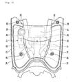
- is a side view of a scooter type motorcycle including a reservoir tank according to the invention;
- Fig. 2
- is a plan view showing a footrest in enlargement;
- Fig. 3
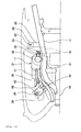
- is a side view showing a principal part in enlargement;
- Fig. 4
- is a plan view showing the principal part in enlargement;
- Fig. 5
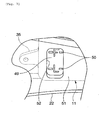
- is a sectional view along line V-V in
Fig. 3 ; - Fig. 6
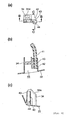
- is a diagram showing a pipe holder of an under cover; and
- Fig. 7
- is a side view showing an opening for visual recognition of storage capacity.
- In these figures, reference numeral 1 denotes the scooter type motorcycle (hereinafter simply referred to as scooter) according to this embodiment. This scooter 1 has a
footrest 4 provided between afront wheel 2 and arear wheel 3 so as to form a low floor and drives therear wheel 3 with a unit swingtype power unit 5 to run. - The
power unit 5 includes a water-cooled four-cyclesingle cylinder engine 6 and is supported on abody frame 7 to be described later so as to freely swing in the vertical direction. Thisengine 6 is constituted such that an axis of acylinder 8 is oriented in the longitudinal direction of the body. Although not shown in the figures, a fan is provided at an end on a body right side of a crank shaft, and a V belt continuously variable transmission for rear wheel drive is provided at an end on a body left side. A radiator 9 (seeFig. 3 ) is provided beside the fan, that is, at the end on the body right side of thisengine 6. This radiator 9 has a structure in which cooling water flows from anupper tank 9a to a lower tank 9 and is connected to a cooling water passage of theengine 6 by a not-shown cooling water hose. Areservoir tank 11 is connected to theupper tank 9a of this radiator 9 via areservoir pipe 10. - In
Fig. 1 ,reference numeral 12 denotes a front fork; 13, a steering handlebar; and 14, a seat. - The
body frame 7 includes ahead pipe 15 that supports thefront fork 12 so as to be steered freely, one downtube 16 that extends from thishead pipe 15 to thefootrest 4, and a pair of left and right rear frames 17 (seeFigs. 2 and4 ) that are connected to a rear end of this downtube 16. The rear end of thedown tube 16 is extended to a part below thefootrest 4 to be described later. As shown inFig. 3 , front ends of therear frames 17 are formed so as to extend in the longitudinal direction of a body inner side thefootrest 4 and bend in the vicinity of the rear end of thefootrest 4 to incline upward to the rear. - As shown in
Figs. 1 and5 , thefootrest 4 includes afoot board 21 for holding feet of a rider, an undercover 22 that covers thisfoot board 12 from the bottom thereof, and aside moll 23 that covers both sides of both the members from lateral directions. In the inside of thisfootrest 4, a space for housing the rear end of thedown tube 16, the front ends of therear frames 17, thereservoir tank 11 to be described later, and the like is formed. - As shown in
Figs. 2 and4 , thefoot board 21 and the undercover 22 are attached tobrackets rear frames 17, by bolts forattachment 26. To describe this more in detail, thefoot board 21 is attached to thebrackets attachment 26 in a state in which thefoot board 21 is placed on thebrackets Fig. 3 , in theunder cover 22, a stay forattachment 28 is integrally formed so as to extend upward from abottom wall 27. A flat portion of an upper end of this stay forattachment 28 is attached to thebrackets attachment 26 together with thefoot board 21 in a state in which the flat portion is sandwiched between thebrackets footboard 21. - As shown in
Fig. 2 , in thefoot board 21 according to this embodiment, a battery box 32 (seeFig. 5 ) housing abattery 31 is integrally formed at a rear end thereof. Thisbattery box 32 is formed in a box shape opening upward, and an opening at an upper end thereof is closed by a lid denoted byreference numeral 33 inFig. 2 . Thislid 33 is detachably attached to thefoot board 21. A cover referred to in the invention is constituted by thislid 33. - As shown in
Figs. 3 to 5 , thereservoir tank 11 is disposed in the inside of thefootrest 4 and at the end on the body right side, and an end on a body front side and an end on a body rear side are attached to the undercover 22. As shown inFig. 5 , a part where thereservoir tank 11 is attached to the undercover 22 adopts a structure in which a projectingpiece 35, which is protrudingly provided in thereservoir tank 11 so as to extend in the longitudinal direction of the body, is placed over a supportingpiece 34, which is protrudingly provided on thebottom wall 27 of the undercover 22 so as to extend upward, and is attached by the bolts forattachment 36. - In this embodiment, a bearing surface for
attachment 34a formed at the upper end of the supportingpiece 34 and the projectingpiece 35 are formed so as to incline downward to the right in a state in which the bearing surface forattachment 34a and the projectingpiece 35 are viewed from the front of the body. Thebearing surface 34a and the projectingpiece 35 are inclined in this way because molds with simple structures, which are released in the vertical direction, respectively, are used as an injection mold (not show) for molding the undercover 22 and a blow mold (not shown) for molding thereservoir tank 11. - As shown in
Fig. 5 , a water storage portion of thereservoir tank 11 is formed to take on an L shape in section and is formed such that the lower end thereof extends to the inside of the body below the rear frames 17 on the right side of the body. In other words, in thisreservoir tank 11, a dead space formed between therear frames 17 and the undercover 22 is used effectively to realize an increase in a volume. - A pipe for
water supply 37 is integrally formed at an upper end on the body rear side of thisreservoir tank 11 so as to project upward. In this pipe forwater supply 37, acap 38 is detachably attached to awater supply port 37a at an upper end thereof. As shown inFigs. 4 and5 , the pipe forwater supply 37 and thecap 38 are led to the outside of thefootrest 4 through a through hole 39a of atray 39 formed in thefoot board 21. Thetray 39 is formed so as to be adjacent to the body right side of thebattery box 32 and is opened and closed by thelid 33 together with thebattery box 32. - In other words, the water supply portion (the pipe for
water supply 37 and the cap 38) of thereservoir tank 11 is covered from the top thereof by thelid 33 so as not to appear on the exterior of the body usually. In thetray 39 according to this embodiment, apartition wall 40 is vertically provided between thetray 39 an thebattery box 32 such that, even if cooling water spills when the cooling water is supplied to thereservoir tank 11, the cooling water never flows into thebattery box 32. - As shown in
Figs. 3 and4 , abreather pipe 41 is connected to the upper end of thereservoir tank 11 and the vicinity of the front of the pipe forwater supply 37. The other end of thereservoir pipe 10, one end of which is connected to the radiator 9, is connected to the lower end of thereservoir tank 11 and the end on the body rear side. - As shown in
Figs. 3 ,4 , and6 , the other end of thebreather pipe 41 is held by being inserted into apipe holder 42 of theunder cover 22. Thispipe holder 42 is formed integrally with abottom wall 28 of theunder cover 22 and is disposed further in the front of the body than thereservoir tank 11. - As shown in
Fig. 6 , thispipe holder 42 includes apipe section 43 that is formed so as to extend upward integrally with the supportingpiece 34 and astopper 44 that is formed at a lower end of thispipe section 43 so as to project into the pipe. Thepipe section 43 is formed so as to take on a C shape in section and is constituted to hold thebreather pipe 41 in an elastically deformed state such that an outer diameter of thebreather pipe 41 is slightly reduced. - The
stopper 44 is a portion for regulating an amount of insertion such that thebreather pipe 41 is never projected to a part lower than thepipe holder 42 and is formed such that a tip of the breather pipe inserted into thepipe section 43 comes into abutment against thestopper 44. A position of the tip of thebreather pipe 41 is regulated by thisstopper 44, whereby it becomes unnecessary to measure an amount of insertion of thebreather pipe 41 when thebreather pipe 41 is assembled, and workability of mounting work is improved. At the same time, since thebreather pipe 41 never projects to a part below theunder cover 22, the exterior of the scooter 1 is never spoiled. - As shown in
Fig. 6(b) , a lower end of thebreather pipe 41 according to this embodiment opens to the inside of aspace 45 that is formed so as to open downward in theunder cover 22. The lower end of thebreather pipe 41 is positioned in thisspace 45, whereby it becomes less likely that an opening at the lower end of thebreather pipe 41 is clogged up by mud. - As shown in
Fig. 5 , a recessedgroove 48 holding amain harness 47 is formed on aninner wall 46 on the body inner side of thereservoir tank 11. As shown inFigs. 3 and7 , alevel gauge 50 is formed on anouter wall 49 on the body outer side. The recessedgroove 48 is formed so as to take on a semicircular shape in section such that themain harness 47 can fit in the recessedgroove 48. Themain harness 47 is held in thereservoir tank 11 in this way, whereby the number of clamps and holders for holding the main harness can be reduced. Thus, the number of components and the number of work steps are reduced, and reduction in cost can be realized. - The
level gauge 50 indicates a position of a water surface in a state in which a reserved amount of cooling water in thereservoir tank 11 has reached an amount of an allowable minimum limit and a position of a water surface in a state in which a reserved amount of the cooling water has reached an amount of an allowable maximum limit. Thelevel gauge 50 is formed at the time of molding using the mold for molding thereservoir tank 11. As shown inFig. 7 , anopening 52 for visual recognition of storage capacity is formed in asidewall 51 of theunder cover 22 opposed to thelevel gauge 50. Thereservoir tank 11 according to this embodiment is formed of a synthetic resin material through which the water surface of the cooling water can be seen. Thelevel gauge 50 and the water surface can be compared through theopening 52. - In the scooter 1 constituted as described above, in order to mount the
reservoir tank 11 on the body, thereservoir tank 11 is mounted in a state in which thereservoir tank 11 is assembled to theunder cover 22 in advance. In other words, thereservoir tank 11 is assembled to theunder cover 22 in advance, and this undercover 22 is attached to thebrackets body frame 7, whereby thereservoir tank 11 can be attached to thebody frame 7. - Therefore, in performing attachment work for this
reservoir tank 11, a worker can easily perform the attachment work holding the relatively large undercover 22. - In addition, in the scooter 1 according to this embodiment, the
reservoir tank 11 and the bolts forattachment 26 are covered by the undercover 2 and thefoot board 21, and the water supply portion (the pipe forwater supply 37 and the cap 38) is covered by thelid 33. Consequently, in this scooter 1, thereservoir tank 11 can be prevented from appearing on the exterior of the body by thefootrest 4, which is always provided in this type of a vehicle, and thelid 33 covering the water supply portion. In preventing the bolts forattachment 26 from being exposed to the outside of the body, since a separate small cover is unnecessary other than theunder cover 22, reduction in cost can be realized compared with the case in which this small cover is used. - The projecting piece for
attachment 35 is provided protrudingly in the longitudinal direction of the body, and thereservoir tank 11 according to this embodiment is attached to the supportingpieces 34, which is formed on the bottom wall of theunder cover 22 so as to project upward, via the projectingpiece 35. Thus, the projectingpiece 34 and the supportingpiece 35 are positioned at substantially the same height as thereservoir tank 11. Consequently, it is possible to house thereservoir tank 11 in the inside of thefootrest 4 while forming thefootrest 4 to be compact in the vertical direction. - In this embodiment, the projecting
piece 35 and the bearing surface forattachment 34a incline in the lateral direction of the body. Thus, it is possible to mold thereservoir tank 11 and theunder cover 22 with molds, a release direction of which is the vertical direction, respectively. Consequently, it is possible to form both thereservoir tank 11 and theunder cover 22 with molds with simple structures compared with the case in which a slide core or the like is used for the molds. - In the
under cover 22 according to this embodiment, the opening for visual recognition ofstorage capacity 52 is formed on thesidewall 51 opposed to thereservoir tank 11. Thus, it is possible to position the level gauge 50 (visually recognized portion) of thereservoir tank 11 with respect to the opening for visual recognition ofstorage capacity 52 with high accuracy. This is because the opening for visual recognition ofstorage capacity 52 is formed in theunder cover 22 to which thereservoir tank 11 is attached, and positions of theopening 52 and an attaching part of thereservoir tank 11 are determined accurately by a mold. - As described before, the present invention has been devised in order to facilitate attachment work for a reservoir tank using a body cover and preventing the reservoir tank and an attachment part thereof from being exposed to the outside of a body while realizing reduction in cost.
- Therefore, a scooter type motorcycle is provided, preferably a scooter type motorcycle that has a low-floor footrest having a foot board and an under cover provided between a front wheel and a rear wheel and is mounted with a water-cooled engine, wherein a reservoir tank is housed in the inside of the footrest, and further preferably this reservoir tank is attached to the under cover in a state in which a water supply portion is covered by a cover that is provided in the foot board so as to be openable and closable.
- Therein, a preferably projecting piece for attachment is provided protrudingly in a longitudinal direction of the body and is attached to a supporting piece, which is formed on a bottom wall of the under cover so as to project upward, via the projecting piece.
- More preferably, the projecting piece and a bearing surface for attachment of the supporting piece are inclined in a lateral direction of the body.
- According to the invention, work for attaching the reservoir tank to a body frame is finished by attaching the under cover to the body frame in a state in which the reservoir tank is attached to the under cover in advance. Therefore, in performing this attachment work, since a component held by a worker is a relatively large under cover, the attachment work can be performed easily compared with the case in which the reservoir tank is directly attached to a bracket of the body frame.
- In this scooter type motorcycle, the reservoir tank can be prevented from appearing on an exterior of the body by the footrest, which is always provided in this type of a vehicle, and the cover covering the water supply portion. Thereby, in preventing bolts for attaching the reservoir tank to the under cover from being exposed to the outside of the body, a small cover separate from the under cover is not required, and therefore the number of components and the number of assembly steps are decreased and reduction in cost can be realized.
- Therefore, the attachment work for the reservoir tank can be facilitated using the under cover equivalent to the body cover, and the reservoir tank and the attachment part thereof can be prevented from being exposed to the outside of the body while realizing reduction in cost.
- Further, since the projecting piece for attaching the reservoir tank to the under cover and the supporting piece are positioned at substantially the same height, the reservoir tank can be housed in the inside of the footrest while forming the footrest to be compact in the vertical direction.
- Moreover, the reservoir tank and the under cover can be formed by a mold, a release direction of which is the vertical direction, respectively. Consequently, since a structure of the mold is simplified compared with the case in which a slide core or the like is used, manufacturing cost for the mold can be reduced.
- Further, since the opening for visual recognition of storage capacity is formed in the under cover to which the reservoir tank is attached, a visually recognized portion of the reservoir tank can be positioned at high accuracy with respect to the opening for visual recognition of storage capacity. Consequently, the visually recognized portion of the reservoir tank can be visually recognized accurately.
- As explained above, for facilitating attachment work for a reservoir tank using a body cover and prevent the reservoir tank and an attaching part of the reservoir tank from being exposed to the outside of a body while realizing reduction in cost, a
reservoir tank 11 is housed in the inside of afootrest 4 having afoot board 21 and an undercover 22. In thereservoir tank 11, a pipe forwater supply 37 and acap 38 are covered by alid 33 provided in thefoot board 21 so as to be openable and closable. Thisreservoir tank 11 is attached to theunder cover 22.
Claims (12)
- Scooter type motorcycle comprising a water-cooled engine (6), a low-floor footrest (4) having a foot board (21) and an under cover (22) provided between a front wheel (2) and a rear wheel (3), and
a reservoir tank (11) for storing a cooling liquid housed within the footrest (4), wherein a water supply portion (37) of the reservoir tank (11) is covered to the outside of the motorcycle (1) by a detachable cover (33) which forms part of the foot board (21), characterized in that the reservoir tank (11) is attached to the under cover (22), and an attachment means (36) is provided for attachment of the reservoir tank (11) to the under cover (22), wherein the attachment means (36) is mounted from an inner side of the under cover (22) in a direction towards an outer side of the under cover (22). - Scooter type motorcycle according to claim 1, characterized in that the detachable cover (33) covers a battery box (32) to the outside.
- Scooter type motorcycle according to claim 1 or 2, characterized in that a projecting piece (35) for attachment of the reservoir tank (11) to the motorcycle (1) is provided thereon and protrudingly in a longitudinal direction of a motorcycle body, the projecting piece (35) being attached to a supporting piece (34), which is formed on a bottom wall (27) of the under cover (22) so as to project upward.
- Scooter type motorcycle according to claim 3, characterized in that the projecting piece (35) and a bearing surface for attachment of the supporting piece (34) are inclined in a lateral direction of the motorcycle and/or tank body.
- Scooter type motorcycle according to at least one of the claims 1 to 4, characterized in that an end portion of the attachment means (36), to which an attachment tool is applicable, is directed to an inner side of the under cover (22).
- Scooter type motorcycle according to claim 5, characterized in that said attachment means (36) is a bolt.
- Scooter type motorcycle according to at least one of the claims 1 to 6, characterized in that an opening (52) for visual recognition of storage capacity of the reservoir tank (11) is formed on a sidewall (51) opposed to the reservoir tank (11) in the under cover (22).
- Scooter type motorcycle according to at least one of the claims 1 to 7, characterized in that a level gauge (50) indicating a position of an upper surface of a cooling liquid within the reservoir tank (11) is provided at an outer wall (49) of the reservoir tank (11) so as to be visible through an opening (52) formed in a sidewall (51) of an under cover (22) of the motorcycle (1).
- Scooter type motorcycle according to at least one of the claims 1 to 8, characterized in that a water storage portion of the reservoir tank (11) is formed in an L-shape if seen in a cross-sectional view of the motorcycle (1).
- Scooter type motorcycle according to at least one of the claims 1 to 9, characterized in that a lower end of the reservoir tank (11) extends below rear frames (17) of a body of the motorcycle (1), being positioned in a dead space formed between the rear frames (17) and the under cover (22).
- Scooter type motorcycle according to at least one of the claims 1 to 10, characterized in that a water supply pipe (37) is integrally formed at an upper end of the reservoir tank (11), the water supply pipe (37) comprising a water supply part (37a) which is closable by a detachable cap (38).
- Scooter type motorcycle according to at least one of the claims 1 to 11, characterized in that a recessed groove (48) for holding a main harness (47) is formed on an inner side wall (46) of the reservoir tank (11).
Applications Claiming Priority (2)
| Application Number | Priority Date | Filing Date | Title |
|---|---|---|---|
| JP2003359488A JP4351021B2 (en) | 2003-10-20 | 2003-10-20 | Scooter type motorcycle |
| JP2003359488 | 2003-10-20 |
Publications (3)
| Publication Number | Publication Date |
|---|---|
| EP1526064A2 EP1526064A2 (en) | 2005-04-27 |
| EP1526064A3 EP1526064A3 (en) | 2007-06-20 |
| EP1526064B1 true EP1526064B1 (en) | 2013-06-19 |
Family
ID=34386460
Family Applications (1)
| Application Number | Title | Priority Date | Filing Date |
|---|---|---|---|
| EP04024953.4A Not-in-force EP1526064B1 (en) | 2003-10-20 | 2004-10-20 | Scooter type motorcycle |
Country Status (5)
| Country | Link |
|---|---|
| EP (1) | EP1526064B1 (en) |
| JP (1) | JP4351021B2 (en) |
| CN (1) | CN1329238C (en) |
| ES (1) | ES2416134T3 (en) |
| TW (1) | TWI268244B (en) |
Families Citing this family (4)
| Publication number | Priority date | Publication date | Assignee | Title |
|---|---|---|---|---|
| JP5283994B2 (en) * | 2008-07-16 | 2013-09-04 | 川崎重工業株式会社 | Reservoir tank support structure |
| CN109606523B (en) * | 2013-03-28 | 2021-07-02 | 哈特移动有限责任公司 | Small-sized motorcycle |
| CN105416459A (en) * | 2014-09-16 | 2016-03-23 | 光阳工业股份有限公司 | Water-cooling system arrangement structure of motorcycle |
| JP6209792B2 (en) * | 2016-03-31 | 2017-10-11 | 本田技研工業株式会社 | Reservoir tank mounting part structure for saddle-ride type vehicles |
Family Cites Families (12)
| Publication number | Priority date | Publication date | Assignee | Title |
|---|---|---|---|---|
| JPS5213252B2 (en) * | 1973-06-06 | 1977-04-13 | ||
| DE3617073A1 (en) * | 1986-05-21 | 1987-11-26 | Robere Oehl | Moped and motorcycle tank lid with an integrated level indicator via a viewing window with a green marking ball operated by a plastic hose with a float |
| US4807472A (en) * | 1987-07-31 | 1989-02-28 | Harley-Davidson, Inc. | Motorcycle fuel level gauge |
| JP3120529B2 (en) | 1992-01-31 | 2000-12-25 | スズキ株式会社 | Motorcycle cooling water reservoir tank mounting structure |
| ES2131364T3 (en) * | 1995-06-29 | 1999-07-16 | Yamaha Motor Co Ltd | MOTORCYCLE OF THE "SCOOTER" TYPE. |
| JP4145370B2 (en) * | 1996-06-27 | 2008-09-03 | 本田技研工業株式会社 | Engine cooling structure for scooter type vehicles |
| CN2294336Y (en) * | 1996-09-05 | 1998-10-14 | 国营河南柴油机厂 | Water cooling engine for motor cycle |
| JP4149551B2 (en) * | 1998-02-18 | 2008-09-10 | 本田技研工業株式会社 | Oil tank installation structure for scooter type vehicles |
| JP4270351B2 (en) * | 1998-04-23 | 2009-05-27 | ヤマハ発動機株式会社 | Storage box for scooter type vehicles |
| JP4303361B2 (en) * | 1999-06-07 | 2009-07-29 | 本田技研工業株式会社 | Scooter type vehicle |
| US6588529B2 (en) * | 2000-07-05 | 2003-07-08 | Yamaha Hatsudoki Kabishuki Kaisha | Body cover and structure for motorcycle |
| JP2003019992A (en) * | 2001-07-09 | 2003-01-21 | Yamaha Motor Co Ltd | Cooling system of scooter type motorcycle |
-
2003
- 2003-10-20 JP JP2003359488A patent/JP4351021B2/en not_active Expired - Fee Related
-
2004
- 2004-10-14 TW TW093131223A patent/TWI268244B/en not_active IP Right Cessation
- 2004-10-20 EP EP04024953.4A patent/EP1526064B1/en not_active Not-in-force
- 2004-10-20 ES ES04024953T patent/ES2416134T3/en active Active
- 2004-10-20 CN CNB2004100864679A patent/CN1329238C/en not_active Expired - Fee Related
Also Published As
| Publication number | Publication date |
|---|---|
| ES2416134T3 (en) | 2013-07-30 |
| TWI268244B (en) | 2006-12-11 |
| TW200528324A (en) | 2005-09-01 |
| EP1526064A2 (en) | 2005-04-27 |
| JP4351021B2 (en) | 2009-10-28 |
| EP1526064A3 (en) | 2007-06-20 |
| JP2005119606A (en) | 2005-05-12 |
| CN1329238C (en) | 2007-08-01 |
| CN1608934A (en) | 2005-04-27 |
Similar Documents
| Publication | Publication Date | Title |
|---|---|---|
| EP1561941B1 (en) | A fuel injection system for a saddle ride type four-wheel vehicle | |
| US6644693B2 (en) | Scooter type vehicle | |
| US7845446B2 (en) | Scooter type vehicle | |
| JP5926653B2 (en) | Storage structure of saddle-ride type vehicle | |
| EP2176115B1 (en) | Scooter type vehicle | |
| BR102014030169B1 (en) | VEHICLE WITH SADDLE | |
| JP5629245B2 (en) | Vehicle with step floor | |
| JP2007203816A (en) | Reserve tank structure | |
| US8960753B2 (en) | Storage structure of saddle riding type vehicle | |
| CN101301914B (en) | Fuel supply structure for small-type vehicle | |
| JP2007076556A (en) | Vehicular equipment accommodation structure | |
| JP3974405B2 (en) | Scooter type vehicle | |
| EP1526064B1 (en) | Scooter type motorcycle | |
| US6581709B2 (en) | Small article compartment device for saddle type vehicle | |
| WO2014158102A1 (en) | Canister mounting structure for a motorcycle | |
| CN110949575B (en) | Saddle-ride type vehicle | |
| EP2769902B1 (en) | Accessory socket layout structure of saddle-ride type vehicle | |
| JP2002220076A (en) | Cooler for vehicle traveling on unleveled ground | |
| JP4811959B2 (en) | Scooter type motorcycle | |
| JP2009051490A (en) | Cover, hose fixing structure and straddle-type vehicle | |
| EP2213560B1 (en) | A motorcycle wherein at least two liquid tanks are located, reciprocally disposed and shaped according to an improved layout | |
| EP1990264B1 (en) | Fuel supply structure for small-type vehicle | |
| JP2005119607A (en) | Scooter type motorcycle | |
| JP2017007646A (en) | Motorcycle | |
| JP6384192B2 (en) | Rear lamp mounting structure for saddle riding type vehicles |
Legal Events
| Date | Code | Title | Description |
|---|---|---|---|
| PUAI | Public reference made under article 153(3) epc to a published international application that has entered the european phase |
Free format text: ORIGINAL CODE: 0009012 |
|
| AK | Designated contracting states |
Kind code of ref document: A2 Designated state(s): AT BE BG CH CY CZ DE DK EE ES FI FR GB GR HU IE IT LI LU MC NL PL PT RO SE SI SK TR |
|
| AX | Request for extension of the european patent |
Extension state: AL HR LT LV MK |
|
| PUAL | Search report despatched |
Free format text: ORIGINAL CODE: 0009013 |
|
| AK | Designated contracting states |
Kind code of ref document: A3 Designated state(s): AT BE BG CH CY CZ DE DK EE ES FI FR GB GR HU IE IT LI LU MC NL PL PT RO SE SI SK TR |
|
| AX | Request for extension of the european patent |
Extension state: AL HR LT LV MK |
|
| 17P | Request for examination filed |
Effective date: 20070608 |
|
| AKX | Designation fees paid |
Designated state(s): AT BE BG CH CY CZ DE DK EE ES FI FR GB GR HU IE IT LI LU MC NL PL PT RO SE SI SK TR |
|
| 17Q | First examination report despatched |
Effective date: 20100630 |
|
| REG | Reference to a national code |
Ref country code: DE Ref legal event code: R079 Ref document number: 602004042447 Country of ref document: DE Free format text: PREVIOUS MAIN CLASS: B62J0035000000 Ipc: B62J0025000000 |
|
| RIC1 | Information provided on ipc code assigned before grant |
Ipc: B62J 25/00 20060101AFI20121211BHEP Ipc: B62J 17/00 20060101ALI20121211BHEP Ipc: B62J 37/00 20060101ALI20121211BHEP Ipc: B62K 11/00 20130101ALI20121211BHEP |
|
| GRAP | Despatch of communication of intention to grant a patent |
Free format text: ORIGINAL CODE: EPIDOSNIGR1 |
|
| RIN1 | Information on inventor provided before grant (corrected) |
Inventor name: KOIKE, MUNETAKA |
|
| GRAS | Grant fee paid |
Free format text: ORIGINAL CODE: EPIDOSNIGR3 |
|
| GRAA | (expected) grant |
Free format text: ORIGINAL CODE: 0009210 |
|
| AK | Designated contracting states |
Kind code of ref document: B1 Designated state(s): AT BE BG CH CY CZ DE DK EE ES FI FR GB GR HU IE IT LI LU MC NL PL PT RO SE SI SK TR |
|
| REG | Reference to a national code |
Ref country code: GB Ref legal event code: FG4D |
|
| REG | Reference to a national code |
Ref country code: CH Ref legal event code: EP |
|
| REG | Reference to a national code |
Ref country code: AT Ref legal event code: REF Ref document number: 617485 Country of ref document: AT Kind code of ref document: T Effective date: 20130715 |
|
| REG | Reference to a national code |
Ref country code: ES Ref legal event code: FG2A Ref document number: 2416134 Country of ref document: ES Kind code of ref document: T3 Effective date: 20130730 |
|
| REG | Reference to a national code |
Ref country code: IE Ref legal event code: FG4D |
|
| REG | Reference to a national code |
Ref country code: DE Ref legal event code: R096 Ref document number: 602004042447 Country of ref document: DE Effective date: 20130814 |
|
| PG25 | Lapsed in a contracting state [announced via postgrant information from national office to epo] |
Ref country code: SI Free format text: LAPSE BECAUSE OF FAILURE TO SUBMIT A TRANSLATION OF THE DESCRIPTION OR TO PAY THE FEE WITHIN THE PRESCRIBED TIME-LIMIT Effective date: 20130619 Ref country code: GR Free format text: LAPSE BECAUSE OF FAILURE TO SUBMIT A TRANSLATION OF THE DESCRIPTION OR TO PAY THE FEE WITHIN THE PRESCRIBED TIME-LIMIT Effective date: 20130920 Ref country code: FI Free format text: LAPSE BECAUSE OF FAILURE TO SUBMIT A TRANSLATION OF THE DESCRIPTION OR TO PAY THE FEE WITHIN THE PRESCRIBED TIME-LIMIT Effective date: 20130619 Ref country code: SE Free format text: LAPSE BECAUSE OF FAILURE TO SUBMIT A TRANSLATION OF THE DESCRIPTION OR TO PAY THE FEE WITHIN THE PRESCRIBED TIME-LIMIT Effective date: 20130619 |
|
| REG | Reference to a national code |
Ref country code: AT Ref legal event code: MK05 Ref document number: 617485 Country of ref document: AT Kind code of ref document: T Effective date: 20130619 |
|
| PG25 | Lapsed in a contracting state [announced via postgrant information from national office to epo] |
Ref country code: BG Free format text: LAPSE BECAUSE OF FAILURE TO SUBMIT A TRANSLATION OF THE DESCRIPTION OR TO PAY THE FEE WITHIN THE PRESCRIBED TIME-LIMIT Effective date: 20130919 |
|
| REG | Reference to a national code |
Ref country code: NL Ref legal event code: VDEP Effective date: 20130619 |
|
| PG25 | Lapsed in a contracting state [announced via postgrant information from national office to epo] |
Ref country code: CY Free format text: LAPSE BECAUSE OF FAILURE TO SUBMIT A TRANSLATION OF THE DESCRIPTION OR TO PAY THE FEE WITHIN THE PRESCRIBED TIME-LIMIT Effective date: 20130703 Ref country code: AT Free format text: LAPSE BECAUSE OF FAILURE TO SUBMIT A TRANSLATION OF THE DESCRIPTION OR TO PAY THE FEE WITHIN THE PRESCRIBED TIME-LIMIT Effective date: 20130619 Ref country code: CZ Free format text: LAPSE BECAUSE OF FAILURE TO SUBMIT A TRANSLATION OF THE DESCRIPTION OR TO PAY THE FEE WITHIN THE PRESCRIBED TIME-LIMIT Effective date: 20130619 Ref country code: EE Free format text: LAPSE BECAUSE OF FAILURE TO SUBMIT A TRANSLATION OF THE DESCRIPTION OR TO PAY THE FEE WITHIN THE PRESCRIBED TIME-LIMIT Effective date: 20130619 Ref country code: PT Free format text: LAPSE BECAUSE OF FAILURE TO SUBMIT A TRANSLATION OF THE DESCRIPTION OR TO PAY THE FEE WITHIN THE PRESCRIBED TIME-LIMIT Effective date: 20131021 Ref country code: SK Free format text: LAPSE BECAUSE OF FAILURE TO SUBMIT A TRANSLATION OF THE DESCRIPTION OR TO PAY THE FEE WITHIN THE PRESCRIBED TIME-LIMIT Effective date: 20130619 Ref country code: BE Free format text: LAPSE BECAUSE OF FAILURE TO SUBMIT A TRANSLATION OF THE DESCRIPTION OR TO PAY THE FEE WITHIN THE PRESCRIBED TIME-LIMIT Effective date: 20130619 |
|
| PG25 | Lapsed in a contracting state [announced via postgrant information from national office to epo] |
Ref country code: RO Free format text: LAPSE BECAUSE OF FAILURE TO SUBMIT A TRANSLATION OF THE DESCRIPTION OR TO PAY THE FEE WITHIN THE PRESCRIBED TIME-LIMIT Effective date: 20130619 Ref country code: NL Free format text: LAPSE BECAUSE OF FAILURE TO SUBMIT A TRANSLATION OF THE DESCRIPTION OR TO PAY THE FEE WITHIN THE PRESCRIBED TIME-LIMIT Effective date: 20130619 Ref country code: PL Free format text: LAPSE BECAUSE OF FAILURE TO SUBMIT A TRANSLATION OF THE DESCRIPTION OR TO PAY THE FEE WITHIN THE PRESCRIBED TIME-LIMIT Effective date: 20130619 |
|
| PG25 | Lapsed in a contracting state [announced via postgrant information from national office to epo] |
Ref country code: CY Free format text: LAPSE BECAUSE OF FAILURE TO SUBMIT A TRANSLATION OF THE DESCRIPTION OR TO PAY THE FEE WITHIN THE PRESCRIBED TIME-LIMIT Effective date: 20130619 |
|
| PLBE | No opposition filed within time limit |
Free format text: ORIGINAL CODE: 0009261 |
|
| STAA | Information on the status of an ep patent application or granted ep patent |
Free format text: STATUS: NO OPPOSITION FILED WITHIN TIME LIMIT |
|
| PG25 | Lapsed in a contracting state [announced via postgrant information from national office to epo] |
Ref country code: DK Free format text: LAPSE BECAUSE OF FAILURE TO SUBMIT A TRANSLATION OF THE DESCRIPTION OR TO PAY THE FEE WITHIN THE PRESCRIBED TIME-LIMIT Effective date: 20130619 |
|
| REG | Reference to a national code |
Ref country code: DE Ref legal event code: R119 Ref document number: 602004042447 Country of ref document: DE |
|
| 26N | No opposition filed |
Effective date: 20140320 |
|
| PG25 | Lapsed in a contracting state [announced via postgrant information from national office to epo] |
Ref country code: MC Free format text: LAPSE BECAUSE OF FAILURE TO SUBMIT A TRANSLATION OF THE DESCRIPTION OR TO PAY THE FEE WITHIN THE PRESCRIBED TIME-LIMIT Effective date: 20130619 |
|
| REG | Reference to a national code |
Ref country code: CH Ref legal event code: PL |
|
| GBPC | Gb: european patent ceased through non-payment of renewal fee |
Effective date: 20131020 |
|
| REG | Reference to a national code |
Ref country code: DE Ref legal event code: R097 Ref document number: 602004042447 Country of ref document: DE Effective date: 20140320 |
|
| REG | Reference to a national code |
Ref country code: IE Ref legal event code: MM4A |
|
| PG25 | Lapsed in a contracting state [announced via postgrant information from national office to epo] |
Ref country code: LI Free format text: LAPSE BECAUSE OF NON-PAYMENT OF DUE FEES Effective date: 20131031 Ref country code: GB Free format text: LAPSE BECAUSE OF NON-PAYMENT OF DUE FEES Effective date: 20131020 Ref country code: CH Free format text: LAPSE BECAUSE OF NON-PAYMENT OF DUE FEES Effective date: 20131031 |
|
| REG | Reference to a national code |
Ref country code: DE Ref legal event code: R119 Ref document number: 602004042447 Country of ref document: DE Effective date: 20140501 |
|
| PG25 | Lapsed in a contracting state [announced via postgrant information from national office to epo] |
Ref country code: DE Free format text: LAPSE BECAUSE OF NON-PAYMENT OF DUE FEES Effective date: 20140501 |
|
| PG25 | Lapsed in a contracting state [announced via postgrant information from national office to epo] |
Ref country code: IE Free format text: LAPSE BECAUSE OF NON-PAYMENT OF DUE FEES Effective date: 20131020 |
|
| PG25 | Lapsed in a contracting state [announced via postgrant information from national office to epo] |
Ref country code: TR Free format text: LAPSE BECAUSE OF FAILURE TO SUBMIT A TRANSLATION OF THE DESCRIPTION OR TO PAY THE FEE WITHIN THE PRESCRIBED TIME-LIMIT Effective date: 20130619 |
|
| PG25 | Lapsed in a contracting state [announced via postgrant information from national office to epo] |
Ref country code: LU Free format text: LAPSE BECAUSE OF NON-PAYMENT OF DUE FEES Effective date: 20131020 Ref country code: HU Free format text: LAPSE BECAUSE OF FAILURE TO SUBMIT A TRANSLATION OF THE DESCRIPTION OR TO PAY THE FEE WITHIN THE PRESCRIBED TIME-LIMIT; INVALID AB INITIO Effective date: 20041020 |
|
| REG | Reference to a national code |
Ref country code: FR Ref legal event code: PLFP Year of fee payment: 12 |
|
| PGFP | Annual fee paid to national office [announced via postgrant information from national office to epo] |
Ref country code: IT Payment date: 20151028 Year of fee payment: 12 |
|
| PGFP | Annual fee paid to national office [announced via postgrant information from national office to epo] |
Ref country code: FR Payment date: 20151023 Year of fee payment: 12 Ref country code: ES Payment date: 20151028 Year of fee payment: 12 |
|
| REG | Reference to a national code |
Ref country code: FR Ref legal event code: ST Effective date: 20170630 |
|
| PG25 | Lapsed in a contracting state [announced via postgrant information from national office to epo] |
Ref country code: FR Free format text: LAPSE BECAUSE OF NON-PAYMENT OF DUE FEES Effective date: 20161102 |
|
| PG25 | Lapsed in a contracting state [announced via postgrant information from national office to epo] |
Ref country code: IT Free format text: LAPSE BECAUSE OF NON-PAYMENT OF DUE FEES Effective date: 20161020 |
|
| PG25 | Lapsed in a contracting state [announced via postgrant information from national office to epo] |
Ref country code: ES Free format text: LAPSE BECAUSE OF NON-PAYMENT OF DUE FEES Effective date: 20161021 |
|
| REG | Reference to a national code |
Ref country code: ES Ref legal event code: FD2A Effective date: 20181123 |