EP1525862A2 - Tibiaplateaukomponente für eine Knieendoprothese. - Google Patents
Tibiaplateaukomponente für eine Knieendoprothese. Download PDFInfo
- Publication number
- EP1525862A2 EP1525862A2 EP04024984A EP04024984A EP1525862A2 EP 1525862 A2 EP1525862 A2 EP 1525862A2 EP 04024984 A EP04024984 A EP 04024984A EP 04024984 A EP04024984 A EP 04024984A EP 1525862 A2 EP1525862 A2 EP 1525862A2
- Authority
- EP
- European Patent Office
- Prior art keywords
- component
- tibial
- coupling
- radius
- sliding
- Prior art date
- Legal status (The legal status is an assumption and is not a legal conclusion. Google has not performed a legal analysis and makes no representation as to the accuracy of the status listed.)
- Withdrawn
Links
Images


Classifications
-
- A—HUMAN NECESSITIES
- A61—MEDICAL OR VETERINARY SCIENCE; HYGIENE
- A61F—FILTERS IMPLANTABLE INTO BLOOD VESSELS; PROSTHESES; DEVICES PROVIDING PATENCY TO, OR PREVENTING COLLAPSING OF, TUBULAR STRUCTURES OF THE BODY, e.g. STENTS; ORTHOPAEDIC, NURSING OR CONTRACEPTIVE DEVICES; FOMENTATION; TREATMENT OR PROTECTION OF EYES OR EARS; BANDAGES, DRESSINGS OR ABSORBENT PADS; FIRST-AID KITS
- A61F2/00—Filters implantable into blood vessels; Prostheses, i.e. artificial substitutes or replacements for parts of the body; Appliances for connecting them with the body; Devices providing patency to, or preventing collapsing of, tubular structures of the body, e.g. stents
- A61F2/02—Prostheses implantable into the body
- A61F2/30—Joints
- A61F2/38—Joints for elbows or knees
- A61F2/389—Tibial components
-
- A—HUMAN NECESSITIES
- A61—MEDICAL OR VETERINARY SCIENCE; HYGIENE
- A61F—FILTERS IMPLANTABLE INTO BLOOD VESSELS; PROSTHESES; DEVICES PROVIDING PATENCY TO, OR PREVENTING COLLAPSING OF, TUBULAR STRUCTURES OF THE BODY, e.g. STENTS; ORTHOPAEDIC, NURSING OR CONTRACEPTIVE DEVICES; FOMENTATION; TREATMENT OR PROTECTION OF EYES OR EARS; BANDAGES, DRESSINGS OR ABSORBENT PADS; FIRST-AID KITS
- A61F2/00—Filters implantable into blood vessels; Prostheses, i.e. artificial substitutes or replacements for parts of the body; Appliances for connecting them with the body; Devices providing patency to, or preventing collapsing of, tubular structures of the body, e.g. stents
- A61F2/02—Prostheses implantable into the body
- A61F2/30—Joints
- A61F2/38—Joints for elbows or knees
- A61F2/3868—Joints for elbows or knees with sliding tibial bearing
-
- A—HUMAN NECESSITIES
- A61—MEDICAL OR VETERINARY SCIENCE; HYGIENE
- A61F—FILTERS IMPLANTABLE INTO BLOOD VESSELS; PROSTHESES; DEVICES PROVIDING PATENCY TO, OR PREVENTING COLLAPSING OF, TUBULAR STRUCTURES OF THE BODY, e.g. STENTS; ORTHOPAEDIC, NURSING OR CONTRACEPTIVE DEVICES; FOMENTATION; TREATMENT OR PROTECTION OF EYES OR EARS; BANDAGES, DRESSINGS OR ABSORBENT PADS; FIRST-AID KITS
- A61F2/00—Filters implantable into blood vessels; Prostheses, i.e. artificial substitutes or replacements for parts of the body; Appliances for connecting them with the body; Devices providing patency to, or preventing collapsing of, tubular structures of the body, e.g. stents
- A61F2/02—Prostheses implantable into the body
- A61F2/30—Joints
- A61F2/38—Joints for elbows or knees
- A61F2/3859—Femoral components
-
- A—HUMAN NECESSITIES
- A61—MEDICAL OR VETERINARY SCIENCE; HYGIENE
- A61F—FILTERS IMPLANTABLE INTO BLOOD VESSELS; PROSTHESES; DEVICES PROVIDING PATENCY TO, OR PREVENTING COLLAPSING OF, TUBULAR STRUCTURES OF THE BODY, e.g. STENTS; ORTHOPAEDIC, NURSING OR CONTRACEPTIVE DEVICES; FOMENTATION; TREATMENT OR PROTECTION OF EYES OR EARS; BANDAGES, DRESSINGS OR ABSORBENT PADS; FIRST-AID KITS
- A61F2/00—Filters implantable into blood vessels; Prostheses, i.e. artificial substitutes or replacements for parts of the body; Appliances for connecting them with the body; Devices providing patency to, or preventing collapsing of, tubular structures of the body, e.g. stents
- A61F2/02—Prostheses implantable into the body
- A61F2/30—Joints
- A61F2002/30001—Additional features of subject-matter classified in A61F2/28, A61F2/30 and subgroups thereof
- A61F2002/30108—Shapes
- A61F2002/3011—Cross-sections or two-dimensional shapes
- A61F2002/30112—Rounded shapes, e.g. with rounded corners
- A61F2002/30131—Rounded shapes, e.g. with rounded corners horseshoe- or crescent- or C-shaped or U-shaped
-
- A—HUMAN NECESSITIES
- A61—MEDICAL OR VETERINARY SCIENCE; HYGIENE
- A61F—FILTERS IMPLANTABLE INTO BLOOD VESSELS; PROSTHESES; DEVICES PROVIDING PATENCY TO, OR PREVENTING COLLAPSING OF, TUBULAR STRUCTURES OF THE BODY, e.g. STENTS; ORTHOPAEDIC, NURSING OR CONTRACEPTIVE DEVICES; FOMENTATION; TREATMENT OR PROTECTION OF EYES OR EARS; BANDAGES, DRESSINGS OR ABSORBENT PADS; FIRST-AID KITS
- A61F2/00—Filters implantable into blood vessels; Prostheses, i.e. artificial substitutes or replacements for parts of the body; Appliances for connecting them with the body; Devices providing patency to, or preventing collapsing of, tubular structures of the body, e.g. stents
- A61F2/02—Prostheses implantable into the body
- A61F2/30—Joints
- A61F2002/30001—Additional features of subject-matter classified in A61F2/28, A61F2/30 and subgroups thereof
- A61F2002/30316—The prosthesis having different structural features at different locations within the same prosthesis; Connections between prosthetic parts; Special structural features of bone or joint prostheses not otherwise provided for
- A61F2002/30329—Connections or couplings between prosthetic parts, e.g. between modular parts; Connecting elements
- A61F2002/30383—Connections or couplings between prosthetic parts, e.g. between modular parts; Connecting elements made by laterally inserting a protrusion, e.g. a rib into a complementarily-shaped groove
- A61F2002/3039—Connections or couplings between prosthetic parts, e.g. between modular parts; Connecting elements made by laterally inserting a protrusion, e.g. a rib into a complementarily-shaped groove with possibility of relative movement of the rib within the groove
- A61F2002/30398—Sliding
- A61F2002/30401—Sliding with additional means for preventing or locking said sliding
-
- A—HUMAN NECESSITIES
- A61—MEDICAL OR VETERINARY SCIENCE; HYGIENE
- A61F—FILTERS IMPLANTABLE INTO BLOOD VESSELS; PROSTHESES; DEVICES PROVIDING PATENCY TO, OR PREVENTING COLLAPSING OF, TUBULAR STRUCTURES OF THE BODY, e.g. STENTS; ORTHOPAEDIC, NURSING OR CONTRACEPTIVE DEVICES; FOMENTATION; TREATMENT OR PROTECTION OF EYES OR EARS; BANDAGES, DRESSINGS OR ABSORBENT PADS; FIRST-AID KITS
- A61F2/00—Filters implantable into blood vessels; Prostheses, i.e. artificial substitutes or replacements for parts of the body; Appliances for connecting them with the body; Devices providing patency to, or preventing collapsing of, tubular structures of the body, e.g. stents
- A61F2/02—Prostheses implantable into the body
- A61F2/30—Joints
- A61F2002/30001—Additional features of subject-matter classified in A61F2/28, A61F2/30 and subgroups thereof
- A61F2002/30316—The prosthesis having different structural features at different locations within the same prosthesis; Connections between prosthetic parts; Special structural features of bone or joint prostheses not otherwise provided for
- A61F2002/30329—Connections or couplings between prosthetic parts, e.g. between modular parts; Connecting elements
- A61F2002/30476—Connections or couplings between prosthetic parts, e.g. between modular parts; Connecting elements locked by an additional locking mechanism
- A61F2002/305—Snap connection
-
- A—HUMAN NECESSITIES
- A61—MEDICAL OR VETERINARY SCIENCE; HYGIENE
- A61F—FILTERS IMPLANTABLE INTO BLOOD VESSELS; PROSTHESES; DEVICES PROVIDING PATENCY TO, OR PREVENTING COLLAPSING OF, TUBULAR STRUCTURES OF THE BODY, e.g. STENTS; ORTHOPAEDIC, NURSING OR CONTRACEPTIVE DEVICES; FOMENTATION; TREATMENT OR PROTECTION OF EYES OR EARS; BANDAGES, DRESSINGS OR ABSORBENT PADS; FIRST-AID KITS
- A61F2/00—Filters implantable into blood vessels; Prostheses, i.e. artificial substitutes or replacements for parts of the body; Appliances for connecting them with the body; Devices providing patency to, or preventing collapsing of, tubular structures of the body, e.g. stents
- A61F2/02—Prostheses implantable into the body
- A61F2/30—Joints
- A61F2002/30001—Additional features of subject-matter classified in A61F2/28, A61F2/30 and subgroups thereof
- A61F2002/30316—The prosthesis having different structural features at different locations within the same prosthesis; Connections between prosthetic parts; Special structural features of bone or joint prostheses not otherwise provided for
- A61F2002/30329—Connections or couplings between prosthetic parts, e.g. between modular parts; Connecting elements
- A61F2002/30476—Connections or couplings between prosthetic parts, e.g. between modular parts; Connecting elements locked by an additional locking mechanism
- A61F2002/30507—Connections or couplings between prosthetic parts, e.g. between modular parts; Connecting elements locked by an additional locking mechanism using a threaded locking member, e.g. a locking screw or a set screw
-
- A—HUMAN NECESSITIES
- A61—MEDICAL OR VETERINARY SCIENCE; HYGIENE
- A61F—FILTERS IMPLANTABLE INTO BLOOD VESSELS; PROSTHESES; DEVICES PROVIDING PATENCY TO, OR PREVENTING COLLAPSING OF, TUBULAR STRUCTURES OF THE BODY, e.g. STENTS; ORTHOPAEDIC, NURSING OR CONTRACEPTIVE DEVICES; FOMENTATION; TREATMENT OR PROTECTION OF EYES OR EARS; BANDAGES, DRESSINGS OR ABSORBENT PADS; FIRST-AID KITS
- A61F2/00—Filters implantable into blood vessels; Prostheses, i.e. artificial substitutes or replacements for parts of the body; Appliances for connecting them with the body; Devices providing patency to, or preventing collapsing of, tubular structures of the body, e.g. stents
- A61F2/02—Prostheses implantable into the body
- A61F2/30—Joints
- A61F2002/30001—Additional features of subject-matter classified in A61F2/28, A61F2/30 and subgroups thereof
- A61F2002/30316—The prosthesis having different structural features at different locations within the same prosthesis; Connections between prosthetic parts; Special structural features of bone or joint prostheses not otherwise provided for
- A61F2002/30535—Special structural features of bone or joint prostheses not otherwise provided for
- A61F2002/30604—Special structural features of bone or joint prostheses not otherwise provided for modular
-
- A—HUMAN NECESSITIES
- A61—MEDICAL OR VETERINARY SCIENCE; HYGIENE
- A61F—FILTERS IMPLANTABLE INTO BLOOD VESSELS; PROSTHESES; DEVICES PROVIDING PATENCY TO, OR PREVENTING COLLAPSING OF, TUBULAR STRUCTURES OF THE BODY, e.g. STENTS; ORTHOPAEDIC, NURSING OR CONTRACEPTIVE DEVICES; FOMENTATION; TREATMENT OR PROTECTION OF EYES OR EARS; BANDAGES, DRESSINGS OR ABSORBENT PADS; FIRST-AID KITS
- A61F2/00—Filters implantable into blood vessels; Prostheses, i.e. artificial substitutes or replacements for parts of the body; Appliances for connecting them with the body; Devices providing patency to, or preventing collapsing of, tubular structures of the body, e.g. stents
- A61F2/02—Prostheses implantable into the body
- A61F2/30—Joints
- A61F2/30767—Special external or bone-contacting surface, e.g. coating for improving bone ingrowth
- A61F2/30771—Special external or bone-contacting surface, e.g. coating for improving bone ingrowth applied in original prostheses, e.g. holes or grooves
- A61F2002/30878—Special external or bone-contacting surface, e.g. coating for improving bone ingrowth applied in original prostheses, e.g. holes or grooves with non-sharp protrusions, for instance contacting the bone for anchoring, e.g. keels, pegs, pins, posts, shanks, stems, struts
- A61F2002/30891—Plurality of protrusions
- A61F2002/30892—Plurality of protrusions parallel
-
- A—HUMAN NECESSITIES
- A61—MEDICAL OR VETERINARY SCIENCE; HYGIENE
- A61F—FILTERS IMPLANTABLE INTO BLOOD VESSELS; PROSTHESES; DEVICES PROVIDING PATENCY TO, OR PREVENTING COLLAPSING OF, TUBULAR STRUCTURES OF THE BODY, e.g. STENTS; ORTHOPAEDIC, NURSING OR CONTRACEPTIVE DEVICES; FOMENTATION; TREATMENT OR PROTECTION OF EYES OR EARS; BANDAGES, DRESSINGS OR ABSORBENT PADS; FIRST-AID KITS
- A61F2220/00—Fixations or connections for prostheses classified in groups A61F2/00 - A61F2/26 or A61F2/82 or A61F9/00 or A61F11/00 or subgroups thereof
- A61F2220/0025—Connections or couplings between prosthetic parts, e.g. between modular parts; Connecting elements
-
- A—HUMAN NECESSITIES
- A61—MEDICAL OR VETERINARY SCIENCE; HYGIENE
- A61F—FILTERS IMPLANTABLE INTO BLOOD VESSELS; PROSTHESES; DEVICES PROVIDING PATENCY TO, OR PREVENTING COLLAPSING OF, TUBULAR STRUCTURES OF THE BODY, e.g. STENTS; ORTHOPAEDIC, NURSING OR CONTRACEPTIVE DEVICES; FOMENTATION; TREATMENT OR PROTECTION OF EYES OR EARS; BANDAGES, DRESSINGS OR ABSORBENT PADS; FIRST-AID KITS
- A61F2230/00—Geometry of prostheses classified in groups A61F2/00 - A61F2/26 or A61F2/82 or A61F9/00 or A61F11/00 or subgroups thereof
- A61F2230/0002—Two-dimensional shapes, e.g. cross-sections
- A61F2230/0004—Rounded shapes, e.g. with rounded corners
- A61F2230/0013—Horseshoe-shaped, e.g. crescent-shaped, C-shaped, U-shaped
Definitions
- the invention relates to a tibial plateau component for a knee endoprosthesis according to the preamble of claim 1.
- knee endoprostheses applied, consisting of one or two femoral components, the tibial base component and the tibial plateau sliding components.
- the tibial plateau component consists of an in tibia anchored tibial base component and at least one and general two endoprostheses pushed onto this basic component Tibiagleit vom.
- the tibial base component preferably consists of a tissue compatible bone anchored metal component while the Tibiagleitkomponente is made of a plastic material and in anchored to the tibial base component.
- Such endoprosthetic elements are used for example in the German Patent DE 40 11 216 C1 described.
- a tibial plateau described for a knee joint endoprosthesis which serves as a plateau sliding surface serving plastic part and a base plate made of hard material, in particular metal.
- a connection between the plastic part and the shim plate is provided by a on the shim plate Collar with undercut connection surface and a cooperating Level at the plateau with a connecting surface by a locking action causes the plastic part and the base plate to hold together.
- the latching device is formed by a pin and a bore.
- the task is with a tibial plateau component for a knee endoprosthesis solved according to the features of claim 1.
- the tibial plateau component for a knee endoprosthesis comprises a tibial gliding component with a tibial guide surface in sliding contact with a femoral component and an anchored in the tibia, the Tibiagleitkomponente carrying Tibiabasiskomponente and is according to the invention characterized in that the Tibiagleit Structure at least along a Sagittal plane section has the shape of a cylindrical shell cutout, wherein the sliding surface radius of the cylinder barrel portion is equal to or larger the largest radius of the femoral component.
- the Tibial plateau component further characterized in that the coupling surface between the tibial component and the tibial base component has the shape of a cylinder barrel portion and a coupling surface radius whose size is at least equal to the size of the order by the amount the mean thickness of the tibial component is increased sliding surface radius.
- the above means that in contact with the femoral component standing sliding surface, i. the surface of the tibial component, the shape having a part of a cylinder jacket.
- the underside of the tibial component is also described by the shape of a cylinder jacket.
- the inner radius of the cylinder jacket according to the invention corresponds to a largest radius of the femoral component.
- the size of the outer radius of the Cylinder shell is the sum of the inner radius plus the thickness of the Formed Tibiagleitkomponente.
- the outer radius of the cylinder jacket corresponds to the radius of the Coupling surface between Tibiagleitkomponente and Tibiabasiskomponente.
- the tibial component can thus be drawer-like along the radius of the coupling surface of the tibial base component in the Joint space between the femur and tibia are introduced into it.
- there At no time during this implantation process is there a need to the gap between tibial base component and femoral component to widen significantly. An irreversible stretching of the ligaments during the Insertion of the tibial component is thus avoided.
- the tibial component and the tibial base component are via one on the tibial component or the tibial base component incorporated coupling groove in conjunction with one at each assembled to other component coupling track.
- a Such appropriate design ensures a precise connection of Tibial gliding component with the tibial base component and secures one non-shiftable storage of tibial base and base component.
- the tibial component and the tibial base component locked together against relative movement, in particular locked and / or bolted. This will provide stable storage of the tibial component reached on the tibial abase component.
- Fig. 1 illustrates an exemplary embodiment of an inventive Tibial platelet component.
- the tibial plateau component 10 has a tibial guide surface 30, on which the femoral component 20 slides. On her bottom the tibial component on the tibial base component 40 is at a Coupling surface 50 attached.
- the tibial guide surface 30 and the coupling surface 50 have substantially concentric cylinder jacket surfaces to each other with the radii RG and RK, which are essentially the thickness D of Tibial gliding component 10 different.
- the top and bottom of the Tibiagleitkomponente 10 thus form sections of a cylinder jacket.
- the Gleit perennialradius RG corresponds in the embodiment shown in Fig. 1 a largest radius of curvature RF of the femoral component 20.
- RF radius of curvature
- Tibiagleitkomponente 10 over the length in the first approximation remains the same, which is the sum of the sliding surface radius RG and thickness D of the sliding component resulting coupling radius RK over the Sliding surface radius by a maximum of 20% greater.
- the thickness D is the Tibial gliding component freely selectable and can be present to each anatomical conditions of the knee joint to be operated.
- Fig. 2 shows a frontal plane section through the Tibiagleitkomponente 10 and the tibial base component 40.
- the tibial component becomes 10 by the interaction of a incorporated in this Coupling groove 60 and one on the Tibiabasiskomponente 40, in particular arranged on the coupling surface 50 coupling track 70 on the Tibial abdominal component against lateral displacements or against lifting backed up by the tibial abasic component.
- the coupling groove 60 or the coupling track 70 have for this purpose, for example, those shown in Fig. 2 Trapezoid shape on.
- Tibiagleitkomponente 10 The cylindrical shell shape of Tibiagleitkomponente 10 and its advantages are again illustrated in Figures 3a, 3b and 3c. These figures show an exemplary sliding insertion of the tibial gliding component 10 along the Tibiagleit Structure 30 and the coupling surface 50 at one already used femoral component 20 and tibial base 50th When Insertion of the tibial gliding component 10 follows this to the radius of the tibial base component 40 and is of the coupling groove 60 shown in FIG or the coupling track 70 out. The Tibiagleitkomponente is thus in order inserted the already implanted femoral component around in the knee.
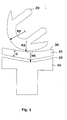
- Fig. 4 shows a perspective view of the Tibiagleitkomponente and Fig. 5 is a perspective view of the tibial base component.
- the coupling groove 60 is paired, along an imaginary symmetry axis.
- the coupling track 70 is designed as a complementary part, specifically with a tongue-like shape.
- the tongue-like extensions of the coupling track 70 can be inserted into the corresponding coupling groove and locked there.
- the locking in the inserted state can be made via a pin or bolt-like attachment, but also by a snap-in connection or the like.
Landscapes
- Health & Medical Sciences (AREA)
- Orthopedic Medicine & Surgery (AREA)
- Physical Education & Sports Medicine (AREA)
- Cardiology (AREA)
- Oral & Maxillofacial Surgery (AREA)
- Transplantation (AREA)
- Engineering & Computer Science (AREA)
- Biomedical Technology (AREA)
- Heart & Thoracic Surgery (AREA)
- Vascular Medicine (AREA)
- Life Sciences & Earth Sciences (AREA)
- Animal Behavior & Ethology (AREA)
- General Health & Medical Sciences (AREA)
- Public Health (AREA)
- Veterinary Medicine (AREA)
- Prostheses (AREA)
Abstract
Description
- Fig. 1
- eine beispielhafte Darstellung einer Femur- und Tibiakomponente in einem Sagittalebenenschnitt durch die Mitte einer Kondyle,
- Fig. 2
- eine beispielhafte Darstellung einer Tibiagleitkomponente in Verbindung mit einer Tibiabasiskomponente in einer detaillierteren Ansicht,
- Fig. 3a-c
- eine beispielhafte Darstellung eines Einbringvorganges der Tibiagleitkomponente in eine Anordnung aus Femur- und Tibiabasiskomponente in einem durch die Mitte einer Kondyle geführten Sagittalebenenschnitt;
- Fig. 4
- eine perspektivische Darstellung der Tibiagleitkomponente und
- Fig. 5
- eine perspektivische Darstellung der Tibiabasiskomponente.
Analog ist die Kopplungsbahn 70 als komplementäres Teil, und zwar mit beispielsweise zungenartiger Gestalt ausgeführt. Die zungenartigen Fortsätze der Kopplungsbahn 70 können in die entsprechende Kopplungsnut eingeführt und dort arretiert werden. Die Verriegelung im eingeschobenen Zustand kann über eine stift- oder bolzenartige Befestigung, aber auch durch eine Snap-in-Verbindung oder dergleichen vorgenommen werden.
- 10
- Tibiagleitkomponente
- 20
- Femurkomponente
- 30
- Tibiagleitfläche
- 40
- Tibiabasiskomponente
- 50
- Kopplungsfläche
- 60
- Kopplungsnut
- 70
- Kopplungsbahn
- 75
- femurale Kondyle
- D
- Dicke der Tibiagleitkomponente
- RF
- größter Femurradius
- RG
- Gleitflächenradius
- RK
- Kopplungsflächenradius
Claims (3)
- Tibiaplateaukomponente für eine Knieendoprothese, umfassend eine Tibiagleitkomponente (10) mit einer mit einer Femurkomponente (20) in gleitendem Kontakt stehenden Tibiagleitfläche (30) und eine in der Tibia verankerte, die Tibiagleitkomponente tragende Tibiabasiskomponente (40),
dadurch gekennzeichnet, dassdie Tibiagleitfläche (30) mindestens entlang eines Sagittalebenenschnittes eine Form eines Zylindermantelausschnittes aufweist, wobei der Gleitflächenradius (RG) des Zylindermantelabschnittes gleich oder größer dem größten Femurradius (RF) der Femurkomponente (20) ist undeine Kopplungsfläche (50) zwischen der Tibiagleitkomponente (10) und der Tibiabasiskomponente (40) die Form eines Zylindermantelabschnittes hat und einen Kopplungsflächenradius (RK) aufweist, dessen Größe mindestens gleich der Größe des um den Betrag der mittleren Dicke (D) der Tibiagleitkomponente erhöhten Gleitflächenradius (RG) ist. - Tibiaplateaukomponente nach Anspruch 1,
dadurch gekennzeichnet, dass
die Tibiagleitkomponente (10) und die Tibiabasiskomponente (40) über eine an der Tibiagleitkomponente oder der Tibiabasiskomponente eingearbeitete Kopplungsnut (60) in Verbindung mit an einer der jeweils anderen Komponente befindlichen Kopplungsbahn (70) zusammengefügt sind. - Tibiaplateaukomponente nach einem der Ansprüche 1 oder 2,
dadurch gekennzeichnet, dass
die Tibiagleitkomponente (10) und die Tibiabasiskomponente (40) im verbundenen Zustand miteinander durch eine Schnappkontur verrastet und/oder verschraubt sind.
Applications Claiming Priority (4)
| Application Number | Priority Date | Filing Date | Title |
|---|---|---|---|
| DE10348835 | 2003-10-21 | ||
| DE10348835 | 2003-10-21 | ||
| DE10361780 | 2003-12-31 | ||
| DE10361780A DE10361780B4 (de) | 2003-10-21 | 2003-12-31 | Tibiaplateaukomponente für eine Knieendoprothese |
Publications (2)
| Publication Number | Publication Date |
|---|---|
| EP1525862A2 true EP1525862A2 (de) | 2005-04-27 |
| EP1525862A3 EP1525862A3 (de) | 2005-12-28 |
Family
ID=34395063
Family Applications (1)
| Application Number | Title | Priority Date | Filing Date |
|---|---|---|---|
| EP04024984A Withdrawn EP1525862A3 (de) | 2003-10-21 | 2004-10-20 | Tibiaplateaukomponente für eine Knieendoprothese. |
Country Status (1)
| Country | Link |
|---|---|
| EP (1) | EP1525862A3 (de) |
Cited By (2)
| Publication number | Priority date | Publication date | Assignee | Title |
|---|---|---|---|---|
| EP2859866A1 (de) * | 2013-10-14 | 2015-04-15 | Euros | Tibiaimplantat einer Knieprothese, das einen Sockel und eine Stützplatte mit variabler Dicke umfasst, und Verfahren für deren Zusammenbau |
| AU2016209267B2 (en) * | 2015-01-21 | 2018-11-08 | Active Implants LLC | Partial unicompartmental system for partial knee replacement |
Family Cites Families (7)
| Publication number | Priority date | Publication date | Assignee | Title |
|---|---|---|---|---|
| US4224696A (en) * | 1978-09-08 | 1980-09-30 | Hexcel Corporation | Prosthetic knee |
| GB9102348D0 (en) * | 1991-02-04 | 1991-03-20 | Inst Of Orthopaedics The | Prosthesis for knee replacement |
| DE4202717C1 (de) * | 1991-12-11 | 1993-06-17 | Dietmar Prof. Dr. 3350 Kreiensen De Kubein-Meesenburg | |
| DE4140838C1 (de) * | 1991-12-11 | 1993-05-06 | Dietmar Prof. Dr. 3350 Kreiensen De Kubein-Meesenburg | |
| US5358530A (en) * | 1993-03-29 | 1994-10-25 | Zimmer, Inc. | Mobile bearing knee |
| DE59408522D1 (de) * | 1993-11-23 | 1999-08-26 | Gerber | System für die ausbildung einer kniegelenk-endoprothese |
| US6004351A (en) * | 1996-09-14 | 1999-12-21 | Mizuho Ika Kogyo Kabushiki Kaisha | Prosthetic knee joint |
-
2004
- 2004-10-20 EP EP04024984A patent/EP1525862A3/de not_active Withdrawn
Cited By (3)
| Publication number | Priority date | Publication date | Assignee | Title |
|---|---|---|---|---|
| EP2859866A1 (de) * | 2013-10-14 | 2015-04-15 | Euros | Tibiaimplantat einer Knieprothese, das einen Sockel und eine Stützplatte mit variabler Dicke umfasst, und Verfahren für deren Zusammenbau |
| FR3011733A1 (fr) * | 2013-10-14 | 2015-04-17 | Euros Sa | Implant tibial de prothese de genou comportant une embase et un plateau support a epaisseur variable et procede d'assemblage de ces derniers |
| AU2016209267B2 (en) * | 2015-01-21 | 2018-11-08 | Active Implants LLC | Partial unicompartmental system for partial knee replacement |
Also Published As
| Publication number | Publication date |
|---|---|
| EP1525862A3 (de) | 2005-12-28 |
Similar Documents
| Publication | Publication Date | Title |
|---|---|---|
| DE69833736T2 (de) | Drehbare Gelenkprothese mit axialer Fixierung | |
| EP1325718B1 (de) | Tibiakomponente einer Kniegelenkendoprothese | |
| DE69204201T2 (de) | Femurteil einer Kniegelenkprothese mit modularem Nocken und Schaft. | |
| DE69626006T2 (de) | Tibiale prothese | |
| DE68915981T2 (de) | Moduläre Knieprothese. | |
| DE3872685T2 (de) | Ellenbogengelenkprothese. | |
| DE60033876T2 (de) | Modularer tibialer Einsatz für ein prosthetisches System | |
| DE69922723T2 (de) | Knieprothese mit vier Gelenkflächen | |
| EP0913132B1 (de) | Kniegelenkprothese | |
| DE69832861T2 (de) | Gelenkprothesensystem mit einer in Längsrichtung verschlossenen drehbaren Komponente | |
| DE69825537T2 (de) | Gelenkprothese mit kontrollierter Drehbewegung | |
| EP0808619B1 (de) | Ellbogengelenk-Endoprothese | |
| EP0855173B1 (de) | Fixation eines keramischen Bauteils als Gleitkomponente in einem Femurteil | |
| DE69925100T2 (de) | Modulare Ellenbogenprothese | |
| DE60030233T2 (de) | Anteriorer lumbaler Zwischenwirbelfusionskäfig mit Befestigungsplatte | |
| DE60035716T2 (de) | Ellbogenprothese | |
| DE3787674T2 (de) | Modulsystem zur Fixierung des Femurs. | |
| DE69428640T2 (de) | Knieersatzprothese | |
| EP3137017B1 (de) | Kniegelenkendoprothese | |
| DE102007032150B4 (de) | Künstliches Meniskusteil und Kniegelenkprothese | |
| DE60033575T2 (de) | Gelenksprothese | |
| DE8901097U1 (de) | Prothetisches Kniegelenk mit verbesserter Bahnführung der patellaren Komponente | |
| DE2906458A1 (de) | Gelenkprothese | |
| DE102011002958A1 (de) | Modulares proximales Interphalangealgelenk | |
| DE9017245U1 (de) | Prothetische Lagerungsvorrichtung |
Legal Events
| Date | Code | Title | Description |
|---|---|---|---|
| PUAI | Public reference made under article 153(3) epc to a published international application that has entered the european phase |
Free format text: ORIGINAL CODE: 0009012 |
|
| AK | Designated contracting states |
Kind code of ref document: A2 Designated state(s): AT BE BG CH CY CZ DE DK EE ES FI FR GB GR HU IE IT LI LU MC NL PL PT RO SE SI SK TR |
|
| AX | Request for extension of the european patent |
Extension state: AL HR LT LV MK |
|
| PUAL | Search report despatched |
Free format text: ORIGINAL CODE: 0009013 |
|
| AK | Designated contracting states |
Kind code of ref document: A3 Designated state(s): AT BE BG CH CY CZ DE DK EE ES FI FR GB GR HU IE IT LI LU MC NL PL PT RO SE SI SK TR |
|
| AX | Request for extension of the european patent |
Extension state: AL HR LT LV MK |
|
| 17P | Request for examination filed |
Effective date: 20051214 |
|
| AKX | Designation fees paid |
Designated state(s): AT BE BG CH CY CZ DE DK EE ES FI FR GB GR HU IE IT LI LU MC NL PL PT RO SE SI SK TR |
|
| STAA | Information on the status of an ep patent application or granted ep patent |
Free format text: STATUS: THE APPLICATION IS DEEMED TO BE WITHDRAWN |
|
| 18D | Application deemed to be withdrawn |
Effective date: 20090501 |