EP1525861B1 - Femurteil für eine Hüftgelenkendoprothese - Google Patents
Femurteil für eine Hüftgelenkendoprothese Download PDFInfo
- Publication number
- EP1525861B1 EP1525861B1 EP04027208A EP04027208A EP1525861B1 EP 1525861 B1 EP1525861 B1 EP 1525861B1 EP 04027208 A EP04027208 A EP 04027208A EP 04027208 A EP04027208 A EP 04027208A EP 1525861 B1 EP1525861 B1 EP 1525861B1
- Authority
- EP
- European Patent Office
- Prior art keywords
- stem
- prosthesis
- inertia
- shaft
- femur
- Prior art date
- Legal status (The legal status is an assumption and is not a legal conclusion. Google has not performed a legal analysis and makes no representation as to the accuracy of the status listed.)
- Expired - Lifetime
Links
- 210000004394 hip joint Anatomy 0.000 title claims description 13
- 210000000689 upper leg Anatomy 0.000 claims abstract description 56
- 239000000463 material Substances 0.000 claims description 9
- 241000309551 Arthraxon hispidus Species 0.000 claims 1
- 230000001747 exhibiting effect Effects 0.000 claims 1
- 210000000988 bone and bone Anatomy 0.000 abstract description 21
- 238000011540 hip replacement Methods 0.000 abstract 1
- 239000007943 implant Substances 0.000 description 24
- 239000004568 cement Substances 0.000 description 22
- 230000035882 stress Effects 0.000 description 22
- 239000002639 bone cement Substances 0.000 description 16
- 238000002513 implantation Methods 0.000 description 14
- 210000001624 hip Anatomy 0.000 description 7
- 230000002980 postoperative effect Effects 0.000 description 5
- 238000002271 resection Methods 0.000 description 5
- 238000005452 bending Methods 0.000 description 4
- 238000013461 design Methods 0.000 description 4
- 239000002131 composite material Substances 0.000 description 3
- 230000000694 effects Effects 0.000 description 3
- 208000037099 Prosthesis Failure Diseases 0.000 description 2
- 229910001069 Ti alloy Inorganic materials 0.000 description 2
- 230000010072 bone remodeling Effects 0.000 description 2
- 230000001054 cortical effect Effects 0.000 description 2
- 208000006386 Bone Resorption Diseases 0.000 description 1
- WAIPAZQMEIHHTJ-UHFFFAOYSA-N [Cr].[Co] Chemical class [Cr].[Co] WAIPAZQMEIHHTJ-UHFFFAOYSA-N 0.000 description 1
- 230000006978 adaptation Effects 0.000 description 1
- 230000032683 aging Effects 0.000 description 1
- 229910045601 alloy Inorganic materials 0.000 description 1
- 239000000956 alloy Substances 0.000 description 1
- 238000004873 anchoring Methods 0.000 description 1
- 230000000712 assembly Effects 0.000 description 1
- 238000000429 assembly Methods 0.000 description 1
- 239000000560 biocompatible material Substances 0.000 description 1
- 230000015572 biosynthetic process Effects 0.000 description 1
- 230000024279 bone resorption Effects 0.000 description 1
- 230000009194 climbing Effects 0.000 description 1
- 230000000052 comparative effect Effects 0.000 description 1
- 230000006835 compression Effects 0.000 description 1
- 238000007906 compression Methods 0.000 description 1
- 238000010276 construction Methods 0.000 description 1
- 210000000501 femur body Anatomy 0.000 description 1
- 210000002436 femur neck Anatomy 0.000 description 1
- 239000000835 fiber Substances 0.000 description 1
- 230000000977 initiatory effect Effects 0.000 description 1
- 238000003780 insertion Methods 0.000 description 1
- 230000037431 insertion Effects 0.000 description 1
- 230000003993 interaction Effects 0.000 description 1
- 238000011835 investigation Methods 0.000 description 1
- 230000009191 jumping Effects 0.000 description 1
- 210000003127 knee Anatomy 0.000 description 1
- 230000007774 longterm Effects 0.000 description 1
- 230000010355 oscillation Effects 0.000 description 1
- 239000002245 particle Substances 0.000 description 1
- 229920003229 poly(methyl methacrylate) Polymers 0.000 description 1
- 239000004926 polymethyl methacrylate Substances 0.000 description 1
- 239000007779 soft material Substances 0.000 description 1
- 210000001694 thigh bone Anatomy 0.000 description 1
- 238000012546 transfer Methods 0.000 description 1
Images


Classifications
-
- A—HUMAN NECESSITIES
- A61—MEDICAL OR VETERINARY SCIENCE; HYGIENE
- A61F—FILTERS IMPLANTABLE INTO BLOOD VESSELS; PROSTHESES; DEVICES PROVIDING PATENCY TO, OR PREVENTING COLLAPSING OF, TUBULAR STRUCTURES OF THE BODY, e.g. STENTS; ORTHOPAEDIC, NURSING OR CONTRACEPTIVE DEVICES; FOMENTATION; TREATMENT OR PROTECTION OF EYES OR EARS; BANDAGES, DRESSINGS OR ABSORBENT PADS; FIRST-AID KITS
- A61F2/00—Filters implantable into blood vessels; Prostheses, i.e. artificial substitutes or replacements for parts of the body; Appliances for connecting them with the body; Devices providing patency to, or preventing collapsing of, tubular structures of the body, e.g. stents
- A61F2/02—Prostheses implantable into the body
- A61F2/30—Joints
- A61F2/32—Joints for the hip
- A61F2/36—Femoral heads ; Femoral endoprostheses
- A61F2/3662—Femoral shafts
-
- A—HUMAN NECESSITIES
- A61—MEDICAL OR VETERINARY SCIENCE; HYGIENE
- A61F—FILTERS IMPLANTABLE INTO BLOOD VESSELS; PROSTHESES; DEVICES PROVIDING PATENCY TO, OR PREVENTING COLLAPSING OF, TUBULAR STRUCTURES OF THE BODY, e.g. STENTS; ORTHOPAEDIC, NURSING OR CONTRACEPTIVE DEVICES; FOMENTATION; TREATMENT OR PROTECTION OF EYES OR EARS; BANDAGES, DRESSINGS OR ABSORBENT PADS; FIRST-AID KITS
- A61F2/00—Filters implantable into blood vessels; Prostheses, i.e. artificial substitutes or replacements for parts of the body; Appliances for connecting them with the body; Devices providing patency to, or preventing collapsing of, tubular structures of the body, e.g. stents
- A61F2/02—Prostheses implantable into the body
- A61F2/30—Joints
- A61F2/3094—Designing or manufacturing processes
- A61F2/30965—Reinforcing the prosthesis by embedding particles or fibres during moulding or dipping
-
- A—HUMAN NECESSITIES
- A61—MEDICAL OR VETERINARY SCIENCE; HYGIENE
- A61F—FILTERS IMPLANTABLE INTO BLOOD VESSELS; PROSTHESES; DEVICES PROVIDING PATENCY TO, OR PREVENTING COLLAPSING OF, TUBULAR STRUCTURES OF THE BODY, e.g. STENTS; ORTHOPAEDIC, NURSING OR CONTRACEPTIVE DEVICES; FOMENTATION; TREATMENT OR PROTECTION OF EYES OR EARS; BANDAGES, DRESSINGS OR ABSORBENT PADS; FIRST-AID KITS
- A61F2/00—Filters implantable into blood vessels; Prostheses, i.e. artificial substitutes or replacements for parts of the body; Appliances for connecting them with the body; Devices providing patency to, or preventing collapsing of, tubular structures of the body, e.g. stents
- A61F2/02—Prostheses implantable into the body
- A61F2/30—Joints
- A61F2/32—Joints for the hip
- A61F2/36—Femoral heads ; Femoral endoprostheses
-
- A—HUMAN NECESSITIES
- A61—MEDICAL OR VETERINARY SCIENCE; HYGIENE
- A61F—FILTERS IMPLANTABLE INTO BLOOD VESSELS; PROSTHESES; DEVICES PROVIDING PATENCY TO, OR PREVENTING COLLAPSING OF, TUBULAR STRUCTURES OF THE BODY, e.g. STENTS; ORTHOPAEDIC, NURSING OR CONTRACEPTIVE DEVICES; FOMENTATION; TREATMENT OR PROTECTION OF EYES OR EARS; BANDAGES, DRESSINGS OR ABSORBENT PADS; FIRST-AID KITS
- A61F2/00—Filters implantable into blood vessels; Prostheses, i.e. artificial substitutes or replacements for parts of the body; Appliances for connecting them with the body; Devices providing patency to, or preventing collapsing of, tubular structures of the body, e.g. stents
- A61F2/02—Prostheses implantable into the body
- A61F2/30—Joints
- A61F2/32—Joints for the hip
- A61F2/36—Femoral heads ; Femoral endoprostheses
- A61F2/3662—Femoral shafts
- A61F2/367—Proximal or metaphyseal parts of shafts
-
- A—HUMAN NECESSITIES
- A61—MEDICAL OR VETERINARY SCIENCE; HYGIENE
- A61F—FILTERS IMPLANTABLE INTO BLOOD VESSELS; PROSTHESES; DEVICES PROVIDING PATENCY TO, OR PREVENTING COLLAPSING OF, TUBULAR STRUCTURES OF THE BODY, e.g. STENTS; ORTHOPAEDIC, NURSING OR CONTRACEPTIVE DEVICES; FOMENTATION; TREATMENT OR PROTECTION OF EYES OR EARS; BANDAGES, DRESSINGS OR ABSORBENT PADS; FIRST-AID KITS
- A61F2/00—Filters implantable into blood vessels; Prostheses, i.e. artificial substitutes or replacements for parts of the body; Appliances for connecting them with the body; Devices providing patency to, or preventing collapsing of, tubular structures of the body, e.g. stents
- A61F2/02—Prostheses implantable into the body
- A61F2/30—Joints
- A61F2/32—Joints for the hip
- A61F2/36—Femoral heads ; Femoral endoprostheses
- A61F2/3662—Femoral shafts
- A61F2/3676—Distal or diaphyseal parts of shafts
-
- A—HUMAN NECESSITIES
- A61—MEDICAL OR VETERINARY SCIENCE; HYGIENE
- A61F—FILTERS IMPLANTABLE INTO BLOOD VESSELS; PROSTHESES; DEVICES PROVIDING PATENCY TO, OR PREVENTING COLLAPSING OF, TUBULAR STRUCTURES OF THE BODY, e.g. STENTS; ORTHOPAEDIC, NURSING OR CONTRACEPTIVE DEVICES; FOMENTATION; TREATMENT OR PROTECTION OF EYES OR EARS; BANDAGES, DRESSINGS OR ABSORBENT PADS; FIRST-AID KITS
- A61F2/00—Filters implantable into blood vessels; Prostheses, i.e. artificial substitutes or replacements for parts of the body; Appliances for connecting them with the body; Devices providing patency to, or preventing collapsing of, tubular structures of the body, e.g. stents
- A61F2/02—Prostheses implantable into the body
- A61F2/30—Joints
- A61F2002/30001—Additional features of subject-matter classified in A61F2/28, A61F2/30 and subgroups thereof
- A61F2002/30003—Material related properties of the prosthesis or of a coating on the prosthesis
- A61F2002/30004—Material related properties of the prosthesis or of a coating on the prosthesis the prosthesis being made from materials having different values of a given property at different locations within the same prosthesis
- A61F2002/30014—Material related properties of the prosthesis or of a coating on the prosthesis the prosthesis being made from materials having different values of a given property at different locations within the same prosthesis differing in elasticity, stiffness or compressibility
-
- A—HUMAN NECESSITIES
- A61—MEDICAL OR VETERINARY SCIENCE; HYGIENE
- A61F—FILTERS IMPLANTABLE INTO BLOOD VESSELS; PROSTHESES; DEVICES PROVIDING PATENCY TO, OR PREVENTING COLLAPSING OF, TUBULAR STRUCTURES OF THE BODY, e.g. STENTS; ORTHOPAEDIC, NURSING OR CONTRACEPTIVE DEVICES; FOMENTATION; TREATMENT OR PROTECTION OF EYES OR EARS; BANDAGES, DRESSINGS OR ABSORBENT PADS; FIRST-AID KITS
- A61F2/00—Filters implantable into blood vessels; Prostheses, i.e. artificial substitutes or replacements for parts of the body; Appliances for connecting them with the body; Devices providing patency to, or preventing collapsing of, tubular structures of the body, e.g. stents
- A61F2/02—Prostheses implantable into the body
- A61F2/30—Joints
- A61F2002/30001—Additional features of subject-matter classified in A61F2/28, A61F2/30 and subgroups thereof
- A61F2002/30003—Material related properties of the prosthesis or of a coating on the prosthesis
- A61F2002/30004—Material related properties of the prosthesis or of a coating on the prosthesis the prosthesis being made from materials having different values of a given property at different locations within the same prosthesis
- A61F2002/30016—Material related properties of the prosthesis or of a coating on the prosthesis the prosthesis being made from materials having different values of a given property at different locations within the same prosthesis differing in hardness, e.g. Vickers, Shore, Brinell
-
- A—HUMAN NECESSITIES
- A61—MEDICAL OR VETERINARY SCIENCE; HYGIENE
- A61F—FILTERS IMPLANTABLE INTO BLOOD VESSELS; PROSTHESES; DEVICES PROVIDING PATENCY TO, OR PREVENTING COLLAPSING OF, TUBULAR STRUCTURES OF THE BODY, e.g. STENTS; ORTHOPAEDIC, NURSING OR CONTRACEPTIVE DEVICES; FOMENTATION; TREATMENT OR PROTECTION OF EYES OR EARS; BANDAGES, DRESSINGS OR ABSORBENT PADS; FIRST-AID KITS
- A61F2/00—Filters implantable into blood vessels; Prostheses, i.e. artificial substitutes or replacements for parts of the body; Appliances for connecting them with the body; Devices providing patency to, or preventing collapsing of, tubular structures of the body, e.g. stents
- A61F2/02—Prostheses implantable into the body
- A61F2/30—Joints
- A61F2002/30001—Additional features of subject-matter classified in A61F2/28, A61F2/30 and subgroups thereof
- A61F2002/30108—Shapes
- A61F2002/3011—Cross-sections or two-dimensional shapes
- A61F2002/30112—Rounded shapes, e.g. with rounded corners
-
- A—HUMAN NECESSITIES
- A61—MEDICAL OR VETERINARY SCIENCE; HYGIENE
- A61F—FILTERS IMPLANTABLE INTO BLOOD VESSELS; PROSTHESES; DEVICES PROVIDING PATENCY TO, OR PREVENTING COLLAPSING OF, TUBULAR STRUCTURES OF THE BODY, e.g. STENTS; ORTHOPAEDIC, NURSING OR CONTRACEPTIVE DEVICES; FOMENTATION; TREATMENT OR PROTECTION OF EYES OR EARS; BANDAGES, DRESSINGS OR ABSORBENT PADS; FIRST-AID KITS
- A61F2/00—Filters implantable into blood vessels; Prostheses, i.e. artificial substitutes or replacements for parts of the body; Appliances for connecting them with the body; Devices providing patency to, or preventing collapsing of, tubular structures of the body, e.g. stents
- A61F2/02—Prostheses implantable into the body
- A61F2/30—Joints
- A61F2002/30001—Additional features of subject-matter classified in A61F2/28, A61F2/30 and subgroups thereof
- A61F2002/30108—Shapes
- A61F2002/3011—Cross-sections or two-dimensional shapes
- A61F2002/30112—Rounded shapes, e.g. with rounded corners
- A61F2002/30125—Rounded shapes, e.g. with rounded corners elliptical or oval
-
- A—HUMAN NECESSITIES
- A61—MEDICAL OR VETERINARY SCIENCE; HYGIENE
- A61F—FILTERS IMPLANTABLE INTO BLOOD VESSELS; PROSTHESES; DEVICES PROVIDING PATENCY TO, OR PREVENTING COLLAPSING OF, TUBULAR STRUCTURES OF THE BODY, e.g. STENTS; ORTHOPAEDIC, NURSING OR CONTRACEPTIVE DEVICES; FOMENTATION; TREATMENT OR PROTECTION OF EYES OR EARS; BANDAGES, DRESSINGS OR ABSORBENT PADS; FIRST-AID KITS
- A61F2/00—Filters implantable into blood vessels; Prostheses, i.e. artificial substitutes or replacements for parts of the body; Appliances for connecting them with the body; Devices providing patency to, or preventing collapsing of, tubular structures of the body, e.g. stents
- A61F2/02—Prostheses implantable into the body
- A61F2/30—Joints
- A61F2002/30001—Additional features of subject-matter classified in A61F2/28, A61F2/30 and subgroups thereof
- A61F2002/30108—Shapes
- A61F2002/3011—Cross-sections or two-dimensional shapes
- A61F2002/30138—Convex polygonal shapes
- A61F2002/30153—Convex polygonal shapes rectangular
-
- A—HUMAN NECESSITIES
- A61—MEDICAL OR VETERINARY SCIENCE; HYGIENE
- A61F—FILTERS IMPLANTABLE INTO BLOOD VESSELS; PROSTHESES; DEVICES PROVIDING PATENCY TO, OR PREVENTING COLLAPSING OF, TUBULAR STRUCTURES OF THE BODY, e.g. STENTS; ORTHOPAEDIC, NURSING OR CONTRACEPTIVE DEVICES; FOMENTATION; TREATMENT OR PROTECTION OF EYES OR EARS; BANDAGES, DRESSINGS OR ABSORBENT PADS; FIRST-AID KITS
- A61F2/00—Filters implantable into blood vessels; Prostheses, i.e. artificial substitutes or replacements for parts of the body; Appliances for connecting them with the body; Devices providing patency to, or preventing collapsing of, tubular structures of the body, e.g. stents
- A61F2/02—Prostheses implantable into the body
- A61F2/30—Joints
- A61F2002/30001—Additional features of subject-matter classified in A61F2/28, A61F2/30 and subgroups thereof
- A61F2002/30108—Shapes
- A61F2002/30199—Three-dimensional shapes
- A61F2002/30205—Three-dimensional shapes conical
- A61F2002/3021—Three-dimensional shapes conical frustoconical
-
- A—HUMAN NECESSITIES
- A61—MEDICAL OR VETERINARY SCIENCE; HYGIENE
- A61F—FILTERS IMPLANTABLE INTO BLOOD VESSELS; PROSTHESES; DEVICES PROVIDING PATENCY TO, OR PREVENTING COLLAPSING OF, TUBULAR STRUCTURES OF THE BODY, e.g. STENTS; ORTHOPAEDIC, NURSING OR CONTRACEPTIVE DEVICES; FOMENTATION; TREATMENT OR PROTECTION OF EYES OR EARS; BANDAGES, DRESSINGS OR ABSORBENT PADS; FIRST-AID KITS
- A61F2/00—Filters implantable into blood vessels; Prostheses, i.e. artificial substitutes or replacements for parts of the body; Appliances for connecting them with the body; Devices providing patency to, or preventing collapsing of, tubular structures of the body, e.g. stents
- A61F2/02—Prostheses implantable into the body
- A61F2/30—Joints
- A61F2002/30001—Additional features of subject-matter classified in A61F2/28, A61F2/30 and subgroups thereof
- A61F2002/30316—The prosthesis having different structural features at different locations within the same prosthesis; Connections between prosthetic parts; Special structural features of bone or joint prostheses not otherwise provided for
- A61F2002/30317—The prosthesis having different structural features at different locations within the same prosthesis
- A61F2002/30324—The prosthesis having different structural features at different locations within the same prosthesis differing in thickness
-
- A—HUMAN NECESSITIES
- A61—MEDICAL OR VETERINARY SCIENCE; HYGIENE
- A61F—FILTERS IMPLANTABLE INTO BLOOD VESSELS; PROSTHESES; DEVICES PROVIDING PATENCY TO, OR PREVENTING COLLAPSING OF, TUBULAR STRUCTURES OF THE BODY, e.g. STENTS; ORTHOPAEDIC, NURSING OR CONTRACEPTIVE DEVICES; FOMENTATION; TREATMENT OR PROTECTION OF EYES OR EARS; BANDAGES, DRESSINGS OR ABSORBENT PADS; FIRST-AID KITS
- A61F2/00—Filters implantable into blood vessels; Prostheses, i.e. artificial substitutes or replacements for parts of the body; Appliances for connecting them with the body; Devices providing patency to, or preventing collapsing of, tubular structures of the body, e.g. stents
- A61F2/02—Prostheses implantable into the body
- A61F2/30—Joints
- A61F2002/30001—Additional features of subject-matter classified in A61F2/28, A61F2/30 and subgroups thereof
- A61F2002/30316—The prosthesis having different structural features at different locations within the same prosthesis; Connections between prosthetic parts; Special structural features of bone or joint prostheses not otherwise provided for
- A61F2002/30535—Special structural features of bone or joint prostheses not otherwise provided for
- A61F2002/30593—Special structural features of bone or joint prostheses not otherwise provided for hollow
-
- A—HUMAN NECESSITIES
- A61—MEDICAL OR VETERINARY SCIENCE; HYGIENE
- A61F—FILTERS IMPLANTABLE INTO BLOOD VESSELS; PROSTHESES; DEVICES PROVIDING PATENCY TO, OR PREVENTING COLLAPSING OF, TUBULAR STRUCTURES OF THE BODY, e.g. STENTS; ORTHOPAEDIC, NURSING OR CONTRACEPTIVE DEVICES; FOMENTATION; TREATMENT OR PROTECTION OF EYES OR EARS; BANDAGES, DRESSINGS OR ABSORBENT PADS; FIRST-AID KITS
- A61F2/00—Filters implantable into blood vessels; Prostheses, i.e. artificial substitutes or replacements for parts of the body; Appliances for connecting them with the body; Devices providing patency to, or preventing collapsing of, tubular structures of the body, e.g. stents
- A61F2/02—Prostheses implantable into the body
- A61F2/30—Joints
- A61F2002/30001—Additional features of subject-matter classified in A61F2/28, A61F2/30 and subgroups thereof
- A61F2002/30316—The prosthesis having different structural features at different locations within the same prosthesis; Connections between prosthetic parts; Special structural features of bone or joint prostheses not otherwise provided for
- A61F2002/30535—Special structural features of bone or joint prostheses not otherwise provided for
- A61F2002/30604—Special structural features of bone or joint prostheses not otherwise provided for modular
- A61F2002/30606—Sets comprising both cemented and non-cemented endoprostheses
-
- A—HUMAN NECESSITIES
- A61—MEDICAL OR VETERINARY SCIENCE; HYGIENE
- A61F—FILTERS IMPLANTABLE INTO BLOOD VESSELS; PROSTHESES; DEVICES PROVIDING PATENCY TO, OR PREVENTING COLLAPSING OF, TUBULAR STRUCTURES OF THE BODY, e.g. STENTS; ORTHOPAEDIC, NURSING OR CONTRACEPTIVE DEVICES; FOMENTATION; TREATMENT OR PROTECTION OF EYES OR EARS; BANDAGES, DRESSINGS OR ABSORBENT PADS; FIRST-AID KITS
- A61F2/00—Filters implantable into blood vessels; Prostheses, i.e. artificial substitutes or replacements for parts of the body; Appliances for connecting them with the body; Devices providing patency to, or preventing collapsing of, tubular structures of the body, e.g. stents
- A61F2/02—Prostheses implantable into the body
- A61F2/30—Joints
- A61F2002/30001—Additional features of subject-matter classified in A61F2/28, A61F2/30 and subgroups thereof
- A61F2002/30667—Features concerning an interaction with the environment or a particular use of the prosthesis
- A61F2002/30708—Means for distinguishing between left-sided and right-sided devices, Sets comprising both left-sided and right-sided prosthetic parts
-
- A—HUMAN NECESSITIES
- A61—MEDICAL OR VETERINARY SCIENCE; HYGIENE
- A61F—FILTERS IMPLANTABLE INTO BLOOD VESSELS; PROSTHESES; DEVICES PROVIDING PATENCY TO, OR PREVENTING COLLAPSING OF, TUBULAR STRUCTURES OF THE BODY, e.g. STENTS; ORTHOPAEDIC, NURSING OR CONTRACEPTIVE DEVICES; FOMENTATION; TREATMENT OR PROTECTION OF EYES OR EARS; BANDAGES, DRESSINGS OR ABSORBENT PADS; FIRST-AID KITS
- A61F2/00—Filters implantable into blood vessels; Prostheses, i.e. artificial substitutes or replacements for parts of the body; Appliances for connecting them with the body; Devices providing patency to, or preventing collapsing of, tubular structures of the body, e.g. stents
- A61F2/02—Prostheses implantable into the body
- A61F2/30—Joints
- A61F2/30721—Accessories
- A61F2002/30733—Inserts placed into an endoprosthetic cavity, e.g. for modifying a material property
-
- A—HUMAN NECESSITIES
- A61—MEDICAL OR VETERINARY SCIENCE; HYGIENE
- A61F—FILTERS IMPLANTABLE INTO BLOOD VESSELS; PROSTHESES; DEVICES PROVIDING PATENCY TO, OR PREVENTING COLLAPSING OF, TUBULAR STRUCTURES OF THE BODY, e.g. STENTS; ORTHOPAEDIC, NURSING OR CONTRACEPTIVE DEVICES; FOMENTATION; TREATMENT OR PROTECTION OF EYES OR EARS; BANDAGES, DRESSINGS OR ABSORBENT PADS; FIRST-AID KITS
- A61F2/00—Filters implantable into blood vessels; Prostheses, i.e. artificial substitutes or replacements for parts of the body; Appliances for connecting them with the body; Devices providing patency to, or preventing collapsing of, tubular structures of the body, e.g. stents
- A61F2/02—Prostheses implantable into the body
- A61F2/30—Joints
- A61F2/30767—Special external or bone-contacting surface, e.g. coating for improving bone ingrowth
- A61F2/30771—Special external or bone-contacting surface, e.g. coating for improving bone ingrowth applied in original prostheses, e.g. holes or grooves
- A61F2002/3082—Grooves
- A61F2002/30827—Plurality of grooves
-
- A—HUMAN NECESSITIES
- A61—MEDICAL OR VETERINARY SCIENCE; HYGIENE
- A61F—FILTERS IMPLANTABLE INTO BLOOD VESSELS; PROSTHESES; DEVICES PROVIDING PATENCY TO, OR PREVENTING COLLAPSING OF, TUBULAR STRUCTURES OF THE BODY, e.g. STENTS; ORTHOPAEDIC, NURSING OR CONTRACEPTIVE DEVICES; FOMENTATION; TREATMENT OR PROTECTION OF EYES OR EARS; BANDAGES, DRESSINGS OR ABSORBENT PADS; FIRST-AID KITS
- A61F2/00—Filters implantable into blood vessels; Prostheses, i.e. artificial substitutes or replacements for parts of the body; Appliances for connecting them with the body; Devices providing patency to, or preventing collapsing of, tubular structures of the body, e.g. stents
- A61F2/02—Prostheses implantable into the body
- A61F2/30—Joints
- A61F2/32—Joints for the hip
- A61F2/36—Femoral heads ; Femoral endoprostheses
- A61F2/3609—Femoral heads or necks; Connections of endoprosthetic heads or necks to endoprosthetic femoral shafts
- A61F2002/3611—Heads or epiphyseal parts of femur
-
- A—HUMAN NECESSITIES
- A61—MEDICAL OR VETERINARY SCIENCE; HYGIENE
- A61F—FILTERS IMPLANTABLE INTO BLOOD VESSELS; PROSTHESES; DEVICES PROVIDING PATENCY TO, OR PREVENTING COLLAPSING OF, TUBULAR STRUCTURES OF THE BODY, e.g. STENTS; ORTHOPAEDIC, NURSING OR CONTRACEPTIVE DEVICES; FOMENTATION; TREATMENT OR PROTECTION OF EYES OR EARS; BANDAGES, DRESSINGS OR ABSORBENT PADS; FIRST-AID KITS
- A61F2/00—Filters implantable into blood vessels; Prostheses, i.e. artificial substitutes or replacements for parts of the body; Appliances for connecting them with the body; Devices providing patency to, or preventing collapsing of, tubular structures of the body, e.g. stents
- A61F2/02—Prostheses implantable into the body
- A61F2/30—Joints
- A61F2/32—Joints for the hip
- A61F2/36—Femoral heads ; Femoral endoprostheses
- A61F2/3609—Femoral heads or necks; Connections of endoprosthetic heads or necks to endoprosthetic femoral shafts
- A61F2002/3625—Necks
-
- A—HUMAN NECESSITIES
- A61—MEDICAL OR VETERINARY SCIENCE; HYGIENE
- A61F—FILTERS IMPLANTABLE INTO BLOOD VESSELS; PROSTHESES; DEVICES PROVIDING PATENCY TO, OR PREVENTING COLLAPSING OF, TUBULAR STRUCTURES OF THE BODY, e.g. STENTS; ORTHOPAEDIC, NURSING OR CONTRACEPTIVE DEVICES; FOMENTATION; TREATMENT OR PROTECTION OF EYES OR EARS; BANDAGES, DRESSINGS OR ABSORBENT PADS; FIRST-AID KITS
- A61F2/00—Filters implantable into blood vessels; Prostheses, i.e. artificial substitutes or replacements for parts of the body; Appliances for connecting them with the body; Devices providing patency to, or preventing collapsing of, tubular structures of the body, e.g. stents
- A61F2/02—Prostheses implantable into the body
- A61F2/30—Joints
- A61F2/32—Joints for the hip
- A61F2/36—Femoral heads ; Femoral endoprostheses
- A61F2/3662—Femoral shafts
- A61F2002/3678—Geometrical features
- A61F2002/3686—Geometrical features bent
- A61F2002/3688—Geometrical features bent with opposite proximal and distal curvatures, i.e. S-shaped shaft
-
- A—HUMAN NECESSITIES
- A61—MEDICAL OR VETERINARY SCIENCE; HYGIENE
- A61F—FILTERS IMPLANTABLE INTO BLOOD VESSELS; PROSTHESES; DEVICES PROVIDING PATENCY TO, OR PREVENTING COLLAPSING OF, TUBULAR STRUCTURES OF THE BODY, e.g. STENTS; ORTHOPAEDIC, NURSING OR CONTRACEPTIVE DEVICES; FOMENTATION; TREATMENT OR PROTECTION OF EYES OR EARS; BANDAGES, DRESSINGS OR ABSORBENT PADS; FIRST-AID KITS
- A61F2/00—Filters implantable into blood vessels; Prostheses, i.e. artificial substitutes or replacements for parts of the body; Appliances for connecting them with the body; Devices providing patency to, or preventing collapsing of, tubular structures of the body, e.g. stents
- A61F2/02—Prostheses implantable into the body
- A61F2/30—Joints
- A61F2/32—Joints for the hip
- A61F2/36—Femoral heads ; Femoral endoprostheses
- A61F2/3662—Femoral shafts
- A61F2002/3678—Geometrical features
- A61F2002/3698—Geometrical features twisted about the longitudinal axis of the shaft
-
- A—HUMAN NECESSITIES
- A61—MEDICAL OR VETERINARY SCIENCE; HYGIENE
- A61F—FILTERS IMPLANTABLE INTO BLOOD VESSELS; PROSTHESES; DEVICES PROVIDING PATENCY TO, OR PREVENTING COLLAPSING OF, TUBULAR STRUCTURES OF THE BODY, e.g. STENTS; ORTHOPAEDIC, NURSING OR CONTRACEPTIVE DEVICES; FOMENTATION; TREATMENT OR PROTECTION OF EYES OR EARS; BANDAGES, DRESSINGS OR ABSORBENT PADS; FIRST-AID KITS
- A61F2/00—Filters implantable into blood vessels; Prostheses, i.e. artificial substitutes or replacements for parts of the body; Appliances for connecting them with the body; Devices providing patency to, or preventing collapsing of, tubular structures of the body, e.g. stents
- A61F2/02—Prostheses implantable into the body
- A61F2/30—Joints
- A61F2/46—Special tools for implanting artificial joints
- A61F2002/4631—Special tools for implanting artificial joints the prosthesis being specially adapted for being cemented
-
- A—HUMAN NECESSITIES
- A61—MEDICAL OR VETERINARY SCIENCE; HYGIENE
- A61F—FILTERS IMPLANTABLE INTO BLOOD VESSELS; PROSTHESES; DEVICES PROVIDING PATENCY TO, OR PREVENTING COLLAPSING OF, TUBULAR STRUCTURES OF THE BODY, e.g. STENTS; ORTHOPAEDIC, NURSING OR CONTRACEPTIVE DEVICES; FOMENTATION; TREATMENT OR PROTECTION OF EYES OR EARS; BANDAGES, DRESSINGS OR ABSORBENT PADS; FIRST-AID KITS
- A61F2230/00—Geometry of prostheses classified in groups A61F2/00 - A61F2/26 or A61F2/82 or A61F9/00 or A61F11/00 or subgroups thereof
- A61F2230/0002—Two-dimensional shapes, e.g. cross-sections
- A61F2230/0004—Rounded shapes, e.g. with rounded corners
-
- A—HUMAN NECESSITIES
- A61—MEDICAL OR VETERINARY SCIENCE; HYGIENE
- A61F—FILTERS IMPLANTABLE INTO BLOOD VESSELS; PROSTHESES; DEVICES PROVIDING PATENCY TO, OR PREVENTING COLLAPSING OF, TUBULAR STRUCTURES OF THE BODY, e.g. STENTS; ORTHOPAEDIC, NURSING OR CONTRACEPTIVE DEVICES; FOMENTATION; TREATMENT OR PROTECTION OF EYES OR EARS; BANDAGES, DRESSINGS OR ABSORBENT PADS; FIRST-AID KITS
- A61F2230/00—Geometry of prostheses classified in groups A61F2/00 - A61F2/26 or A61F2/82 or A61F9/00 or A61F11/00 or subgroups thereof
- A61F2230/0002—Two-dimensional shapes, e.g. cross-sections
- A61F2230/0004—Rounded shapes, e.g. with rounded corners
- A61F2230/0008—Rounded shapes, e.g. with rounded corners elliptical or oval
-
- A—HUMAN NECESSITIES
- A61—MEDICAL OR VETERINARY SCIENCE; HYGIENE
- A61F—FILTERS IMPLANTABLE INTO BLOOD VESSELS; PROSTHESES; DEVICES PROVIDING PATENCY TO, OR PREVENTING COLLAPSING OF, TUBULAR STRUCTURES OF THE BODY, e.g. STENTS; ORTHOPAEDIC, NURSING OR CONTRACEPTIVE DEVICES; FOMENTATION; TREATMENT OR PROTECTION OF EYES OR EARS; BANDAGES, DRESSINGS OR ABSORBENT PADS; FIRST-AID KITS
- A61F2230/00—Geometry of prostheses classified in groups A61F2/00 - A61F2/26 or A61F2/82 or A61F9/00 or A61F11/00 or subgroups thereof
- A61F2230/0002—Two-dimensional shapes, e.g. cross-sections
- A61F2230/0017—Angular shapes
- A61F2230/0019—Angular shapes rectangular
-
- A—HUMAN NECESSITIES
- A61—MEDICAL OR VETERINARY SCIENCE; HYGIENE
- A61F—FILTERS IMPLANTABLE INTO BLOOD VESSELS; PROSTHESES; DEVICES PROVIDING PATENCY TO, OR PREVENTING COLLAPSING OF, TUBULAR STRUCTURES OF THE BODY, e.g. STENTS; ORTHOPAEDIC, NURSING OR CONTRACEPTIVE DEVICES; FOMENTATION; TREATMENT OR PROTECTION OF EYES OR EARS; BANDAGES, DRESSINGS OR ABSORBENT PADS; FIRST-AID KITS
- A61F2230/00—Geometry of prostheses classified in groups A61F2/00 - A61F2/26 or A61F2/82 or A61F9/00 or A61F11/00 or subgroups thereof
- A61F2230/0063—Three-dimensional shapes
- A61F2230/0067—Three-dimensional shapes conical
-
- A—HUMAN NECESSITIES
- A61—MEDICAL OR VETERINARY SCIENCE; HYGIENE
- A61F—FILTERS IMPLANTABLE INTO BLOOD VESSELS; PROSTHESES; DEVICES PROVIDING PATENCY TO, OR PREVENTING COLLAPSING OF, TUBULAR STRUCTURES OF THE BODY, e.g. STENTS; ORTHOPAEDIC, NURSING OR CONTRACEPTIVE DEVICES; FOMENTATION; TREATMENT OR PROTECTION OF EYES OR EARS; BANDAGES, DRESSINGS OR ABSORBENT PADS; FIRST-AID KITS
- A61F2250/00—Special features of prostheses classified in groups A61F2/00 - A61F2/26 or A61F2/82 or A61F9/00 or A61F11/00 or subgroups thereof
- A61F2250/0014—Special features of prostheses classified in groups A61F2/00 - A61F2/26 or A61F2/82 or A61F9/00 or A61F11/00 or subgroups thereof having different values of a given property or geometrical feature, e.g. mechanical property or material property, at different locations within the same prosthesis
- A61F2250/0018—Special features of prostheses classified in groups A61F2/00 - A61F2/26 or A61F2/82 or A61F9/00 or A61F11/00 or subgroups thereof having different values of a given property or geometrical feature, e.g. mechanical property or material property, at different locations within the same prosthesis differing in elasticity, stiffness or compressibility
-
- A—HUMAN NECESSITIES
- A61—MEDICAL OR VETERINARY SCIENCE; HYGIENE
- A61F—FILTERS IMPLANTABLE INTO BLOOD VESSELS; PROSTHESES; DEVICES PROVIDING PATENCY TO, OR PREVENTING COLLAPSING OF, TUBULAR STRUCTURES OF THE BODY, e.g. STENTS; ORTHOPAEDIC, NURSING OR CONTRACEPTIVE DEVICES; FOMENTATION; TREATMENT OR PROTECTION OF EYES OR EARS; BANDAGES, DRESSINGS OR ABSORBENT PADS; FIRST-AID KITS
- A61F2250/00—Special features of prostheses classified in groups A61F2/00 - A61F2/26 or A61F2/82 or A61F9/00 or A61F11/00 or subgroups thereof
- A61F2250/0014—Special features of prostheses classified in groups A61F2/00 - A61F2/26 or A61F2/82 or A61F9/00 or A61F11/00 or subgroups thereof having different values of a given property or geometrical feature, e.g. mechanical property or material property, at different locations within the same prosthesis
- A61F2250/0019—Special features of prostheses classified in groups A61F2/00 - A61F2/26 or A61F2/82 or A61F9/00 or A61F11/00 or subgroups thereof having different values of a given property or geometrical feature, e.g. mechanical property or material property, at different locations within the same prosthesis differing in hardness, e.g. Vickers, Shore, Brinell
-
- A—HUMAN NECESSITIES
- A61—MEDICAL OR VETERINARY SCIENCE; HYGIENE
- A61F—FILTERS IMPLANTABLE INTO BLOOD VESSELS; PROSTHESES; DEVICES PROVIDING PATENCY TO, OR PREVENTING COLLAPSING OF, TUBULAR STRUCTURES OF THE BODY, e.g. STENTS; ORTHOPAEDIC, NURSING OR CONTRACEPTIVE DEVICES; FOMENTATION; TREATMENT OR PROTECTION OF EYES OR EARS; BANDAGES, DRESSINGS OR ABSORBENT PADS; FIRST-AID KITS
- A61F2250/00—Special features of prostheses classified in groups A61F2/00 - A61F2/26 or A61F2/82 or A61F9/00 or A61F11/00 or subgroups thereof
- A61F2250/0014—Special features of prostheses classified in groups A61F2/00 - A61F2/26 or A61F2/82 or A61F9/00 or A61F11/00 or subgroups thereof having different values of a given property or geometrical feature, e.g. mechanical property or material property, at different locations within the same prosthesis
- A61F2250/0036—Special features of prostheses classified in groups A61F2/00 - A61F2/26 or A61F2/82 or A61F9/00 or A61F11/00 or subgroups thereof having different values of a given property or geometrical feature, e.g. mechanical property or material property, at different locations within the same prosthesis differing in thickness
-
- A—HUMAN NECESSITIES
- A61—MEDICAL OR VETERINARY SCIENCE; HYGIENE
- A61F—FILTERS IMPLANTABLE INTO BLOOD VESSELS; PROSTHESES; DEVICES PROVIDING PATENCY TO, OR PREVENTING COLLAPSING OF, TUBULAR STRUCTURES OF THE BODY, e.g. STENTS; ORTHOPAEDIC, NURSING OR CONTRACEPTIVE DEVICES; FOMENTATION; TREATMENT OR PROTECTION OF EYES OR EARS; BANDAGES, DRESSINGS OR ABSORBENT PADS; FIRST-AID KITS
- A61F2250/00—Special features of prostheses classified in groups A61F2/00 - A61F2/26 or A61F2/82 or A61F9/00 or A61F11/00 or subgroups thereof
- A61F2250/0058—Additional features; Implant or prostheses properties not otherwise provided for
- A61F2250/0084—Means for distinguishing between left-sided and right-sided devices; Sets comprising both left-sided and right-sided prosthetic parts
-
- A—HUMAN NECESSITIES
- A61—MEDICAL OR VETERINARY SCIENCE; HYGIENE
- A61F—FILTERS IMPLANTABLE INTO BLOOD VESSELS; PROSTHESES; DEVICES PROVIDING PATENCY TO, OR PREVENTING COLLAPSING OF, TUBULAR STRUCTURES OF THE BODY, e.g. STENTS; ORTHOPAEDIC, NURSING OR CONTRACEPTIVE DEVICES; FOMENTATION; TREATMENT OR PROTECTION OF EYES OR EARS; BANDAGES, DRESSINGS OR ABSORBENT PADS; FIRST-AID KITS
- A61F2310/00—Prostheses classified in A61F2/28 or A61F2/30 - A61F2/44 being constructed from or coated with a particular material
- A61F2310/00005—The prosthesis being constructed from a particular material
- A61F2310/00011—Metals or alloys
- A61F2310/00023—Titanium or titanium-based alloys, e.g. Ti-Ni alloys
-
- A—HUMAN NECESSITIES
- A61—MEDICAL OR VETERINARY SCIENCE; HYGIENE
- A61F—FILTERS IMPLANTABLE INTO BLOOD VESSELS; PROSTHESES; DEVICES PROVIDING PATENCY TO, OR PREVENTING COLLAPSING OF, TUBULAR STRUCTURES OF THE BODY, e.g. STENTS; ORTHOPAEDIC, NURSING OR CONTRACEPTIVE DEVICES; FOMENTATION; TREATMENT OR PROTECTION OF EYES OR EARS; BANDAGES, DRESSINGS OR ABSORBENT PADS; FIRST-AID KITS
- A61F2310/00—Prostheses classified in A61F2/28 or A61F2/30 - A61F2/44 being constructed from or coated with a particular material
- A61F2310/00005—The prosthesis being constructed from a particular material
- A61F2310/00011—Metals or alloys
- A61F2310/00029—Cobalt-based alloys, e.g. Co-Cr alloys or Vitallium
Definitions
- the invention relates to a femoral component for a hip joint endoprosthesis, wherein the femoral component has a condyle, a neck and a shaft and the shaft has a cross section changing along the shaft axis and in the AP (anterior-posterior) plane around an anterior point is curved.
- a hip joint endoprosthesis in which the conical shaft has longitudinally extending grooves.
- the groove profile is symmetrical to the center of the shank cross-section and the grooves extend without rotation over the entire length of the shank.
- This groove profile in conjunction with the conicity of the shank, results in rotation of the inertial axis system along the shank axis.
- the elastic behavior of the shaft should be better adapted to the anatomical conditions of the human femur bone, whereby the resorption of the bone due to stress shielding should be reduced.
- the rotation of the inertial axis system shown in Figures 3a to 3d of this document involves a rotation of the maximum principal axis of inertia of approximately + 20 ° with respect to posterior.
- a cementable hip joint prosthesis with an anatomically shaped shaft with a flange-like support collar and a plurality of longitudinal grooves is known.
- the longitudinal grooves serve the formation of cement webs and thus the increase of the rotational and torsional strength and can also be asymmetrical according to the drawing.
- a hip joint endoprosthesis is known, the shaft has in its upper part an increasingly oval from bottom to top cross-section, the tip after inside and the other end is directed outwards, and has a twist which consists in an increasing in the direction of the anteversion of the neck from bottom to top twisting. This is to allow accurate positioning of the prosthesis and, in particular, a reproduction of the anteversion exhibited by the femoral neck inherently and to prevent a variate dislocation of the femur.
- an anatomically shaped composite prosthesis is known whose elastic modulus approximates that of the adjacent cortical bone after implantation.
- hip prosthesis for anchoring in the femur, known with a leaf-like shaft, wherein the shaft tapers from the shoulder to the lower, distal end.
- This hip joint prosthesis comprises a neck intended for insertion of a condyle, which opens at an angle into the shaft, the shaft being wound on the upper, proximal region adjoining the shoulder.
- the curvature of the proximal region serves to conform to the medullary canal. Furthermore, this is intended to counteract the tilting of the shaft in the medullary canal during implantation and a more uniform thickness of the bone cement layer can be achieved.
- hip endoprostheses The problem of hip endoprostheses is the power flow in the thighbone (femur), which is greatly altered by the implantation of a prosthesis.
- the hip reaction force becomes the femoral head initiated and derived over the relatively firm edge (cortical bone) of the femur to the knee.
- the inner areas of the femur (medullary canal, cancellous bone) are hardly loaded in this configuration.
- a less rigid prosthesis can counteract this effect to some extent in that the implant allows for greater deformation and thus relieves the surrounding bone much less, i. more heavily loaded than a stiffer prosthesis.
- the prosthesis must have the same strength as the healthy bone previously used to support the hip reaction force, with the result that a stiff load-bearing implant is now located in the originally soft and barely loaded medullary cavity and cancellous bone area.
- the bone cement (a PMMA) is sensitive to alternating loads, the higher the elastic the implant is designed.
- the long-term stability of the cement is thus determined by the amplitude of the load, the number of oscillations [(1-3 Mill.) / Year] and additionally influenced by signs of aging of the cement itself.
- the bone cement should therefore be preserved as much as possible. It follows that a desired additional load in the femur, ie a reduced stress shielding, usually leads to an undesirable additional burden of the bone cement.
- the burdens of the postoperative femur is therefore desirable on the one hand to prevent aseptic prosthesis loosening, on the other hand easily leads to excessive stress on the bone cement.
- the invention has for its object to delay the loosening of the implanted hip stem.
- the object is solved by the features of claim 1.
- this task is u.s. achieved in that at least in a longitudinal portion of the femoral component, the maximum principal axis of inertia is not aligned posteriorly.
- the deviation from the posterior orientation is ⁇ 10 to 30 °.
- the change in the shaft cross-section is such that the direction of its main axes of inertia rotates along the shaft.
- the prosthesis stem has a direction of the major axes of the surface inertial systems that changes along the longitudinal axis of the prosthesis.
- the change is defined by defining angles between a fixed reference axis system and the major axes of the plane inertial systems. These angles can be both negative and positive and are preferably between 10 and 30 °.
- the orientation of the principal axis of inertia of the femur changes along the axis of the femur.
- the change in the orientation of the principal axes of inertia of the endoprosthesis femoral component according to the invention can be adapted to this at least in part. Which solution is chosen in an individual case, the surgeon must decide. With the invention, he has a greater choice to the optimum in each case compromise to find between sparing the bone cement and reducing stress shielding.
- the stress shielding can also be controlled by the material selection.
- a relatively soft material eg, a titanium alloy, reduces stress shielding more than a rigid material, eg, a cobalt-chromium alloy.
- Major axes of inertia play a role as a mechanical variable when bending occurs.
- a main inertia axis system always has a maximum and a minimum inertia axis. These characterize those axes which cause a maximum moment of resistance (maximum principal axis of inertia) or a minimum moment of resistance (minimum principal axis of inertia) through this surface when the cross-sectional area around these axes is bent.
- the femur like most bones, etc. bent, and there is a system of principal axes of inertia in the femur. For each femoral cross section there is thus a maximum and a minimum principal axis of inertia.
- the bending load of the femur essentially determines the orientations of the main axis systems.
- the system of inertial axes of the cross-sections of the implant superimposes the predetermined system of the femur.
- New main axis systems are established in the femoral / implant composite system. Apart from the incoming stiffening, the reduction of the bending strain on the peri-implant bone tissue and the altered force flow, with partial or total loss of stress in certain areas of the femur, there are two extreme situations with respect to the major axis systems:
- the maximum principal axis of inertia of the prosthesis is as directed as the maximum principal axis of inertia of the femur (viewed cross-sectionally). This means that the original local stiff and less stiff regions in the femur are preserved in the composite system. The load distribution is similar to that in the femur without an implant and the resulting stress shielding of the bone tissue is reduced.
- the maximum principal axis of inertia of the prosthesis is as directed as the minimum principal axis of inertia of the femur.
- the originally existing stiff and weak regions of the femur are changed and the weak areas of the femur are stiffened by the implant and vice versa. This means increased stress shielding.
- the difference between maximum and minimum resistance moments of the surface becomes smaller, which means a more homogeneous load transfer into the bone cement.
- the maximum principal axis of inertia is often directed posteriorly by design. If, in the case of a cemented prosthesis stem, first and foremost the bone cement is to be preserved, then the alignment may be desired.
- the maximum main axis of inertia for example, according to a sine function between 0 and n / 2 along the shaft axis change by up to 30 ° to a posterior-medial orientation.
- the direction of the minimum principal axis of inertia of the shaft cross-section then has approximately the direction of the maximum principal axis of inertia of the femur in the distal region.
- a femoral component may be used in which the maximum principal axis of inertia is directed posteriorly at the upper end and corresponding to a sinusoidal function between 0 and ⁇ / 2 along the shaft axis and rotates up to 30 ° in the posterior-lateral direction.
- the optimized prosthesis system achieves a hitherto impossible combination of less relief of the postoperative femur and less stress on the bone cement. That the stress shielding that occurs as a result of implantation is only reduced to such an extent that unacceptably high cement loads do not occur.
- the lifetime of the implant can be lengthened compared to the invention by matching the directions of the maximum principal axis of inertia of the femoral component of the prosthesis and the femur as far as possible.
- a cementless prosthesis stem no cement load needs to be taken into account, so that there is a greater latitude for the course of the main axes of inertia along the prosthesis shaft.
- the maximum main axis of inertia along the prosthesis shaft can rotate in the posterior-lateral direction in accordance with a sine function between 0 and n / 2.
- a higher load on the femur is intended, then the maximum main axis of inertia along the prosthesis shaft can rotate in the posterior-lateral direction in accordance with a sine function between 0 and n / 2.
- a lower relief of the postoperative femur That is, the stress-shielding occurring as a result of the implantation is reduced.
- the maximum principal axes of inertia of cross sections of the femur in the resection plane show predominantly in the lateral-posterior direction.
- anterior and / or posterior grooves or similar notches are provided in the surface of the shaft for non-inventive prostheses.
- a groove is provided in the posterior-lateral area and / or in the anterior-medial area of the shaft surface.
- the shaft is doubly curved in the AP plane (S-curve), the proximal shaft portion having an anterior center of curvature and a radius of curvature in the range of 250 mm ⁇ 100 mm, and the distal shaft portion having a posterior center of curvature and a radius of curvature in the range of> 250mm, especially 350mm ⁇ 100mm.
- the curvature of the distal region is thus usually smaller than that of the proximal region and can also be completely eliminated. These are not consistently constant curvatures, but the curvatures vary over these areas.
- the variable span covers both the anatomically different femurs and the different radii of curvature in the proximal and distal regions and the different prosthesis sizes.
- the prosthesis stem has an S-curve and at the same time the maximum principal axes of inertia of the stem cross-sections are not in one plane.
- This embodiment of the femoral part according to the invention is used in particular for the cemented implantation.
- the S-curvature results in a more precise adaptation of the prosthesis stem to the natural curvature of the femur, whereby the individual areas of the cement have a more uniform thickness and are therefore more evenly loaded.
- the femoral component according to the invention is made of a titanium alloy in a cementless implantation and of another biocompatible material in a cemented implantation, e.g. a CoCrMo alloy.
- Figs. 1 and 2 show the femoral part of a hip joint endoprosthesis for the right hip joint.
- the femoral component consists of a shaft 10 which carries at its upper end on a neck 11 a condyle 12.
- the shaft 10 is curved in an S-shape in the AP plane.
- the proximal shaft region has an anterior center of curvature Mp, while the distal shaft region is straight or has a posterior center of curvature Md.
- the curvature is not uniform and is smaller in the distal region than in the proximal region.
- the radius of curvature is between 150 and 350 mm and in the distal region between 250 mm and m. Typical values are 250 or 350 mm.
- shaft curvature in the AP plane is to better fit the implant to the curved course of the medullary canal. Furthermore, the tilting of the shaft in the medullary canal during implantation is counteracted and a more homogeneous distribution of the bone cement is achieved.
- FIG. 1 shows a right femoral element not according to the invention, in which the maximum principal axis of inertia is directed posteriorly at the proximal end and rotates posteriorally along the shaft axis.
- Such a femoral component can be used in cementless and cemented prosthetic systems where the emphasis is on reducing stress shielding.
- the cement load is relatively high.
- Fig. 2 shows a right femoral component according to the invention, in which the maximum principal axis of inertia of the shaft is likewise directed posteriorly at the proximal end, but rotates posteriorly along the shaft axis.
- a femoral component can be used in a cemented prosthesis system when emphasis is placed on relieving the cement and less on reducing stress shielding.
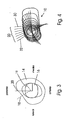
- FIG. 3 shows, in section, a right femur 14 with inserted conventional implant 16.
- Investigations on a femora have shown that the maximum principal axis of inertia 18 points predominantly in the lateral-posterior direction.
- the maximum principal axis of inertia 20 of the shaft prosthesis of the conventional implant 16 points in the posterior direction.
- This discrepancy between the maximum principal axis of inertia of the femoral component of the prosthesis and the minimum principal axis of inertia of the femur results in unfavorable loading of the bone cement in cemented implants. It has been found that reducing the angle between the maximum principal axis of inertia 20 of the implant 16 and the minimum principal axis of inertia 19 of the femur reduces the stress on the bone cement.
- the shank cross-sections have along the length of the shank 10 principal axes of inertia 20 which are not parallel to one another, but deviate from each other in their direction. The deviation is such that the maximum principal axes of inertia 20 of the implant do not lie in the AP plane but extend at an angle to one another.
- the directionally variable main axis system of the prosthesis shaft 10 has a rotation of the shaft cross sections around the Shank axis on.
- the maximum principal axis of inertia is directed posteriorly, so that in this respect it coincides with a conventional implant 16.
- the maximum principal axis of inertia of the femoral part according to the invention rotates by up to about 30 °. The rotation increases accordingly about a sine function in the range of 0 to n / 2.
- the direction of the maximum principal axis of inertia 20 of the prosthesis shaft 10 can be adapted to the direction of the minimum principal axis of inertia of the femoral cross-section in accordance with the aforementioned sine function.
- this corresponds to the rotation of a right-handed thread and, in the case of the left prosthesis stem, the rotation of a left-handed thread.
- the interaction forces between the femur and the prosthesis stem should be increased in order to avoid the otherwise occurring resorption of the relieving bone tissue (stress shielding).
- stress shielding Even with cemented prosthetic stems, more emphasis is placed on reducing stress-shielding than relieving the cement.
- the direction of the maximum principal axis of inertia then shows at the proximal end of the prosthesis shaft 10 e.g. by design again in the posterior direction. Towards the distal end it rotates according to a sinus function in the range of 0 to n / 2 by up to 30 ° in the lateral direction. The rotation is therefore left-handed on the right-hand prosthesis stem and right-handed on the left-hand prosthesis stem.
- Fig. 4 shows - viewed from above - the direction of the two main axes of inertia for cross sections at different points along the prosthesis shaft 10.
- the prosthesis shaft 10 is assumed to be straight, ie the curvature in the AP plane is not shown.
- the maximum principal axis of inertia is aligned with line 30. This orientation then rotates towards the distal end, then to line 32.
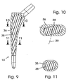
- the prosthesis stem 10 has a more or less pronounced oval cross-section, which is symmetrical in each case to the principal axes of inertia, wherein the prosthesis stem is homogeneous in the interior.
- the surface of the femoral component is smooth, ie, approximately oval and free of reentrant and protruding contours, and rotation of the main axis of inertia is achieved solely by rotation of the cross sections along the prosthesis stem.
- the surface may be porous to promote ingrowth of the bone tissue.
- the surface must not be smooth in non-inventive prostheses and the direction of the main axes of inertia can also be achieved by changes in the outer contour of the prosthesis cross-section, eg the introduction of radii, grooves or notches, which lead to a rotation of the main axes of inertia along the prosthesis shaft 10.
- Figures 5 to 8 show a femoral stem having grooves 34 which are asymmetrically provided posteriorly and anteriorly on the surface of the femoral stem and whose major axes of inertia are right-handed in rotation along the femoral stem.
- the grooves 34 change the cross-section of the shaft 10 in such a way that already in the resection plane the maximum principal axis of inertia is rotated by a few degrees in the posterior-lateral direction and is thus already aligned here approximately corresponding to the maximum principal axis of inertia of the femur.
- the maximum principal axis of inertia of the shaft 10 then rotates corresponding to that of the femur, the angle of rotation being smaller here, since the maximum principal axis of inertia at the proximal end is already largely aligned with that of the femur.
- the wall thickness at the distal end of the prosthesis stem is approximately uniform, while it is different at the proximal end on the circumference.
- the cross section of the prosthesis stem is strongly oval at the proximal end.
- the inner portion 38 has an oval outline, but rotated with respect to the outer contour of the prosthesis shaft 10, so that the maximum principal axis of inertia in the resection plane is rotated from the posterior direction by several degrees in the lateral direction.
- rotation of the main inertia axis system can also be achieved by the use of anisotropic, fiber or particle reinforced materials.
Landscapes
- Health & Medical Sciences (AREA)
- Orthopedic Medicine & Surgery (AREA)
- Cardiology (AREA)
- Oral & Maxillofacial Surgery (AREA)
- Transplantation (AREA)
- Engineering & Computer Science (AREA)
- Biomedical Technology (AREA)
- Heart & Thoracic Surgery (AREA)
- Vascular Medicine (AREA)
- Life Sciences & Earth Sciences (AREA)
- Animal Behavior & Ethology (AREA)
- General Health & Medical Sciences (AREA)
- Public Health (AREA)
- Veterinary Medicine (AREA)
- Prostheses (AREA)
Description
- Die Erfindung betrifft ein Femurteil für eine Hüftgelenkendoprothese, wobei das Femurteil einen Gelenkkopf, einen Hals und einen Schaft aufweist und der Schaft einen sich längs der Schaftachse verändernden Querschnitt aufweist und in der AP-Ebene (Anterior-Posterior-Ebene) um einen anterior gelegenen Punkt gekrümmt ist.
- Aus
DE-C1-199 35 289 ist eine Hüftgelenkendoprothese bekannt, bei der der konische Schaft in Längsrichtung verlaufende Nuten aufweist. Das Nutenprofil ist symmetrisch zum Mittelpunkt des Schaftquerschnitts und die Nuten verlaufen ohne Rotation über die gesamte Länge des Schaftes. Dieses Nutenprofil führt in Verbindung mit der Konizität des Schaftes zu einer Drehung des Trägheitsachsensystems längs der Schaftachse. Dadurch soll das Elastizitätsverhalten des Schaftes besser an die anatomischen Gegebenheiten des menschlichen Femurknochens angepasst werden, wodurch die Resorption des Knochens infolge Stress-Shielding verringert werden soll. Die in den Fig. 3a bis 3d dieser Druckschrift dargestellte Drehung des Trägheitsachsensystems beinhaltet eine Drehung der maximalen Hauptträgheitsachse von etwa +20• gegenüber posterior. - Aus
DE-A-38 29 361 ist eine einzementierbare Hüftgelenkendoprothese mit einem anatomisch geformten Schaft mit einem flanschartigen Stützkragen und mehreren Längsrillen bekannt. Die Längsrillen dienen der Bildung von Zementstegen und damit der Erhöhung der Rotations- und Torsionsfestigkeit und können nach der Zeichnung auch unsymmetrisch verlaufen. - Aus
DE-T2-691 03 895 ist eine Hüftgelenkendoprothese bekannt, deren Schaft in seinem oberen Teil einen von unten nach oben zunehmend ovalen Querschnitt aufweist, wobei die Spitze nach innen und das andere Ende nach außen gerichtet ist, und eine Verwindung aufweist, die in einer in Richtung der Anteversion des Halses von unten nach oben zunehmenden Verdrehung besteht. Dadurch soll eine genaue Positionierung der Prothese und insbesondere eine Wiedergabe der Anteversion ermöglicht werden, die der Femurhals von Natur aus aufweist, und soll eine varale Versetzung des Femur verhindert werden. - Aus
DE-U-92 90 043 ist eine anatomisch geformte Prothese aus Verbundmaterialien bekannt, deren Elastizitätsmodul dem des benachbarten kortikalen Knochens nach der Implantation angenähert ist. - Aus
DE-U-299 23 205 ist ein einzementierbares Prothesenteil mit einem Kragen und einem anatomisch angepassten Schaft bekannt, wobei der proximale Schaftabschnitt eine Verwindung aufweist. Dadurch soll eine gleichmäßige, den anatomischen Verhältnissen angepasste Krafteinleitung erzielt werden. - Aus
EP-A-0 695 540 ist eine Hüftgelenkendoprothese bekannt mit einer Drehung der Symmetrieebene der Schaftquerschnitte im oberen Bereich des Schaftes um etwa 10. Der Hals kann getrennt von dem Schaft hergestellt werden und mit seinem eigenen Anteversionswinkel an den Schaft angepasst sein, so dass dieser Anteversionswinkel mit dem Antetorsionswinkel des Schaftes zusammenwirkt. - Aus der
EP-A-0 528 284 ist eine Hüftgelenkprothese für die Verankerung im Femur, mit einem blattartigen Schaft bekannt, wobei der Schaft sich von der Schulter zum unteren, distalen Ende hin verjüngt. Diese Hüftgelenkprothese umfasst einen zum Aufstecken eines Gelenkkopfs bestimmten, unter einem Winkel in den Schaft mündenden Hals, wobei der Schaft am an die Schulter anschließenden oberen, proximalen Bereich verwunden ist. - Bei diesen Femurteilen nach dem Stand der Technik dient die Krümmung des proximalen Bereichs der Anpassung an den Markraumkanal. Weiterhin soll dadurch dem Verkanten des Schaftes im Markraumkanal während der Implantation entgegengewirkt werden und eine gleichförmigere Stärke der Knochenzementschicht erzielt werden.
- Die Problematik von Hüftendoprothesen ist der durch die Implantation einer Prothese sehr stark veränderte Kraftfluss im Oberschenkelknochen (Femur). Im intakten, prothetisch nicht versorgten System wird die Hüftreaktionskraft in den Femurkopf eingeleitet und über den relativ festen Rand (Kortikalis) des Femurs zum Knie abgeleitet. Die inneren Bereiche des Femurs (Markraum, Spongiosa) werden in dieser Konfiguration kaum belastet.
- Die negativen Effekte einer implantierten Prothese auf den Femur lassen sich folgendermaßen formulieren:
- Der überwiegende Teil der Hüftreaktionskraft wird über Prothesenkopf, -hals, sowie -schaft in das umgebende Knochengewebe geleitet. Ein Teil der Last wird bis zur Prothesenspitze geleitet und gelangt erst dort in den Femur. Das bedeutet eine starke Entlastung des periimplantären Knochens insbesondere im gesamten proximalen Bereich (stress-shielding). Da der Knochen dem natürlichen Gesetz der Effizienz unterworfen ist, resorbiert er entlastetes Knochengewebe (postoperatives Bone Remodeling). In der Folge verliert das Implantat sein stabiles Lager in der Knochenumgebung und lockert sich (aseptische Prothesenlockerung).
- Eine weniger steife Prothese kann diesem Effekt in einem gewissen Maße insofern entgegenwirken, als das Implantat eine höhere Verformung zulässt und somit den umgebenden Knochen wesentlich weniger entlastet, d.h. stärker belastet, als eine steifere Prothese. Restriktionen an die konstruktive Gestaltung einer Prothese hinsichtlich ihrer Elastizität lassen diesen Überlegungen aber wenig Raum. So muss beispielsweise die Prothese die gleiche Festigkeit aufbringen, wie zuvor der gesunde Knochen um die Hüftreaktionskraft zu tragen, mit der Folge, dass sich nun im ursprünglich weichen und kaum belasteten Markraum und Spongiosabereich des Knochen ein steifes lasttragendes Implantat befindet.
- Bei zementierten Prothesensystem kommt das Problem der Belastung des Knochenzements hinzu. Der Knochenzement (ein PMMA) reagiert empfindlich auf Wechselbelastungen, die um so höher sind, je elastischer das Implantat ausgelegt ist. Die Langzeitstabilität des Zement wird also von der Amplitude der Belastung, der Anzahl der Schwingungen [(1-3 Mill.)/Jahr] und zusätzlich von Alterungserscheinungen des Zementes selbst beeinflusst. Um eine lange Standzeit des Implantats zu gewährleisten ist somit der Knochenzement möglichst zu schonen. Daraus folgt, dass eine gewünschte Mehrbelastung im Femur, also ein verringertes Stress-Shielding, in der Regel zu einer unerwünschten Mehrbelastung des Knochenzements führt. Die Belastungen des postoperativen Femurs ist also einerseits erwünscht, um einer aseptischen Prothesenlockerung vorzubeugen, führt anderseits leicht zu einer übermäßigen Beanspruchung des Knochenzements.
- Der Erfindung liegt die Aufgabe zugrunde, das Lockern des implantierten Hüftgelenkschafts zu verzögern.
Die Aufgabe wird durch die Merkmale des Anspruchs 1 gelöst. - Erfindungsgemäß wird diese Aufgabe u.s. dadurch gelöst, dass zumindest in einem Längsabschnitt des Femurteils die maximale Hauptträgheitsachse nicht posterior ausgerichtet ist.
- Erfindungsgemäß beträgt die Abweichung von der posterioren Ausrichtung ± 10 bis 30°.
- Die Änderung des Schaftquerschnitts ist derart, daß sich die Richtung seiner Hauptträgheitsachsen längs des Schaftes dreht. Der Prothesenschaft hat eine sich entlang der Prothesenlängsachse verändernde Richtung der Hauptachsen der Flächenträgheitssysteme. Die Änderung ist durch die Festlegung von Winkeln zwischen einem festen Bezugsachsensystem und den Hauptachsen der Flächenträgheitssysteme definiert. Diese Winkel können sowohl negativ als auch positiv sein und liegen vorzugsweise zwischen 10 und 30°.
- Die Ausrichtung der Hauptträgheitsachsen des Femurs ändert sich längs der Achse des Femurs. Die Änderung der Ausrichtung der Hauptträgheitsachsen des erfindungsgemäßen Endoprothesen-Femurteils kann dem zumindest teilweise angepasst werden. Welche Lösung im Einzelfall gewählt wird, muss der Operateur entscheiden. Durch die Erfindung hat er eine größere Auswahlmöglichkeit, um den im Einzelfall optimalen Kompromiss zwischen Schonung des Knochenzements und Verringerung des Stress-Shielding zu finden. Das Stress-Shielding lässt sich dabei auch durch die Materialauswahl steuern. Ein relativ weiches Material, z.B. eine Titanlegierung, verringert das Stress-Shielding stärker als ein steifes Material, z.B. eine Kobalt-Chrom-Legierung.
- Zur Erklärung des durch die Erfindung erzielten Effektes werden nachfolgend die Systeme der Hauptträgheitsachsen des natürlichen Femur und des Implantats betrachtet:
- Hauptträgheitsachsen spielen als mechanische Größe eine Rolle, wenn Biegung auftritt. Ein Hauptträgheitsachsensystem weist immer eine maximale und eine minimale Trägheitsachse auf. Diese charakterisieren jene Achsen, welche bei einer Biegung der Querschnittsfläche um diese Achsen ein maximales Widerstandsmoment (maximale Hauptträgheitsachse) bzw. ein minimales Widerstandsmoment (minimale Hauptträgheitsachse) durch diese Fläche hervorrufen. Der Femur wird wie die meisten Knochen u.a. auf Biegung beansprucht und im Femur existiert ein System von Hauptträgheitsachsen. Für jeden Femurquerschnitt existiert also eine maximale und eine minimale Hauptträgheitsachse.
- Überlagert man alle Belastungen, denen der Femur ausgesetzt ist (Treppensteigen, Gehen, Laufen, Springen usw.), zu einer einzigen, mehrachsigen Belastung, so bestimmt die Biegebelastung des Femur im Wesentlichen die Orientierungen der Hauptachsensysteme.
- Bei der Implantation eines Prothesenschaftes überlagert das System von Trägheitsachsen der Querschnitte des Implantats das vorgegebene System des Femur. Es stellen sich im Verbundsystem Femur/Implantat neue Hauptachsensysteme ein. Abgesehen von der eintretenden Versteifung, der Verringerung der Biegebelastung des periimplantären Knochengewebes und dem veränderten Kraftfluss, mit teilweisem oder völligem Verlust der Belastung in bestimmten Bereichen des Femur, bestehen zwei Extremsituationen hinsichtlich der Hauptachsensysteme:
- 1. Die maximale Hauptträgheitsachse der Prothese ist so gerichtet wie die maximale Hauptträgheitsachse des Femur (querschnittsweise betrachtet). Das bedeutet, die ursprünglich bestehenden lokalen steifen und weniger steifen Regionen im Femur bleiben auch im Verbundsystem erhalten. Die Belastungsverteilung ist also ähnlich wie im Femur ohne Implantat und das resultierende Stress-Shielding des Knochengewebes ist verringert.
- Für ein einzementiertes Implantat ist das Vorhandensein von Regionen unterschiedlicher Belastung jedoch ungünstig. Die Zementbelastung ist immer dann am geringsten, wenn die Belastung möglichst homogen in den Zement eingeleitet wird. Existieren aber nun unterschiedliche Steifigkeiten ist das nicht möglich. In den Bereichen geringer Steifigkeit ist die Zementbelastung am höchsten.
- 2. Die maximale Hauptträgheitsachse der Prothese ist so gerichtet wie die minimale Hauptträgheitsachse des Femur. Die ursprünglich bestehenden steifen und schwachen Regionen des Femur werden verändert und die schwachen Bereiche des Femur werden durch das Implantat versteift und umgekehrt. Dies bedeutet ein erhöhtes Stress-Shielding. Anderseits wird der Unterschied zwischen maximalen und minimalen Widerstandsmomenten der Fläche kleiner, was eine homogenere Lasteinleitung in den Knochenzement bedeutet.
- Überlagert wird das Ganze natürlich sehr stark von der Entlastung des Femur durch die Prothese selbst (Stress-Shielding) und durch andere Belastungen des Femur wie Torsion und Druckbelastung (Knochenzement).
- Unter Berücksichtigung der konstruktiven Vorgaben für den Femurschaft einer Hüftgelenkendoprothese ergibt sich Folgendes: Am oberen Ende des Schaftes ist die maximale Hauptträgheitsachse häufig konstruktionsbedingt posterior gerichtet. Wird bei einem zementierten Prothesenschaft in erster Linie eine Schonung des Knochenzements angestrebt, so kann sich die Ausrichtung der maximalen Haupträgheitsachse bspw. entsprechend einer Sinusfunktion zwischen 0 und n/2 längs der Schaftachse um bis zu 30° zu einer posterior-medialen Ausrichtung ändern. Die Richtung der minimalen Hauptträgheitsachse des Schaftquerschnittes hat dann im distalen Bereich etwa die Richtung der maximalen Hauptträgheitsachse des Femurs. Mit einem solchen Schaft lässt sich die Zementbelastung besonders stark verringern. Das Stress-Shielding ist dagegen nur wenig reduziert.
- Soll als Vergleichsbeispiel bei einem zementierten Prothesenschaft dagegen in erster Linie das Stress-Shielding verringert werden, so kann ein Femurteil eingesetzt werden, bei dem die maximale Hauptträgheitsachse am oberen Ende posterior gerichtet ist und sich entsprechend einer Sinusfunktion zwischen 0 und π/2 längs der Schaftachse und bis zu 30° in posterior-laterale Richtung dreht.
- Bei einer solchen zementierten Prothese wird durch das optimierte Prothesensystem eine bisher nicht mögliche Kombination von geringerer Entlastung des postoperativen Femurs und geringerer Belastung des Knochenzements erreicht. D.h. das infolge der Implantation auftretende Stress-Shielding wird nur so weit reduziert, dass nicht unvertretbar hohe Zementbelastungen auftreten.
- Bei einem unzementierten Prothesenschaft mit einer posterioren Ausrichtung der maximalen Hauptträgheitsachse am proximalen Ende des Schaftes, lässt sich in Vergleich zur Erfindung die Lebensdauer des Implantats dadurch verlängern, dass die Richtungen der maximalen Hauptträgheitsachse des Femurteils der Prothese und des Femur möglichst weit übereinstimmen. Bei einem unzementierten Prothesenschaft braucht keine Zementbelastung berücksichtigt werden, so daß ein größerer Spielraum für den Verlauf der Hauptträgheitsachsen längs des Prothesenschafts besteht. Wird dabei eine höhere Belastung des Femurs beabsichtigt, so kann sich die maximale Hauptträgheitsachse längs des Prothesenschaftes entsprechend einer Sinusfunktion zwischen 0 und n/2 in die posterior-laterale Richtung drehen. Bei einer unzementierten Prothese wird dadurch eine geringere Entlastung des postoperativen Femurs erreicht. D.h. das infolge der Implantation auftretende Stress-Shielding wird reduziert.
- Die maximalen Hauptträgheitsachsen von Querschnitten des Femurs zeigen in der Resektionsebene überwiegend in lateral-posteriore Richtung. Um bereits am proximalen Ende des Schaftes eine Annäherung der Ausrichtung dessen maximaler Hauptträgheitsachse an die des Femur zu erzielen, werden anterior und/oder posterior Rillen oder ähnliche bei nicht erfindungsgemäßen Prothesen Aussparungen in der Oberfläche des Schaftes vorgesehen. Um die maximale Hauptträgheitsachse entsprechend denen des Femurs posterior-lateral auszurichten, sind im posterior-lateralen Bereich und/oder im anterior-medialen Bereich der Schaftoberfläche jeweils eine Rille vorgesehen.
- Das gleiche Ergebnis wird erfindungsgemäß durch einen schalenförmigen Aufbau des Schaftes mit gedrehtem Kern erreicht, wobei für die Schale und den Kern unterschiedliche Materialien verwendet werden und der Kern auch leer sein kann.
- Ist auf diese Weise die Ausrichtung der maximalen Hauptträgheitsachse bereits in der Resektionsebene um 10 bis 30° nach lateral oder medial gedreht, so kann diese Ausrichtung auch über die gesamte Länge des Femurteils beibehalten werden. In diesem Fall dreht sich die Ausrichtung der maximalen Hauptträgheitsachse dann nicht entlang des Femurteils.
- Vorzugsweise ist der Schaft in der AP-Ebene zweifach gekrümmt (S-Krümmung), wobei der proximale Schaftbereich einen anterior gelegenen Krümmungsmittelpunkt und einen Krümmungsradius im Bereich von 250 mm ±100 mm hat und der distale Schaftbereich einen posterior gelegenen Krümmungsmittelpunkt und einen Krümmungsradius im Bereich von >250mm, insbesondere 350 mm ±100 mm. Die Krümmung des distalen Bereichs ist somit in Regel kleiner als die des proximalen Bereichs und kann auch ganz entfallen. Es handelt sich hierbei nicht um durchgängig konstante Krümmungen, sondern die Krümmungen variieren über diese Bereiche. Die variable Spanne überdeckt sowohl die anatomisch unterschiedlichen Femora als auch die unterschiedlichen Krümmungsradien in dem proximalen und dem distalen Bereich und die unterschiedlichen Prothesengrößen.
- Bei der Erfindung besitzt der Prothesenschaft eine S-Krümmung und gleichzeitig liegen die maximalen Hauptträgheitsachsen der Schaftquerschnitte nicht in einer Ebene. Diese Ausführungsform des erfindungsgemäßen Femurteils wird insbesondere für die zementierte Implantation verwendet. Durch die S-Krümmung ergibt sich eine genauere Anpassung des Prothesenschafts an die natürliche Kurvatur des Femur, wodurch die einzelnen Bereiche des Zementes eine gleichförmigere Dicke haben und dadurch gleichmäßiger belastet werden. Dadurch wird die Möglichkeit eröffnet, auch bei Anpassung der maximalen Hauptträgheitsachsen der Schaftquerschnitte längs der Schaftachse an die maximalen Hauptträgheitsachsen der Femurquerschnitte (Verringerung des Stress-Shielding) die Belastung auf den Zementköcher weitgehend gleichmäßig einzustellen.
- Mittels dieser Ausführungsform gelingt es also, den oben erwähnten Gegensatz zwischen Verringerung der Zementbelastung und Verringerung des Stress-Shielding weiter abzubauen und den Knochenzement gering zu belasten, den Knochen selbst dagegen möglichst hoch, d.h. möglichst unverändert gegenüber der preoperativen Situation. Dieses "unverändert" betrifft dabei nicht nur die Stärke der Knochenbelastung, sondern auch die Art und Weise seiner Belastung, und zwar die möglichst gute Übereinstimmung der Biegeeigenschaften des Femur pre- und postoperativ.
- Bei den bekannten Prothesen wird man bei der Einleitung der Hüftgelenkskraft stark belastete Bereiche und gering belastete Bereiche im Zement finden. Die stark belasteten Bereiche stellen nun aber die Gefahr für die Integrität des Zementköchers dar, weil diese Spannungsspitzen in Verbindung mit der auftretenden Dauerschwingbelastung den Zement schädigen und zum Versagen lokaler Gebiete im Zement führen, was wiederum zum Lockern der Prothese führen kann.
- Da die aseptische Lockerung des Implantats sowohl von der Zementzerrüttung als auch der Knochenresorption verursacht wird, bringt die alleinige Verringerung der Zementbelastung oder die Erhöhung der Femurbelastung nur eine geringe Verlängerung der Standzeit. Die Prothese kann sich nämlich immer noch infolge der jeweils anderen nicht verbesserten Ausfallursache lockern. Die Erhöhung der Femurbelastung und die Verringerung der Zemententlastung führen jedoch in Verbindung miteinander zu einer wesentlich gesteigerten Standzeit des Implantats.
- Vorzugsweise ist das erfindungsgemäße Femurteil bei einer zementfreien Implantation aus einer Titanlegierung und bei einer zementierten Implantation aus einem anderen biokompatiblen Material hergestellt, z.B. einer CoCrMo-Legierung.
- Ein Ausführungsbeispiel der Erfindung wird nachfolgend anhand der Zeichnung erläutert. Es zeigen:
- Fig. 1
- das nicht erfindungsgemäße Femurteil einer rechten Hüftgelenkendoprothese für zementierte oder zementfreie Implantation;
- Fig. 2
- das Femurteil einer erfindungsgemäßen Hüftgelenkendoprothese für eine zementierte Implantation;
- Fig. 3
- einen Querschnitt des rechten Femurs mit implantierter Prothese und dem jeweiligen Hauptachsensystem;
- Fig. 4
- die Trägheitshauptachsensysteme von Querschnitten eines rechten Femurschafts mit sich ändernder Richtung der Hauptträgheitsachsen;
- Fig. 5
- eine Ansicht des Femurschafts von posterior;
- Fig. 6
- eine Ansicht des Femurschafts von anterior;
- Fig. 7
- einen Schnitt des Femurschafts nach 7-7 von Fig. 5;
- Fig. 8
- einen Schnitt des Femurschafts nach 8-8 von Fig. 5;
- Fig. 9
- einen Femurschaft im Teil-Längsschnitt;
- Fig. 10
- den Femurschaft von Fig. 9 im Schnitt nach 10-10 und
- Fig. 11
- den Femurschaft von Fig. 9 im Schnitt nach 11-11.
- Fig. 1 und 2 zeigen das Femurteil einer Hüftgelenkendoprothese, und zwar für das rechte Hüftgelenk. Das Femurteil besteht aus einem Schaft 10, der an seinem oberen Ende auf einem Hals 11 einen Gelenkkopf 12 trägt.
- Der Schaft 10 ist in der AP-Ebene S-förmig gekrümmt. Der proximale Schaftbereich hat einen anterior gelegenen Krümmungsmittelpunkt Mp, während der distale Schaftbereich gerade ist oder einen posterior gelegenen Krümmungsmittelpunkt Md hat. Die Krümmung ist nicht gleichförmig und ist im distalen Bereich kleiner als im proximalen Bereich. Im proximalen Bereich liegt der Krümmungsradius zwischen 150 und 350 mm und im distalen Bereich zwischen 250 mm und m. Typische Werte sind 250 bzw. 350 mm.
- Der Zweck der Schaftkrümmung in der AP-Ebene ist eine bessere Anpassung des Implantates an den gekrümmten Verlauf des Markraumkanals. Weiterhin wird dem Verkanten des Schaftes im Markraumkanal während der Implantation entgegengewirkt und eine homogenere Verteilung des Knochenzementes erzielt.
- Fig. 1 zeigt ein nicht erfindungsgemäßes rechtes Femurteil, bei dem die maximale Hauptträgheitsachse am proximalen Ende posterior gerichtet ist und sich längs der Schaftachse nach posterior-lateral dreht.
- Ein solches Femurteil kann bei zementfreien und zementierten Prothesensystemen eingesetzt werden, wenn die Verringerung des Stress-Shielding im Vordergrund steht. Bei einem zementierten Prothesensystem ist dabei die Zementbelastung relativ hoch.
- Fig. 2 zeigt ein erfindungsgemäßes rechtes Femurteil, bei dem die maximale Hauptträgheitsachse des Schaftes am proximalen Ende ebenfalls posterior gerichtet ist, sich jedoch längs der Schaftachse nach posterior-medial dreht. Ein solches Femurteil kann bei einem zementierten Prothesensystem eingesetzt werden, wenn auf eine Entlastung des Zements Wert gelegt wird und weniger Wert auf eine Verringerung des Stress-Shielding.
- Fig. 3 zeigt im Schnitt einen rechten Femur 14 mit eingesetztem herkömmlichem Implantat 16. Untersuchungen an Femora haben gezeigt, dass die maximale Hauptträgheitsachse 18 überwiegend in lateral-posteriore Richtung weist. Die maximale Hauptträgheitsachse 20 der Schaftprothese des herkömmlichen Implantats 16 weist dagegen in posteriore Richtung. Diese Diskrepanz zwischen der maximalen Hauptträgheitsachse des Femurteils der Prothese und der minimalen Hauptträgheitsachse des Femurs führt bei zementierten Implantaten zu einer ungünstigen Belastung des Knochenzements. Es hat sich gezeigt, dass eine Verringerung des Winkels zwischen der maximalen Hauptträgheitsachse 20 des Implantats 16 und der minimalen Hauptträgheitsachse 19 des Femurs die Belastung des Knochenzements verringert.
- Bei dem erfindungsgemäßen Femurteil haben die Schaftquerschnitte über die Länge des Schafts 10 Hauptträgheitsachsen 20, die nicht parallel zueinander liegen, sondern in ihrer Richtung voneinander abweichen. Die Abweichung ist dabei derart, dass die maximalen Hauptträgheitsachsen 20 des Implantats nicht in der AP-Ebene liegen, sondern unter einem Winkel zueinander verlaufen.
- Das richtungsveränderliche Hauptachsensystem des Prothesenschafts 10 weist eine Drehung der Schaftquerschnitte um die Schaftachse auf. Am proximalen Ende (Resektionsebene) ist die maximale Hauptträgheitsachse z.B. posterior gerichtet, so dass sie insoweit mit einem herkömmlichem Implantat 16 übereinstimmt. Längs der Schaftachse zum distalen Ende hin dreht sich die maximale Hauptträgheitsachse beim erfindungsgemäßen Femurteil um bis zu etwa 30°. Die Drehung nimmt dabei entsprechend etwa einer Sinusfunktion im Bereich von 0 bis n/2 zu.
- Steht bei einzementierten Prothesenschäften die Entlastung des Knochenzements im Vordergrund, so kann sich die Richtung der maximalen Hauptträgheitsachse 20 des Prothesenschafts 10 entsprechend der erwähnten Sinusfunktion der Richtung der minimalen Hauptträgheitsachse des Femurquerschnitts anpassen. Dies bedeutet, dass sich die Richtung der maximalen Hauptträgheitsachse von der z.B. posterioren Ausrichtung am proximalen Ende zur posterior-medialen Ausrichtung am distalen Ende dreht. Beim rechten Prothesenschaft entspricht dies der Drehung eines rechtsgängigen Gewindes und beim linken Prothesenschaft der Drehung eines linksgängigen Gewindes.
- Bei einer nicht erfindungsgemäßen zementfrei implantierten Prothese sollen im Gegensatz dazu die Wechselwirkungskräfte zwischen dem Femur und dem Prothesenschaft erhöht werden, um die ansonsten stattfindende Resorption des entlastenden Knochengewebes zu vermeiden (Stress-Shielding). Auch bei zementierten Prothesenschäften wird bisweilen mehr Wert auf eine Verringerung des stress-shielding als auf eine Entlastung des Zements gelegt. Die Richtung der maximalen Hauptträgheitsachse zeigt dann am proximalen Ende des Prothesenschafts 10 z.B. konstruktionsbedingt wieder in posteriore Richtung. Zum distalen Ende hin dreht sie sich entsprechend einer Sinusfunktion im Bereich von 0 bis n/2 um bis zu 30° in laterale Richtung. Die Drehung ist daher beim rechten Prothesenschaft linksgängig und beim linken Prothesenschaft rechtsgängig.
- Fig. 4 zeigt - von oben betrachtet - die Richtung der beiden Hauptträgheitsachsen für Querschnitte an verschiedenen Punkten längs des Prothesenschafts 10. Zur Vereinfachung der Darstellung ist der Prothesenschaft 10 dabei als gerade angenommen, d.h. die Krümmung in der AP-Ebene ist nicht dargestellt. Am proximalen Ende ist die maximale Hauptträgheitsachse entsprechend der Linie 30 ausgerichtet. Diese Ausrichtung dreht sich zum distalen Ende hin dann zu der Linie 32.
- In Fig. 4 hat der Prothesenschaft 10 einen mehr oder weniger stark ausgeprägten ovalen Querschnitt, der jeweils zu den Hauptträgheitsachsen symmetrisch ist, wobei der Prothesenschaft im Inneren homogen ist.
- Bei den Ausführungsbeispielen der Figuren 1 bis 4 ist die Oberfläche des Femurteils glatt, d.h. etwa oval und frei von einspringenden und vorstehenden Konturen, und die Drehung des Hauptträgheitsachsensystems wird alleine durch Drehung der Querschnitte längs des Prothesenschafts erreicht. Wie insbesondere bei zementierten Implantaten üblich, kann die Oberfläche jedoch porös sein, um das Einwachsen des Knochengewebes zu fördern. Die Oberfläche muss jedoch bei nicht erfindungsgemäßen Prothesen nicht glatt sein und die Richtung der Hauptträgheitsachsen kann auch durch Veränderungen der äußeren Kontur des Prothesenquerschnitts, z.B. das Einbringen von Radien, Rillen oder Kerben erreicht werden, die zu einer Drehung der Hauptträgheitsachsen entlang des Prothesenschafts 10 führen. Fig. 5 bis 8 zeigen einen Femurschaft, der durch asymmetrisch posterior und anterior auf der Oberfläche des Femurschafts vorgesehene Rillen 34 einen Querschnitt hat, dessen Hauptträgheitsachsen sich längs des Femurschafts rechtsgängig drehen. Die Rillen 34 verändern den Querschnitt des Schaftes 10 dabei so, dass bereits in der Resektionsebene die maximale Hauptträgheitsachse um einige Grad in die posterior-laterale Richtung gedreht ist und damit bereits hier ungefähr entsprechend der maximalen Hauptträgheitsachse des Femurs ausgerichtet ist. Entlang der Schaftachse dreht sich die maximale Hauptträgheitsachse des Schaftes 10 dann entsprechend der des Femurs, wobei der Drehungswinkel hier kleiner ist, da die maximale Hauptträgheitsachse am proximalen Ende bereits weitgehend mit der des Femurs ausgerichtet ist.
- Das gleiche lässt sich auch durch Abweichungen vom homogenen Querschnitt, also durch erfindungsgemäße Veränderungen der inneren Gestalt des Prothesenschafts 10 erreichen, z.B. durch das Einbringen von Hohlräumen, Bohrungen, Gussformen, Rillen, Kerben u.dgl. Solche vorab eingebrachten Hohlräume können mit Materialien anderer Elastizität und Steifigkeit ausgefüllt werden. Fig. 9, 10 und 11 zeigen ein solches Ausführungsbeispiel für ein linkes Femurteil, bei dem die oberflächennahen Bereiche 36 des Prothesenschafts 10 aus einem Material mit besonders hoher mechanischer Festigkeit besteht, während der innere Bereich 38 aus weicherem Material besteht und sogar ein Hohlraum sein kann. Wie ein Vergleich der Fig. 10 und 11 zeigt, ist die Wandstärke am distalen Ende des Prothesenschafts dabei etwa gleichförmig, während sie am proximalen Ende auf dem Umfang unterschiedlich ist. Der Querschnitt des Prothesenschafts ist am proximalen Ende stark oval. Auch der innere Bereich 38 hat einen ovalen Umriss, der jedoch gegenüber dem äußeren Umriss des Prothesenschafts 10 gedreht ist, so dass die maximale Hauptträgheitsachse in der Resektionsebene aus posteriorer Richtung um einige Grad in laterale Richtung gedreht ist.
- Schließlich kann eine Drehung des Hauptträgheitsachsensystems auch noch durch die Verwendung von anisotropen, faser- oder partikelverstärkten Werkstoffen erreicht werden.
Claims (5)
- Femurteil für eine Hüftgelenkprothese mit einem Schaft (10), einem Hals (11) und einem Gelenkkopf (12),
wobei der Schaft (10) einen sich längs der Schaftachse verändernden Querschnitt aufweist,
wobei der proximale Bereich des Schaftes (10) in der AP-Ebene um einen anterior gelegenen Punkt (Mp) gekrümmt ist,
wobei der distale Schaftbereich in der AP-Ebene um einen posterior gelegenen Mittelpunkt (Md) gekrümmt ist;
wobei die maximale Hauptträgheitsachse des Schaftquerschnitts am proximalen Ende (Resektionsebene) etwa posterior ausgerichtet ist und sich zum distalen Ende hin um etwa 10 bis 30° um die Schaftachse in posterior-mediale Richtung dreht,
und wobei die Oberfläche von einspringenden oder vorstehenden Konturen frei ist,
dadurch gekennzeichnet,
dass die Hauptträgheitsachsen der Querschnittsflächen über die Schaftlängsachse durch geometrische oder konstruktive Veränderungen der inneren Struktur des Prothesenquerschnittes verdreht sind. - Femurteil nach Anspruch 1,
dadurch gekennzeichnet,
dass die Veränderung der inneren Struktur durch das Einbringen von Hohlräumen, die Verwendung von anisotropen, faser- oder partikelverstärkten Werkstoffen oder das Ausfüllen vorab eingebrachter Hohlräume mit Materialien anderer Elastizität und Steifigkeit erfolgt. - Femurteil nach Anspruch 2,
dadurch gekennzeichnet,
dass die Hohlräume durch Bohrungen, Gussformen, Rillen oder Kerben gebildet sind. - Femurteil nach einem der Ansprüche 1 bis 3,
dadurch gekennzeichnet,
dass der Krümmungsradius des proximalen Schaftbereichs kleiner ist als der des distalen Schaftbereichs. - Femurteil nach Anspruch 4,
dadurch gekennzeichnet,
dass der Krümmungsradius des proximalen Schaftbereichs etwa 250 mm ±100 mm und der des distalen Schaftbereichs etwa 350 ±100 mm beträgt.
Applications Claiming Priority (3)
| Application Number | Priority Date | Filing Date | Title |
|---|---|---|---|
| DE20109207U DE20109207U1 (de) | 2001-06-01 | 2001-06-01 | Femurteil für eine Hüftgelenkendoprothese |
| DE20109207U | 2001-06-01 | ||
| EP02730286A EP1392201B1 (de) | 2001-06-01 | 2002-06-03 | Femurteil für eine hüftgelenkendoprothese |
Related Parent Applications (2)
| Application Number | Title | Priority Date | Filing Date |
|---|---|---|---|
| EP02730286A Division EP1392201B1 (de) | 2001-06-01 | 2002-06-03 | Femurteil für eine hüftgelenkendoprothese |
| EP02730286.8 Division | 2002-06-03 |
Publications (2)
| Publication Number | Publication Date |
|---|---|
| EP1525861A1 EP1525861A1 (de) | 2005-04-27 |
| EP1525861B1 true EP1525861B1 (de) | 2007-08-15 |
Family
ID=7957631
Family Applications (2)
| Application Number | Title | Priority Date | Filing Date |
|---|---|---|---|
| EP04027208A Expired - Lifetime EP1525861B1 (de) | 2001-06-01 | 2002-06-03 | Femurteil für eine Hüftgelenkendoprothese |
| EP02730286A Expired - Lifetime EP1392201B1 (de) | 2001-06-01 | 2002-06-03 | Femurteil für eine hüftgelenkendoprothese |
Family Applications After (1)
| Application Number | Title | Priority Date | Filing Date |
|---|---|---|---|
| EP02730286A Expired - Lifetime EP1392201B1 (de) | 2001-06-01 | 2002-06-03 | Femurteil für eine hüftgelenkendoprothese |
Country Status (4)
| Country | Link |
|---|---|
| EP (2) | EP1525861B1 (de) |
| AT (2) | ATE369813T1 (de) |
| DE (3) | DE20109207U1 (de) |
| WO (1) | WO2002098331A1 (de) |
Families Citing this family (1)
| Publication number | Priority date | Publication date | Assignee | Title |
|---|---|---|---|---|
| DE10353785B4 (de) | 2003-11-18 | 2006-05-18 | Fraunhofer-Gesellschaft zur Förderung der angewandten Forschung e.V. | Verfahren und Vorrichtung zur Erfassung von verschiedenen Zelltypen von Zellen in einer biologischen Probe |
Family Cites Families (11)
| Publication number | Priority date | Publication date | Assignee | Title |
|---|---|---|---|---|
| US4750905A (en) * | 1985-07-10 | 1988-06-14 | Harrington Arthritis Research Center | Beam construction and method |
| DE3829361A1 (de) * | 1988-02-10 | 1989-08-24 | Orthoplant Endoprothetik | Einzementierbares oberschenkelteil einer hueftgelenk-endoprothese |
| FR2662932B1 (fr) * | 1990-06-07 | 1997-09-05 | Denis Godeau | Prothese femorale. |
| US5181930A (en) * | 1991-04-10 | 1993-01-26 | Pfizer Hospital Products Group, Inc. | Composite orthopedic implant |
| CH687583A5 (de) * | 1991-08-19 | 1997-01-15 | Intraplant Ag | Hueftgelenksprothese. |
| FR2723308B1 (fr) * | 1994-08-02 | 1996-12-13 | Impact | Prothese de hanche perfectionnee |
| EP0774938B1 (de) * | 1994-08-12 | 2000-01-05 | Advanced Technical Fabrication | Hüftprothese |
| US5776204A (en) * | 1996-05-24 | 1998-07-07 | Howmedica Inc. | Asymmetric hip stem |
| DE29923205U1 (de) * | 1999-07-27 | 2000-11-16 | Saint-Paul, Bernd, 70192 Stuttgart | Endoprothese für ein Hüftgelenk |
| DE19935289C1 (de) * | 1999-07-27 | 2001-05-17 | Biomet Merck Deutschland Gmbh | Oberschenkelteil einer Hüftendoprothese |
| US6514288B2 (en) * | 2001-02-23 | 2003-02-04 | Zimmer, Inc. | Prosthetic stem with strengthening rib |
-
2001
- 2001-06-01 DE DE20109207U patent/DE20109207U1/de not_active Expired - Lifetime
-
2002
- 2002-06-03 AT AT04027208T patent/ATE369813T1/de not_active IP Right Cessation
- 2002-06-03 EP EP04027208A patent/EP1525861B1/de not_active Expired - Lifetime
- 2002-06-03 DE DE50210728T patent/DE50210728D1/de not_active Expired - Lifetime
- 2002-06-03 AT AT02730286T patent/ATE304333T1/de not_active IP Right Cessation
- 2002-06-03 DE DE50204268T patent/DE50204268D1/de not_active Expired - Fee Related
- 2002-06-03 WO PCT/EP2002/006049 patent/WO2002098331A1/de not_active Ceased
- 2002-06-03 EP EP02730286A patent/EP1392201B1/de not_active Expired - Lifetime
Also Published As
| Publication number | Publication date |
|---|---|
| ATE369813T1 (de) | 2007-09-15 |
| DE50210728D1 (de) | 2007-09-27 |
| WO2002098331A1 (de) | 2002-12-12 |
| ATE304333T1 (de) | 2005-09-15 |
| DE50204268D1 (de) | 2005-10-20 |
| EP1525861A1 (de) | 2005-04-27 |
| DE20109207U1 (de) | 2002-10-10 |
| EP1392201B1 (de) | 2005-09-14 |
| EP1392201A1 (de) | 2004-03-03 |
Similar Documents
| Publication | Publication Date | Title |
|---|---|---|
| DE69728001T2 (de) | Prothese mit veränderbarer Passungs- und Spannungsverteilung | |
| DE69225472T2 (de) | Längliche hüftpfannenschale | |
| DE69228190T2 (de) | Femorales hüftimplantat mit verringerter steifheit | |
| DE60113177T2 (de) | Oberschenkelteil einer Hüftgelenksprothese | |
| EP0494476B1 (de) | Schaftprothese | |
| DE69732677T2 (de) | Asymmetrischer Hüftschaft | |
| EP1260200A1 (de) | Zementfreie Hüftgelenksendoprothese als Oberflächenersatz des proximalen Femurs | |
| AT390183B (de) | Knochenimplantat fuer endoprothesen | |
| EP0390883B1 (de) | Hüftgelenksprothese und ihre verwendung | |
| EP0085147B1 (de) | Gerader, blattartiger Schaft für eine Gelenkendoprothese | |
| EP0159462A1 (de) | Femurale Totalendoprothese für ein Hüftgelenk | |
| EP1933771A1 (de) | Invers ausgebildete endoprothese für schultergelenk | |
| EP0375599B1 (de) | Endoprothese | |
| EP0141022B1 (de) | Verankerungsschaft für eine Endoprothese | |
| DE2834155A1 (de) | Femurkomponente einer hueftendoprothese | |
| DE3426947A1 (de) | Selbsthaftendes, zementlos implantierbares hueftschaft-implantat | |
| EP0238860B1 (de) | Femurale Totalendoprothese für ein Hüftgelenk | |
| EP1392201B1 (de) | Femurteil für eine hüftgelenkendoprothese | |
| EP0187881A1 (de) | Hüftpfanne | |
| DE19904126A1 (de) | Hüftendoprothese, in der mindestens die Artikulationsfläche des Femurkopfes ersetzt ist | |
| EP0996394B1 (de) | Kompressions-endoprothesensystem | |
| EP0908159B1 (de) | Oberschenkelprothese | |
| DE10130366A1 (de) | Zementfreie Hüftgelenksendoprothese als Oberflächenersatz des proximalen Femurs | |
| EP3714841B1 (de) | Kurzschaftprothese | |
| DE102019119269A1 (de) | Gelenkimplantatsystem für ein Kugelgelenk |
Legal Events
| Date | Code | Title | Description |
|---|---|---|---|
| PUAI | Public reference made under article 153(3) epc to a published international application that has entered the european phase |
Free format text: ORIGINAL CODE: 0009012 |
|
| 17P | Request for examination filed |
Effective date: 20041116 |
|
| AC | Divisional application: reference to earlier application |
Ref document number: 1392201 Country of ref document: EP Kind code of ref document: P |
|
| AK | Designated contracting states |
Kind code of ref document: A1 Designated state(s): AT BE CH CY DE DK ES FI FR GB GR IE IT LI LU MC NL PT SE TR |
|
| AKX | Designation fees paid |
Designated state(s): AT BE CH CY DE DK ES FI FR GB GR IE IT LI LU MC NL PT SE TR |
|
| 17Q | First examination report despatched |
Effective date: 20060102 |
|
| GRAP | Despatch of communication of intention to grant a patent |
Free format text: ORIGINAL CODE: EPIDOSNIGR1 |
|
| GRAS | Grant fee paid |
Free format text: ORIGINAL CODE: EPIDOSNIGR3 |
|
| GRAA | (expected) grant |
Free format text: ORIGINAL CODE: 0009210 |
|
| AC | Divisional application: reference to earlier application |
Ref document number: 1392201 Country of ref document: EP Kind code of ref document: P |
|
| AK | Designated contracting states |
Kind code of ref document: B1 Designated state(s): AT BE CH CY DE DK ES FI FR GB GR IE IT LI LU MC NL PT SE TR |
|
| REG | Reference to a national code |
Ref country code: GB Ref legal event code: FG4D Free format text: NOT ENGLISH |
|
| REG | Reference to a national code |
Ref country code: CH Ref legal event code: NV Representative=s name: SPIERENBURG & PARTNER AG, PATENT- UND MARKENANWAEL Ref country code: CH Ref legal event code: EP |
|
| GBT | Gb: translation of ep patent filed (gb section 77(6)(a)/1977) |
Effective date: 20070815 |
|
| REG | Reference to a national code |
Ref country code: IE Ref legal event code: FG4D Free format text: LANGUAGE OF EP DOCUMENT: GERMAN |
|
| REF | Corresponds to: |
Ref document number: 50210728 Country of ref document: DE Date of ref document: 20070927 Kind code of ref document: P |
|
| PG25 | Lapsed in a contracting state [announced via postgrant information from national office to epo] |
Ref country code: NL Free format text: LAPSE BECAUSE OF FAILURE TO SUBMIT A TRANSLATION OF THE DESCRIPTION OR TO PAY THE FEE WITHIN THE PRESCRIBED TIME-LIMIT Effective date: 20070815 Ref country code: FI Free format text: LAPSE BECAUSE OF FAILURE TO SUBMIT A TRANSLATION OF THE DESCRIPTION OR TO PAY THE FEE WITHIN THE PRESCRIBED TIME-LIMIT Effective date: 20070815 Ref country code: ES Free format text: LAPSE BECAUSE OF FAILURE TO SUBMIT A TRANSLATION OF THE DESCRIPTION OR TO PAY THE FEE WITHIN THE PRESCRIBED TIME-LIMIT Effective date: 20071126 |
|
| NLV1 | Nl: lapsed or annulled due to failure to fulfill the requirements of art. 29p and 29m of the patents act | ||
| REG | Reference to a national code |
Ref country code: IE Ref legal event code: FD4D |
|
| PG25 | Lapsed in a contracting state [announced via postgrant information from national office to epo] |
Ref country code: GR Free format text: LAPSE BECAUSE OF FAILURE TO SUBMIT A TRANSLATION OF THE DESCRIPTION OR TO PAY THE FEE WITHIN THE PRESCRIBED TIME-LIMIT Effective date: 20071116 Ref country code: DK Free format text: LAPSE BECAUSE OF FAILURE TO SUBMIT A TRANSLATION OF THE DESCRIPTION OR TO PAY THE FEE WITHIN THE PRESCRIBED TIME-LIMIT Effective date: 20070815 |
|
| PG25 | Lapsed in a contracting state [announced via postgrant information from national office to epo] |
Ref country code: IE Free format text: LAPSE BECAUSE OF FAILURE TO SUBMIT A TRANSLATION OF THE DESCRIPTION OR TO PAY THE FEE WITHIN THE PRESCRIBED TIME-LIMIT Effective date: 20070815 Ref country code: PT Free format text: LAPSE BECAUSE OF FAILURE TO SUBMIT A TRANSLATION OF THE DESCRIPTION OR TO PAY THE FEE WITHIN THE PRESCRIBED TIME-LIMIT Effective date: 20080115 |
|
| PLBE | No opposition filed within time limit |
Free format text: ORIGINAL CODE: 0009261 |
|
| STAA | Information on the status of an ep patent application or granted ep patent |
Free format text: STATUS: NO OPPOSITION FILED WITHIN TIME LIMIT |
|
| PG25 | Lapsed in a contracting state [announced via postgrant information from national office to epo] |
Ref country code: SE Free format text: LAPSE BECAUSE OF FAILURE TO SUBMIT A TRANSLATION OF THE DESCRIPTION OR TO PAY THE FEE WITHIN THE PRESCRIBED TIME-LIMIT Effective date: 20071115 |
|
| 26N | No opposition filed |
Effective date: 20080516 |
|
| BERE | Be: lapsed |
Owner name: INSTITUT FUR BIOPROZESS- UND ANALYSENMESSTECHNIK Effective date: 20080630 Owner name: MATHYS A.G. BETTLACH Effective date: 20080630 |
|
| PG25 | Lapsed in a contracting state [announced via postgrant information from national office to epo] |
Ref country code: MC Free format text: LAPSE BECAUSE OF NON-PAYMENT OF DUE FEES Effective date: 20080630 |
|
| REG | Reference to a national code |
Ref country code: CH Ref legal event code: PL |
|
| GBPC | Gb: european patent ceased through non-payment of renewal fee |
Effective date: 20080603 |
|
| PG25 | Lapsed in a contracting state [announced via postgrant information from national office to epo] |
Ref country code: BE Free format text: LAPSE BECAUSE OF NON-PAYMENT OF DUE FEES Effective date: 20080630 |
|
| REG | Reference to a national code |
Ref country code: FR Ref legal event code: ST Effective date: 20090228 |
|
| PG25 | Lapsed in a contracting state [announced via postgrant information from national office to epo] |
Ref country code: CH Free format text: LAPSE BECAUSE OF NON-PAYMENT OF DUE FEES Effective date: 20080630 Ref country code: GB Free format text: LAPSE BECAUSE OF NON-PAYMENT OF DUE FEES Effective date: 20080603 Ref country code: LI Free format text: LAPSE BECAUSE OF NON-PAYMENT OF DUE FEES Effective date: 20080630 |
|
| PG25 | Lapsed in a contracting state [announced via postgrant information from national office to epo] |
Ref country code: CY Free format text: LAPSE BECAUSE OF FAILURE TO SUBMIT A TRANSLATION OF THE DESCRIPTION OR TO PAY THE FEE WITHIN THE PRESCRIBED TIME-LIMIT Effective date: 20070815 |
|
| PG25 | Lapsed in a contracting state [announced via postgrant information from national office to epo] |
Ref country code: AT Free format text: LAPSE BECAUSE OF NON-PAYMENT OF DUE FEES Effective date: 20080603 Ref country code: FR Free format text: LAPSE BECAUSE OF NON-PAYMENT OF DUE FEES Effective date: 20080630 |
|
| PG25 | Lapsed in a contracting state [announced via postgrant information from national office to epo] |
Ref country code: LU Free format text: LAPSE BECAUSE OF NON-PAYMENT OF DUE FEES Effective date: 20080603 |
|
| PG25 | Lapsed in a contracting state [announced via postgrant information from national office to epo] |
Ref country code: TR Free format text: LAPSE BECAUSE OF FAILURE TO SUBMIT A TRANSLATION OF THE DESCRIPTION OR TO PAY THE FEE WITHIN THE PRESCRIBED TIME-LIMIT Effective date: 20070815 |
|
| PG25 | Lapsed in a contracting state [announced via postgrant information from national office to epo] |
Ref country code: IT Free format text: LAPSE BECAUSE OF NON-PAYMENT OF DUE FEES Effective date: 20080630 |
|
| PGFP | Annual fee paid to national office [announced via postgrant information from national office to epo] |
Ref country code: DE Payment date: 20110830 Year of fee payment: 10 |
|
| REG | Reference to a national code |
Ref country code: DE Ref legal event code: R119 Ref document number: 50210728 Country of ref document: DE Effective date: 20130101 |
|
| PG25 | Lapsed in a contracting state [announced via postgrant information from national office to epo] |
Ref country code: DE Free format text: LAPSE BECAUSE OF NON-PAYMENT OF DUE FEES Effective date: 20130101 |