EP1525568B1 - Architektur und verfahren zur zentralisierten steuerung von entfernten elektrischen peripheriegeräten - Google Patents
Architektur und verfahren zur zentralisierten steuerung von entfernten elektrischen peripheriegeräten Download PDFInfo
- Publication number
- EP1525568B1 EP1525568B1 EP03784377A EP03784377A EP1525568B1 EP 1525568 B1 EP1525568 B1 EP 1525568B1 EP 03784377 A EP03784377 A EP 03784377A EP 03784377 A EP03784377 A EP 03784377A EP 1525568 B1 EP1525568 B1 EP 1525568B1
- Authority
- EP
- European Patent Office
- Prior art keywords
- peripheral device
- peripheral
- central device
- central
- unit
- Prior art date
- Legal status (The legal status is an assumption and is not a legal conclusion. Google has not performed a legal analysis and makes no representation as to the accuracy of the status listed.)
- Expired - Lifetime
Links
- 230000002093 peripheral effect Effects 0.000 title claims abstract description 148
- 238000000034 method Methods 0.000 title claims abstract description 29
- 230000005540 biological transmission Effects 0.000 claims abstract description 29
- 238000012790 confirmation Methods 0.000 claims description 17
- 238000012545 processing Methods 0.000 claims description 9
- 238000012546 transfer Methods 0.000 claims description 5
- 238000012937 correction Methods 0.000 claims description 3
- 238000011084 recovery Methods 0.000 claims description 3
- 230000003213 activating effect Effects 0.000 claims 2
- 101100172132 Mus musculus Eif3a gene Proteins 0.000 claims 1
- 230000001360 synchronised effect Effects 0.000 abstract description 6
- 238000010586 diagram Methods 0.000 description 5
- 230000007613 environmental effect Effects 0.000 description 2
- 238000012544 monitoring process Methods 0.000 description 2
- WHXSMMKQMYFTQS-UHFFFAOYSA-N Lithium Chemical compound [Li] WHXSMMKQMYFTQS-UHFFFAOYSA-N 0.000 description 1
- 241000269400 Sirenidae Species 0.000 description 1
- 230000003466 anti-cipated effect Effects 0.000 description 1
- 230000008901 benefit Effects 0.000 description 1
- 238000004891 communication Methods 0.000 description 1
- 230000001934 delay Effects 0.000 description 1
- 230000006866 deterioration Effects 0.000 description 1
- 230000000694 effects Effects 0.000 description 1
- 230000002452 interceptive effect Effects 0.000 description 1
- 229910052744 lithium Inorganic materials 0.000 description 1
- 238000012986 modification Methods 0.000 description 1
- 230000004048 modification Effects 0.000 description 1
- 230000003287 optical effect Effects 0.000 description 1
- 230000000737 periodic effect Effects 0.000 description 1
- 230000009467 reduction Effects 0.000 description 1
- 230000011664 signaling Effects 0.000 description 1
- 230000007704 transition Effects 0.000 description 1
Images


Classifications
-
- H—ELECTRICITY
- H04—ELECTRIC COMMUNICATION TECHNIQUE
- H04Q—SELECTING
- H04Q9/00—Arrangements in telecontrol or telemetry systems for selectively calling a substation from a main station, in which substation desired apparatus is selected for applying a control signal thereto or for obtaining measured values therefrom
- H04Q9/04—Arrangements for synchronous operation
-
- G—PHYSICS
- G08—SIGNALLING
- G08C—TRANSMISSION SYSTEMS FOR MEASURED VALUES, CONTROL OR SIMILAR SIGNALS
- G08C17/00—Arrangements for transmitting signals characterised by the use of a wireless electrical link
- G08C17/02—Arrangements for transmitting signals characterised by the use of a wireless electrical link using a radio link
Definitions
- the invention relates to an architecture and a method for the centralised control of events occurring in correspondence with remote peripheral electronic devices.
- the invention concerns an architecture and a method for the centralised control, of the kind suitable to be employed in all those situations in which a remote control is required for peripheral devices that hardly accessible for example due to their distance or their large number, by means of a central device.
- the invention can be advantageously employed, for instance in the fields of security, of anti-theft systems, and of the remote control of environmental parameters, such as temperature, humidity, pressure, etc., by means of remote sensors.
- the information transmission from the peripheral to the central device takes place by means of a transmitting unit provided in the peripheral device, through cables, optical fibres, infrared rays, laser, etc., or, preferably, radio waves.
- peripheral devices are located in areas where no power supply is available, devices autonomously supplied by batteries or accumulators are employed.
- peripheral devices are battery supplied, and anyway in every situation where it is desirable to minimise current consumption in correspondence with peripheral devices, for example in the case when these devices are very large in number, architectures where the radio unit with which the peripheral devices are equipped is intermittently supplied were developed in the past.
- the receiving and transmitting units absorb most of the electric power supplied by the batteries and, consequently, remarkable savings can be achieved by alternating turn-on and turn-off phases of these units, with an outstanding increase in batteries life.
- WO 01/26069 discloses, for instance, a peripheral device where a sensor, provided with a transmitting and receiving unit, is periodically supplied for receiving a synchronisation signal from the base station and for transmitting in its turn a flow of information. If the base station receives the flow of information from the peripheral device, it sends a confirmation to the peripheral devices, which can consequently deactivate the supply to the sensor.
- an architecture based on the principle disclosed in the above mentioned WO 01/26069 does not allow to modify the operation parameters of the peripheral device.
- the peripheral device once programmed, cannot undergo further remote modifications of its operation parameters, such as the turn-on, turn-off time slots of the sensor, without directly intervening on the device.
- the receiving unit provided in the peripheral devices though allowing a bi-directional exchange of data, is intended only to receive a confirmation signal.
- US 5 854 994 describes a method for monitoring of events by a command station that receives data from wireless machine monitors.
- the machine monitors are not continuously on, but turn on only at preprogrammed times according to turn-on commands generated by a timer circuit within each machine monitor. To preclude the possibility of a transmission from one machine monitor interfering with a transmission from another machine monitor data transmission times for each machine monitor are scheduled such that only one machine monitor is transmitting at any given time.
- GB 2 271 691 describes synchronization of a telemetry system having a plurality of remote telemetry devices.
- the remote devices transmit ad receive data only during discrete slots which are periodic and message specific. Accordingly communications are permitted only at corresponding scheduled times.
- An object of the present invention is, therefore, to provide an architecture and a method for its operation which allow to manage peripheral devices by means of a central device, in the case when said peripheral devices are provided with receiving and transmitting units the supply of which is periodically interrupted.
- Another object of the present invention is to provide an architecture and a method which allow to manage peripheral devices by means of a central device, in the case when both said peripheral devices and said central device are provided with receiving and transmitting units the supply of which is periodically interrupted.
- the peripheral devices can be managed by means of the central device without the need for local intervention on them.
- the receiving and transmitting units of the peripheral devices being only periodically supplied, will show a low electric power consumption.
- the central unit could be supplied by battery and envisage phases in which the receiving and transmitting units are turned off, with a consequent outstanding increase in batteries life.
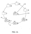
- FIG. 1a the architecture according to a first embodiment of the present invention is schematically explained, which provides a plurality of peripheral devices 11a, 11b, ..., 11n and a central device 111.
- the peripheral devices 11a, 11b, ... 11n are wireless devices, that is they have no wire connections, are supplied by batteries 13 and communicate by radio waves through antennas 19.
- the central device 111 is equipped with an antenna 119 for communicating with the peripheral devices 11a, 11b, ... 11n and is supplied by a battery 113.
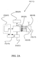
- peripheral devices 11a, 11b,...11n which, as anticipated above, are supplied by a battery 13, communicate from and to the outside by integrated transmitting 15 and receiving 17 radio units, connected to the antenna 19.
- peripheral devices 11a, 11b, ...11n are provided with means 21 for generating a local timing signal CLK loc by which the turn-on and the turn-off of said radio units 15, 17 are periodically controlled.
- Said peripheral devices are further provided with a processing unit or CPU 23, which is equipped with storage means 25, either integrated or external, and, optionally, with an I/O gate 27.
- a processing unit or CPU 23 which is equipped with storage means 25, either integrated or external, and, optionally, with an I/O gate 27.
- the central device 111 which has substantially the same structure as the peripheral devices, is supplied by a battery 113 and communicates from and to the outside by means of a transmitting 115 and receiving 117 radio unit, which are integrated and equipped with an antenna 119.
- the central device 111 is further provided with a processing unit or CPU 123, which is equipped with storage means 125, either integrated or external.
- peripheral devices 11a, 11b, ...11n the control of the transmitting 15 and receiving 17 unit and of the flow of data from and to the outside is committed to the CPU processing unit 23; moreover, the CPU processing unit 23 manages I/O peripheral devices, if any. In performing out these tasks, the CPU 23 utilises the information and the program steps stored in the storage unit 25.
- Said storage unit 25 contains also the operation information and parameters of the peripheral device, such as the time length of the "on” and “off” states of the radio units.
- the transmitting 15 and receiving 17 radio unit is controlled by the CPU 23 through the following control signals:
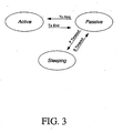
- the state of minimal consumption (“sleeping state”) in correspondence with the peripheral devices 11a, 11b, ... 11n is achieved by imposing the off state to the transmitting 15 and receiving 17 radio units.
- the peripheral device can neither transmit nor receive and the CPU 23 just performs the minimal functions of management of the I/O gates, if any.
- the peripheral device is in the sleeping state.
- the transition from the "sleeping state" to the “passive state” and “active state” is determined by the local timing signal CLK loc and/or by events internal or external to the peripheral device.
- the central device 111 since the central device 111 is supplied by batteries, it should alternate activity and inactivity phases of the radio unit, in order to reduce consumption to a minimum.
- S Timeout switches the machine state from the "sleeping state” to the "passive state", where the peripheral/central device is able to receive through the receiving radio unit 17;
- P Timeout switches the machine state to the "sleeping state", where both the transmitting 15 and receiving 17 units are turned off;
- Tx Req switches the machine state to the "active state” and coincides with the transmission requests due to either external events (variation on the I/O gates) or internal events (answers to received data or information produced at predetermined time);
- Tx End switches the machine state from the "active state” to the "passive state” and coincides with the end of the transmission.
- peripheral devices 11a, 11b,... 11n have also a "sync state", i.e. a time synchrony state where they synchronise with the central device or with a network timing device, if the latter is separated from the central device.
- sync state i.e. a time synchrony state where they synchronise with the central device or with a network timing device, if the latter is separated from the central device.
- peripheral devices When the peripheral devices are synchronised, they simultaneously switch to the "passive state". If any of the peripheral devices transmits in this time window, the others are able to receive.
- t indicates the media transfer time, intended as time overhead due to serialisation and protocol delays. Since “t” is known and/or can be calculated, it is possible to set up the length of the ON/OFF states of the peripheral and central devices (that is when they switch to the "passive state") in order to preserve synchronisation.
- the peripheral device which is out of synchrony switches to the "active state” and repeatedly sends the synchronisation request REQ_SYNC alternating "active states” and passive states” till the central device, which meanwhile has moved to the "passive state", is able to intercept said request.
- the central device once it has received the request REQ_SYNC, switches to the "active state" and sends the synchronisation string SYNC, which can be received by the peripheral device that has sent the request.
- the peripheral device that has received the synchronisation string SYNC is therefore able to synchronise its clock with the one of the central device. This is done by the CPU 23 aboard the peripheral device.
- the peripheral device On performing synchronisation with the time base of the central device, the peripheral device must consider the media transfer times "t" and the time “T” between the beginning of the "passive state” in the central device and the sending of the string SYNC from said device; the time “t” is calculated by the peripheral device on the basis of the delay of the answer received from the central device, while the time “T” is contained in the synchronisation string sent by the central device.
- the peripheral device which is now synchronised, can switch to the "active state” and transmit a data string DATA exactly in the time slot when the central device is in the "passive state” and, consequently, is able to receive said string.
- the time window during which the central device is in "passive state" and, consequently, is able to listen to the peripheral device is opened at regular intervals and has a length which is dynamically variable depending on the amount of received data.
- the central device Once the central device has received the data string, it switches to the "active state" and sends a confirmation string ACK, which is received by the peripheral device.
- the synchronisation procedure gets a special significance, for the system operation, since it allows for:
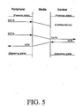
- the peripheral device which is in "active state”, sends a data string DATA that is received by the central device 111, which is in "passive state", with a delay depending upon the media and upon collision errors that may occur.
- the central device 111 once it has received the data string DATA, confirms reception by sending a string ACK and, once the peripheral device has received said string, it switches to the "sleeping state".
- the peripheral device If the peripheral device does not receive the string ACK in a predetermined time, it will recognise the state of non-synchrony with the central device and the CPU of the peripheral device will perform the synchronisation loop previously disclosed.
- the string ACK preferably contains also the information of synchronisation SYNC, so that the correct synchronisation of the peripheral device with the network time base 121, which is preferably integrated in the central device 111, is restored.
- the central device 111 which is in "active state”, sends a string DATA that is received by the peripheral device 11, which is in "passive state", with a delay depending upon the media and upon collision errors that may occur.
- the peripheral device 11 once it has received the string DATA, confirms reception by sending a string ACK and, once the central device has received said string, the central device and the peripheral one switch to the "sleeping state".
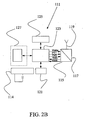
- the architecture according to a second embodiment of the present invention is schematically disclosed, said architecture involving a plurality of peripheral devices 11a, 11b,...11n supplied by battery, like in the first embodiment, but with a central device supplied by the public electric power network.
- the central device 111 does not provide for the turn-off of the receiving unit 117, which consequently is always available for receiving an information flow from the peripheral devices.
- a synchronisation session according to a further embodiment of the invention is disclosed, where the peripheral devices 11a, 11b,...11n, and the central device 111 are able to communicate at various frequencies, for example, f 1 , f 2 , ... f 10 , which vary according to a sequence fixed by an algorithm common to all the devices, both peripheral and central.
- f 1 , f 2 , ... f 10 which vary according to a sequence fixed by an algorithm common to all the devices, both peripheral and central.
- This measure known as frequency hopping, has the advantage of increasing the security of the radio transmissions inside the system on one part and of limiting the occupancy of any single frequency on the other part, according to the prescriptions of the certification rules, yet maintaining the possibility of transmitting for a much longer time.
- the synchronisation request at frequency rf is received by the central device 111, which periodically opens a listening window on the channel rf, preferably at the end of each passive state.
- the central device 111 transmits a synchronisation string SYNC, which, once received by the peripheral device, enables said device to synchronise with the central device. 111.
- the peripheral device can start the transmission of the data string DATA on one or more frequencies f 1 ,... f 10 , exactly during the opening of the listening window of the central device, when said device is in passive state.
- the central device 111 transmits a confirmation string ACK, upon reception of which the peripheral device switches to the "sleeping state".
- the synchronisation is carried out for the opening times of the reception and transmission windows, as well as for the sequence of the employed frequencies, so that the different devices, both peripheral and central, are able to talk to one another and to be listened to.
- the transmission protocol between the peripheral devices and the central one, and vice versa is of the CSMA (Carrier Sense Multiple Access) type, since possible collisions (simultaneous transmissions) may cause, in general, deterioration of the sent data.
- CSMA Carrier Sense Multiple Access
- Each device randomly shifts, within the limits of an established time window, the time when it switches from the "passive state” to the "active state", thus reducing the chances of collision and of possible successive collisions.
- the protocol involves operating strings (such as, for example, synchronisation requests, confirmation strings, network parameters transfer, etc.) and data string, by means of which the state information, events and application commands are transferred.
- strings such as, for example, synchronisation requests, confirmation strings, network parameters transfer, etc.
- the strings independently from their kind and function, contain the following fields:
- the fields (2) to (7) are preferably ciphered by means of a symmetric algorithm, for example by FEALnX algorithm (64 bit block-cipher), used in CBC (Cipher Block Chaining) mode, and/or with public key.
- FEALnX algorithm 64 bit block-cipher
- CBC Cipher Block Chaining
- the fields (1), (4), (5), (6) and (7) are necessary and sufficient, the fields (2), (3) and (8) depending on the application kind and/or to the implementation modes.
- the disclosed architecture can be specially applied in all those situations where there is a small traffic of data between the different devices (such as, for example, security systems or wireless environmental monitoring systems), but where, at the same time, bi-directional information flows and low consumption are required.
- devices such as, for example, security systems or wireless environmental monitoring systems
- the above disclosed architecture allows to reduce to a minimum the impact on consumption of the bi-directionality of the information flow, within a network of battery supplied equipment, working at - a set frequency, or, alternatively, to operate at several frequencies (in a limited set).
- peripheral devices for controlling, through the optional I/O gates previously disclosed, the periodical turn-on and turn-off of connected equipment, if any, thus achieving further energy saving.
- All the devices were supplied by lithium primary batteries and, thanks to the operation modes according to the invention, an endurance typically no lower than 2,5 years in standard conditions of use was estimated, against an endurance of few weeks in a conventional system.
Landscapes
- Engineering & Computer Science (AREA)
- Computer Networks & Wireless Communication (AREA)
- Physics & Mathematics (AREA)
- General Physics & Mathematics (AREA)
- Mobile Radio Communication Systems (AREA)
- Selective Calling Equipment (AREA)
- Communication Control (AREA)
Claims (22)
- Architektur zur zentralisierten Steuerung von entfernten elektrischen Peripheriegeräten, mit:- mindestens einem zentralen elektronisches Gerät (111), das eine Prozessoreinheit oder CPU (123), eine Übertragungseinheit (115), eine Empfangseinheit (117) und eine Stromversorgungseinheit (114) aufweist;- mindestens einem Gerät zur Erzeugung eines Netzwerkzeitsignals;- mindestens einem elektronischen Peripheriegerät (11a, 11b, ... 11n), das mit einer Prozessoreinheit oder CPU (23), einer Speichereinheit (25), einer Übertragungseinheit (15), einer Empfangseinheit (17), einem Gerät (21) zur Erzeugung eines lokalen Zeitsignals, einer Batterie (13) und einer Einrichtung zur periodischen Unterbrechung und Aktivierung der elektrischen Stromversorgung zur Übertragungs- und/oder Empfängereinheit ausgestattet ist,wobei das Peripheriegerät ( 11a, 11b, ... 11n) mittels eines Flusses von von der Zentraleinheit ausgehenden und von dem mindestens einen Peripheriegerät empfangenen Daten programmierbar ist und wobei das Peripheriegerät (11a, 11b, ... 11n) Einrichtungen aufweist, um diese Übertragungs- und Empfängereinheiten entsprechend den folgenden Maschinenzuständen zu schalten:- "Ruhezustand", wobei die Übertragungs- und Empfängereinheiten nicht mit Strom versorgt werden;- "Passivzustand", wobei die Empfangseinheit mit Strom versorgt und die Übertragungseinheit nicht mit Strom versorgt wird;- "Aktivzustand", wobei die Übertragungseinheit mit Strom versorgt wird, dadurch gekennzeichnet, dass das Peripheriegerät Einrichtungen zur Überlagerung des Peripheriegeräts mit einem "Sync Status" aufweist, wobei das Peripheriegerät mittels eines Synchronisierungsprotokolls mit der Netzwerkzeitvorrichtung synchronisiert wird, wenn das Peripheriegerät keine Bestätigung des korrekten Empfangs von an das Zentralgerät übermittelten Daten empfangen hat und das Ausbleiben der Bestätigung ein Anzeichen für das Fehlen der Synchronisation mit dem Zentralgerät ist.
- Architektur nach Anspruch 1,
wobei Einrichtungen vorgesehen sind, die einen Transfer eines Informationsflusses vom Zentralgerät (111) an das Peripheriegerät zulassen, wobei der Informationsfluss von der Empfängereinheit (17) im Peripheriegerät (11a, 11b, ...11n) empfangen werden kann und wobei diese Einrichtungen eine Synchronisierungsschleife der Einschalt- und Ausschaltlots der Übertragungs-/Empfängereinheiten (15, 17) des Peripheriegeräts bezüglich des Netzwerkzeitsignals einschließen, wie auch eine Datentransferschleife vom Zentralgerät (111) an das Peripheriegerät (11a, 11b, ... 11n). - Architektur nach Anspruch 2,
wobei das Zentralgerät (111) und/oder das Peripheriegerät in der Lage sind, periodisch vom "Ruhezustand" in den "Passivzustand" zu schalten, wobei die Frequenz dieser Umschaltung von einem lokalen Zeitsignal und der Zeitdauer des "Passivzustands" bestimmt wird, der vom lokalen Zeitsignal und dem Empfang von Datenflüssen der Empfängereinheit (17) festgelegt wird. - Architektur nach Anspruch 3,
wobei das Zentralgerät und/oder das Peripheriegerät in der Lage sind, periodisch vom "Passivzustand" in den "Aktivzustand" und umgekehrt zu schalten, wobei die Frequenz dieser Umschaltung durch das Auftreten eines im Zusammenhang mit dem Zentralgerät und/oder dem Peripheriegerät stehenden Ereignisses bestimmt wird, das übertragen werden soll. - Architektur nach einem der vorhergehenden Ansprüche,
wobei das Peripheriegerät ein Drahtlosgerät ist, und wobei die Übertragungseinheit und die Empfängereinheit jeweils eine Radioübertragungseinheit und eine Radioempfangseinheit sind. - Architektur nach einem der vorhergehenden Ansprüche,
wobei die Versorgungseinheit des Zentralgeräts und/oder des Peripheriegeräts eine Batterie enthalten. - Architektur nach Anspruch 2,
wobei die Versorgungseinheit des Zentralgeräts eine an ein öffentliches oder privates Stromversorgungsnetz angeschlossene Stromversorgung einschließt. - Architektur nach einem der vorhergehenden Ansprüche,
wobei die Einrichtung zur Erzeugung eines Netzwerkzeitsignals in das Zentralgerät integriert ist. - Architektur nach einem der vorhergehenden Ansprüche,
wobei das Peripheriegerät ein Sensor eines Diebstahlsicherungs- oder Feuermeldesystems ist und das Zentralgerät die Steuerungseinheit dieses Systems ist. - Architektur nach Anspruch 5,
wobei die Empfänger- und Übertragungsradioeinheiten dazu eingerichtet sind, miteinander auf verschiedenen Frequenzen zu kommunizieren, die zu einer Gruppe von vorbestimmten Frequenzen gehören, die gemäß einer Sequenz gewählt wurden, die vorbestimmt und allen Geräten gemein ist, wobei die Synchronisierungsschleife durch die Nutzung immer derselben Rückstellungsfrequenz aus dieser Gruppe von Frequenzen ausgeführt wird. - Verfahren für die zentralisierte Steuerung mittels mindestens eines elektronischen Zentralgeräts, das mit einer Prozessoreinheit oder CPU (123), einer Übertragungseinheit (115), einer Empfangseinheit (117), und einer Versorgungseinheit (114) versehen ist, und mittels eines Geräts (121) zur Erzeugung eines Netzwerkzeitsignals von Ereignissen, die im Zusammenhang mit entfernten elektronischen Peripheriegeräten auftreten, die mit einer Prozessoreinheit oder CPU (23), einer Speichereinheit (25), einer Übertragungseinheit (15), einer Empfangseinheit (17), einem Gerät (21) zur Erzeugung eines lokalen Zeitsignals, einer Batterie (13) und einer Einrichtung zur periodischen Unterbrechung und Aktivierung der elektrischen Stromversorgung zur Übertragungs- und/oder Empfängereinheit ausgestattet sind, wobei das Verfahren einen Schritt der Programmierung des mindestens einen Peripheriegeräts ( 11a, 11b, ... 11n) mittels eines Flusses von von der Zentraleinheit ausgehenden und vom Peripheriegerät empfangenen Daten,
wobei das Peripheriegerät (11a, 11b, ... 11n) gemäß folgender Maschinenzuständen betätigbar ist:- "Ruhezustand", wobei die Übertragungs- und Empfängereinheiten nicht mit Strom versorgt werden;- "Passivzustand", wobei die Empfangseinheit mit Strom versorgt und die Übertragungseinheit nicht mit Strom versorgt wird;- "Aktivzustand", wobei die Übertragungseinheit mit Strom versorgt wird, dadurch gekennzeichnet, dass das Verfahren folgende Schritte aufweist:Überlagerung des Peripheriegeräts mit einem "Sync Status", wobei das Peripheriegerät mittels eines Synchronisierungsprotokolls mit der Netzwerkzeitvorrichtung synchronisiert,und dass der "Sync Status" eingeführt wird, wenn das Peripheriegerät keine Bestätigung des korrekten Empfangs von den an das Zentralgerät übermittelten Daten empfangen hat und das Ausbleiben der Bestätigung ein Anzeichen für das Fehlen der Synchronisation mit dem Zentralgerät ist. - Verfahren nach Anspruch 11,
wobei das Synchronisierungsprotokoll folgende Schritte umfasst.- Umschalten des Peripheriegeräts auf den "Aktivzustand";- wiederholtes Senden einer Synchronisationsanfrage (REQ_SYNC) im Wechsel von "Aktivzuständen" und "Passivzuständen", bis das Zentralgerät diese Abfrage abfangen kann;- wenn es diese Anfrage (REQ_SYNC) empfangen hat, Umschalten der Zentralgeräts in den "Aktivzustand" und Absendung eines Synchronisationsstring (SYNC) an das Peripheriegerät, das die Anfrage gesandt hat;- Empfang des Synchronisationsstrings (SYNC) im Peripheriegerät;- Synchronisation der Uhr des Peripheriegeräts mit der des Zentralgeräts. - Verfahren nach Anspruch 12,
wobei das Zentralgerät, wenn es einen Datenstring empfangen hat, in den "Aktivzustand" schaltet und einen Bestätigungsstring ACK an das Peripheriegerät sendet, wobei der ACK-String auch die Synchronisationsinformation (SYNC) enthält, so dass die ordnungsgemäße Synchronisation des Peripheriegeräts mit der Netzwerkzeitbasis (121) aufrechterhalten wird. - Verfahren nach Anspruch 13,
wobei das Zeitfenster, während dessen das Zentralgerät sich im "Passivstatus" befindet und konsequenterweise das Peripheriegerät anhören kann, in regelmäßigen Abständen geöffnet wird und eine Länge aufweist, die dynamisch in Abhängigkeit von der empfangenen Datenmenge variabel ist. - Verfahren nach Anspruch 11,
wobei das Peripheriegerät mittels einer ersten Synchronisationsphase der Aufschalt- und Abschalteinschübe der Radioeinheiten des Peripheriegeräts mit dem Netzwerkzeitsignal und einer zweiten Phase, während der die Daten vom Zentralgerät an das Peripheriegerät gesendet werden, programmiert wird. - Verfahren nach Anspruch 15,
wobei die Synchronisationsphase die Sendung einer Synchronisationsanfrage (REQ_SYNC) durch das nicht synchronisierte Peripheriegerät aufweist und diese Anfrage wiederholt wird bis zum Empfang durch das Peripheriegerät einer von der Netzwerkzeitvorrichtung emittierten Antwort (SYNC). - Verfahren nach Anspruch 15,
wobei die Synchronisationsphase die Sendung einer Synchronisationsanfrage (REQ_SYNC) durch das nicht synchronisierte Peripheriegerät beinhaltet und diese Anfrage immer wiederholt wird auf derselben Rückstellfrequenz, die aus einer Gruppe von Frequenzen ausgewählt wurde, auf der die Peripheriegeräte und die Zentraleinheit zur Übertragung und zum Empfang von Daten arbeiten. - Verfahren nach Anspruch 11,
wobei der Datenfluss (DATA) zur Programmierung des Peripheriegeräts von der Zentraleinheit übertragen wird, wenn das Peripheriegerät sich im "Passivstatus" befindet und das Peripheriegerät am Ende des Empfangs des Datenflusses in den "Aktivstatus" wechselt, um an das Zentralgerät einen Bestätigungsstring (ACK) zu senden. - Verfahren nach einem der Ansprüche 11 bis 17,
wobei das Übertragungsprotokoll von den Peripheriegeräten an das Zentralgerät und umgekehrt vom Typ CSMA, Carrier Sense Multiple Access, ist und mindestens ein "Header"-Feld, das die Information über die Struktur des Strings selbst enthält, ein Feld, das die Adressen der Quelle und des Empfängers enthält, ein Feld, das die Stringlänge enthält, ein Feld, das die Daten enthält sowie ein Kontrollfeld aufweist. - Verfahren nach Anspruch 19,
wobei das Übertragungsprotokoll wenigstens ein Hilfskontrollfeld, ein Variantenfeld und ein Autokorrekturfeld aufweist. - Verfahren nach Anspruch 20,
wobei das Autokorrekturfeld nach dem Reed-Solomon Code codiert ist. - Verfahren nach einem der Ansprüche 19 bis 21,
wobei mindestens eines der Felder mittels eines symmetrischen Algorithmus verschlüsselt ist, zum Beispiel eines FEALnX Algorithmus, 64 bit Blockverschlüsselung, die im Blockchiffre-Modus verwendet wird und/oder mit einem öffentlichem Schlüssel.
Applications Claiming Priority (3)
| Application Number | Priority Date | Filing Date | Title |
|---|---|---|---|
| IT000692A ITTO20020692A1 (it) | 2002-08-02 | 2002-08-02 | Architettura e metodo per il controllo centralizzato |
| ITTO20020692 | 2002-08-02 | ||
| PCT/IB2003/003413 WO2004015647A2 (en) | 2002-08-02 | 2003-07-31 | Architecture and method for the centralised control of remote peripheral electronic devices |
Publications (2)
| Publication Number | Publication Date |
|---|---|
| EP1525568A2 EP1525568A2 (de) | 2005-04-27 |
| EP1525568B1 true EP1525568B1 (de) | 2010-09-08 |
Family
ID=11459555
Family Applications (1)
| Application Number | Title | Priority Date | Filing Date |
|---|---|---|---|
| EP03784377A Expired - Lifetime EP1525568B1 (de) | 2002-08-02 | 2003-07-31 | Architektur und verfahren zur zentralisierten steuerung von entfernten elektrischen peripheriegeräten |
Country Status (11)
| Country | Link |
|---|---|
| US (1) | US7415544B2 (de) |
| EP (1) | EP1525568B1 (de) |
| JP (1) | JP2005535251A (de) |
| AT (1) | ATE480845T1 (de) |
| AU (1) | AU2003249457B2 (de) |
| CA (1) | CA2493021C (de) |
| DE (1) | DE60334104D1 (de) |
| IL (1) | IL166353A0 (de) |
| IT (1) | ITTO20020692A1 (de) |
| NZ (1) | NZ538152A (de) |
| WO (1) | WO2004015647A2 (de) |
Families Citing this family (9)
| Publication number | Priority date | Publication date | Assignee | Title |
|---|---|---|---|---|
| WO2005008386A2 (en) * | 2003-07-07 | 2005-01-27 | Mformation Technologies, Inc. | System and method for over the air (ota) wireless device and network management |
| US7174268B2 (en) | 2004-08-18 | 2007-02-06 | Ube Industries Ltd. | Wireless measuring device |
| US8312142B2 (en) * | 2005-02-28 | 2012-11-13 | Motorola Mobility Llc | Discontinuous transmission/reception in a communications system |
| JP5000652B2 (ja) * | 2005-07-28 | 2012-08-15 | エムフォメーション・テクノロジーズ・インコーポレイテッド | ワイヤレス装置のサービス品質管理のためのシステムおよび方法 |
| JP5124455B2 (ja) * | 2005-07-28 | 2013-01-23 | エムフォメーション・テクノロジーズ・インコーポレイテッド | 装置の機能性を遠隔的に制御するためのシステムおよび方法 |
| US7961088B2 (en) * | 2006-08-18 | 2011-06-14 | Cattail Technologies, Inc. | Asset monitoring system and portable security system therefor |
| WO2015107689A1 (ja) * | 2014-01-20 | 2015-07-23 | 富士通株式会社 | 通信ノード、システム、および同期方法 |
| CN104917619A (zh) * | 2014-03-14 | 2015-09-16 | 海尔集团公司 | 一种唤醒控制方法及终端 |
| LU100947B1 (en) * | 2018-09-27 | 2020-03-27 | Nanopower As | Device connection system and method of operation |
Family Cites Families (6)
| Publication number | Priority date | Publication date | Assignee | Title |
|---|---|---|---|---|
| GB2271691A (en) * | 1992-09-21 | 1994-04-20 | Oconnor P J | Synchronisation of a radio telemetry system |
| US5627882A (en) * | 1993-06-02 | 1997-05-06 | U.S. Philips Corporation | Enhanced power saving method for hand-held communications system and a hand-held communications system therefor |
| US5854994A (en) * | 1996-08-23 | 1998-12-29 | Csi Technology, Inc. | Vibration monitor and transmission system |
| DE19947344A1 (de) | 1999-10-01 | 2001-04-12 | Abb Research Ltd | Sensor mit drahtloser Datenübertragung mit geringer Leistungsaufnahme |
| JP4879436B2 (ja) * | 2000-02-23 | 2012-02-22 | マイクロソフト コーポレーション | ワイヤレス・リンクを有する通信経路を通じてのサービス品質 |
| AU2003213063A1 (en) * | 2002-02-19 | 2003-09-09 | Pda Verticals Corp. | Multiple wireless device synchronization server |
-
2002
- 2002-08-02 IT IT000692A patent/ITTO20020692A1/it unknown
-
2003
- 2003-07-31 AT AT03784377T patent/ATE480845T1/de not_active IP Right Cessation
- 2003-07-31 WO PCT/IB2003/003413 patent/WO2004015647A2/en not_active Ceased
- 2003-07-31 EP EP03784377A patent/EP1525568B1/de not_active Expired - Lifetime
- 2003-07-31 CA CA002493021A patent/CA2493021C/en not_active Expired - Fee Related
- 2003-07-31 NZ NZ538152A patent/NZ538152A/en not_active IP Right Cessation
- 2003-07-31 US US10/522,196 patent/US7415544B2/en not_active Expired - Fee Related
- 2003-07-31 JP JP2004527189A patent/JP2005535251A/ja active Pending
- 2003-07-31 DE DE60334104T patent/DE60334104D1/de not_active Expired - Lifetime
- 2003-07-31 AU AU2003249457A patent/AU2003249457B2/en not_active Ceased
-
2005
- 2005-01-18 IL IL16635305A patent/IL166353A0/xx active IP Right Grant
Also Published As
| Publication number | Publication date |
|---|---|
| WO2004015647A2 (en) | 2004-02-19 |
| IL166353A0 (en) | 2006-01-16 |
| ITTO20020692A1 (it) | 2004-02-03 |
| EP1525568A2 (de) | 2005-04-27 |
| CA2493021C (en) | 2009-09-22 |
| DE60334104D1 (de) | 2010-10-21 |
| CA2493021A1 (en) | 2004-02-19 |
| US7415544B2 (en) | 2008-08-19 |
| US20050268118A1 (en) | 2005-12-01 |
| AU2003249457A1 (en) | 2004-02-25 |
| ITTO20020692A0 (it) | 2002-08-02 |
| JP2005535251A (ja) | 2005-11-17 |
| NZ538152A (en) | 2006-08-31 |
| WO2004015647A3 (en) | 2004-06-03 |
| AU2003249457B2 (en) | 2009-04-09 |
| ATE480845T1 (de) | 2010-09-15 |
Similar Documents
| Publication | Publication Date | Title |
|---|---|---|
| EP1665738B1 (de) | Synchronisierungs-hf-system | |
| US5625882A (en) | Power management technique for determining a device mode of operation | |
| US7289578B2 (en) | Wireless local area network apparatus | |
| KR0138973B1 (ko) | 클럭 주파수를 제어하여 전자 회로의 전력 소모를 최소화시키는 방법 및 장치 | |
| KR100626675B1 (ko) | 무선 통신기기 및 그 제어방법 | |
| WO2004110099A3 (en) | A hearing aid wireless network | |
| US20120033584A1 (en) | Energy efficient transmission in a network | |
| CA2345783A1 (en) | Access technique of channel hopping communications system | |
| JP2008503153A (ja) | 複数ノードとマスターとの間の通信を提供する方法とシステム | |
| EP1525568B1 (de) | Architektur und verfahren zur zentralisierten steuerung von entfernten elektrischen peripheriegeräten | |
| KR20000069653A (ko) | 채널 호핑 통신 시스템의 액세스 기술 | |
| JP3777155B2 (ja) | 接続率の向上が可能な無線通信機器及びその方法 | |
| JPH02256331A (ja) | 無線通信システム | |
| EP1289193B1 (de) | Drahtloses Kommunikationsverfahren zur Vermeidung von Kommunikationsinterferenz und -abbruch in drahtloser Punkt-zu-Mehrpunkt-Kommunikation | |
| AU2003263164A1 (en) | Method for controlling a data transmission in a radiocommunication system with a hierarchical network architecture | |
| US20050265501A1 (en) | Resynchronizing timing sync pulses in a synchronizing RF system | |
| JP2005535251A5 (de) | ||
| JP3180449B2 (ja) | 送受信装置 | |
| JP4977943B2 (ja) | 通信システム | |
| US7260359B2 (en) | Method for transmission of data between a master station and a slave station, and a data transmission system | |
| JP2009016974A (ja) | 無線送信装置および無線通信システム | |
| KR101125433B1 (ko) | 무선 랜 중계 장치 및 방법 | |
| JPH11243581A (ja) | ローカル無線通信システムの送受信の動作を制御する方法 | |
| RU2686034C1 (ru) | Способ беспроводной связи охранной сигнализации | |
| JPH11127165A (ja) | 無線lanシステムとバッテリセーブ方法 |
Legal Events
| Date | Code | Title | Description |
|---|---|---|---|
| PUAI | Public reference made under article 153(3) epc to a published international application that has entered the european phase |
Free format text: ORIGINAL CODE: 0009012 |
|
| 17P | Request for examination filed |
Effective date: 20050203 |
|
| AK | Designated contracting states |
Kind code of ref document: A2 Designated state(s): AT BE BG CH CY CZ DE DK EE ES FI FR GB GR HU IE IT LI LU MC NL PT RO SE SI SK TR |
|
| AX | Request for extension of the european patent |
Extension state: AL LT LV MK |
|
| DAX | Request for extension of the european patent (deleted) | ||
| 17Q | First examination report despatched |
Effective date: 20071029 |
|
| GRAP | Despatch of communication of intention to grant a patent |
Free format text: ORIGINAL CODE: EPIDOSNIGR1 |
|
| GRAS | Grant fee paid |
Free format text: ORIGINAL CODE: EPIDOSNIGR3 |
|
| GRAA | (expected) grant |
Free format text: ORIGINAL CODE: 0009210 |
|
| AK | Designated contracting states |
Kind code of ref document: B1 Designated state(s): AT BE BG CH CY CZ DE DK EE ES FI FR GB GR HU IE IT LI LU MC NL PT RO SE SI SK TR |
|
| REG | Reference to a national code |
Ref country code: GB Ref legal event code: FG4D |
|
| REG | Reference to a national code |
Ref country code: CH Ref legal event code: EP |
|
| REG | Reference to a national code |
Ref country code: IE Ref legal event code: FG4D |
|
| REF | Corresponds to: |
Ref document number: 60334104 Country of ref document: DE Date of ref document: 20101021 Kind code of ref document: P |
|
| REG | Reference to a national code |
Ref country code: CH Ref legal event code: NV Representative=s name: KEMIA SA |
|
| REG | Reference to a national code |
Ref country code: NL Ref legal event code: VDEP Effective date: 20100908 |
|
| PG25 | Lapsed in a contracting state [announced via postgrant information from national office to epo] |
Ref country code: FI Free format text: LAPSE BECAUSE OF FAILURE TO SUBMIT A TRANSLATION OF THE DESCRIPTION OR TO PAY THE FEE WITHIN THE PRESCRIBED TIME-LIMIT Effective date: 20100908 Ref country code: AT Free format text: LAPSE BECAUSE OF FAILURE TO SUBMIT A TRANSLATION OF THE DESCRIPTION OR TO PAY THE FEE WITHIN THE PRESCRIBED TIME-LIMIT Effective date: 20100908 |
|
| PG25 | Lapsed in a contracting state [announced via postgrant information from national office to epo] |
Ref country code: CY Free format text: LAPSE BECAUSE OF FAILURE TO SUBMIT A TRANSLATION OF THE DESCRIPTION OR TO PAY THE FEE WITHIN THE PRESCRIBED TIME-LIMIT Effective date: 20100908 Ref country code: SI Free format text: LAPSE BECAUSE OF FAILURE TO SUBMIT A TRANSLATION OF THE DESCRIPTION OR TO PAY THE FEE WITHIN THE PRESCRIBED TIME-LIMIT Effective date: 20100908 |
|
| PG25 | Lapsed in a contracting state [announced via postgrant information from national office to epo] |
Ref country code: GR Free format text: LAPSE BECAUSE OF FAILURE TO SUBMIT A TRANSLATION OF THE DESCRIPTION OR TO PAY THE FEE WITHIN THE PRESCRIBED TIME-LIMIT Effective date: 20101209 Ref country code: SE Free format text: LAPSE BECAUSE OF FAILURE TO SUBMIT A TRANSLATION OF THE DESCRIPTION OR TO PAY THE FEE WITHIN THE PRESCRIBED TIME-LIMIT Effective date: 20100908 Ref country code: NL Free format text: LAPSE BECAUSE OF FAILURE TO SUBMIT A TRANSLATION OF THE DESCRIPTION OR TO PAY THE FEE WITHIN THE PRESCRIBED TIME-LIMIT Effective date: 20100908 |
|
| PG25 | Lapsed in a contracting state [announced via postgrant information from national office to epo] |
Ref country code: RO Free format text: LAPSE BECAUSE OF FAILURE TO SUBMIT A TRANSLATION OF THE DESCRIPTION OR TO PAY THE FEE WITHIN THE PRESCRIBED TIME-LIMIT Effective date: 20100908 Ref country code: SK Free format text: LAPSE BECAUSE OF FAILURE TO SUBMIT A TRANSLATION OF THE DESCRIPTION OR TO PAY THE FEE WITHIN THE PRESCRIBED TIME-LIMIT Effective date: 20100908 Ref country code: CZ Free format text: LAPSE BECAUSE OF FAILURE TO SUBMIT A TRANSLATION OF THE DESCRIPTION OR TO PAY THE FEE WITHIN THE PRESCRIBED TIME-LIMIT Effective date: 20100908 Ref country code: EE Free format text: LAPSE BECAUSE OF FAILURE TO SUBMIT A TRANSLATION OF THE DESCRIPTION OR TO PAY THE FEE WITHIN THE PRESCRIBED TIME-LIMIT Effective date: 20100908 Ref country code: PT Free format text: LAPSE BECAUSE OF FAILURE TO SUBMIT A TRANSLATION OF THE DESCRIPTION OR TO PAY THE FEE WITHIN THE PRESCRIBED TIME-LIMIT Effective date: 20110110 |
|
| PG25 | Lapsed in a contracting state [announced via postgrant information from national office to epo] |
Ref country code: ES Free format text: LAPSE BECAUSE OF FAILURE TO SUBMIT A TRANSLATION OF THE DESCRIPTION OR TO PAY THE FEE WITHIN THE PRESCRIBED TIME-LIMIT Effective date: 20101219 Ref country code: BE Free format text: LAPSE BECAUSE OF FAILURE TO SUBMIT A TRANSLATION OF THE DESCRIPTION OR TO PAY THE FEE WITHIN THE PRESCRIBED TIME-LIMIT Effective date: 20100908 |
|
| PLBE | No opposition filed within time limit |
Free format text: ORIGINAL CODE: 0009261 |
|
| STAA | Information on the status of an ep patent application or granted ep patent |
Free format text: STATUS: NO OPPOSITION FILED WITHIN TIME LIMIT |
|
| 26N | No opposition filed |
Effective date: 20110609 |
|
| PG25 | Lapsed in a contracting state [announced via postgrant information from national office to epo] |
Ref country code: DK Free format text: LAPSE BECAUSE OF FAILURE TO SUBMIT A TRANSLATION OF THE DESCRIPTION OR TO PAY THE FEE WITHIN THE PRESCRIBED TIME-LIMIT Effective date: 20100908 |
|
| REG | Reference to a national code |
Ref country code: DE Ref legal event code: R097 Ref document number: 60334104 Country of ref document: DE Effective date: 20110609 |
|
| PG25 | Lapsed in a contracting state [announced via postgrant information from national office to epo] |
Ref country code: MC Free format text: LAPSE BECAUSE OF NON-PAYMENT OF DUE FEES Effective date: 20110731 |
|
| REG | Reference to a national code |
Ref country code: IE Ref legal event code: MM4A |
|
| PG25 | Lapsed in a contracting state [announced via postgrant information from national office to epo] |
Ref country code: IE Free format text: LAPSE BECAUSE OF NON-PAYMENT OF DUE FEES Effective date: 20110731 |
|
| PG25 | Lapsed in a contracting state [announced via postgrant information from national office to epo] |
Ref country code: LU Free format text: LAPSE BECAUSE OF NON-PAYMENT OF DUE FEES Effective date: 20110731 |
|
| PG25 | Lapsed in a contracting state [announced via postgrant information from national office to epo] |
Ref country code: TR Free format text: LAPSE BECAUSE OF FAILURE TO SUBMIT A TRANSLATION OF THE DESCRIPTION OR TO PAY THE FEE WITHIN THE PRESCRIBED TIME-LIMIT Effective date: 20100908 Ref country code: BG Free format text: LAPSE BECAUSE OF FAILURE TO SUBMIT A TRANSLATION OF THE DESCRIPTION OR TO PAY THE FEE WITHIN THE PRESCRIBED TIME-LIMIT Effective date: 20101208 |
|
| PG25 | Lapsed in a contracting state [announced via postgrant information from national office to epo] |
Ref country code: HU Free format text: LAPSE BECAUSE OF FAILURE TO SUBMIT A TRANSLATION OF THE DESCRIPTION OR TO PAY THE FEE WITHIN THE PRESCRIBED TIME-LIMIT Effective date: 20100908 |
|
| REG | Reference to a national code |
Ref country code: FR Ref legal event code: PLFP Year of fee payment: 13 |
|
| REG | Reference to a national code |
Ref country code: FR Ref legal event code: PLFP Year of fee payment: 14 |
|
| REG | Reference to a national code |
Ref country code: FR Ref legal event code: PLFP Year of fee payment: 15 |
|
| REG | Reference to a national code |
Ref country code: FR Ref legal event code: PLFP Year of fee payment: 16 |
|
| PGFP | Annual fee paid to national office [announced via postgrant information from national office to epo] |
Ref country code: GB Payment date: 20190729 Year of fee payment: 17 |
|
| PGFP | Annual fee paid to national office [announced via postgrant information from national office to epo] |
Ref country code: CH Payment date: 20191028 Year of fee payment: 17 |
|
| PGFP | Annual fee paid to national office [announced via postgrant information from national office to epo] |
Ref country code: DE Payment date: 20200928 Year of fee payment: 18 Ref country code: FR Payment date: 20200729 Year of fee payment: 18 |
|
| REG | Reference to a national code |
Ref country code: CH Ref legal event code: PL |
|
| GBPC | Gb: european patent ceased through non-payment of renewal fee |
Effective date: 20200731 |
|
| PG25 | Lapsed in a contracting state [announced via postgrant information from national office to epo] |
Ref country code: GB Free format text: LAPSE BECAUSE OF NON-PAYMENT OF DUE FEES Effective date: 20200731 Ref country code: LI Free format text: LAPSE BECAUSE OF NON-PAYMENT OF DUE FEES Effective date: 20200731 Ref country code: CH Free format text: LAPSE BECAUSE OF NON-PAYMENT OF DUE FEES Effective date: 20200731 |
|
| REG | Reference to a national code |
Ref country code: DE Ref legal event code: R119 Ref document number: 60334104 Country of ref document: DE |
|
| PG25 | Lapsed in a contracting state [announced via postgrant information from national office to epo] |
Ref country code: DE Free format text: LAPSE BECAUSE OF NON-PAYMENT OF DUE FEES Effective date: 20220201 |
|
| PG25 | Lapsed in a contracting state [announced via postgrant information from national office to epo] |
Ref country code: FR Free format text: LAPSE BECAUSE OF NON-PAYMENT OF DUE FEES Effective date: 20210731 |
|
| PGFP | Annual fee paid to national office [announced via postgrant information from national office to epo] |
Ref country code: IT Payment date: 20220719 Year of fee payment: 20 |