BACKGROUND OF THE INVENTION
1) Field of the Invention
The present invention relates to an optical pickup device and an
optical recording medium reproducing device.
2) Description of the Related Art
Conventionally, there is known an optical pickup device that
reads information recorded in an optical recording medium such as a
compact disc (CD) or a digital video disc (DVD) by a laser beam. The
optical pickup device at least includes a light source that outputs a
laser beam, an optical system that focuses laser beams output from the
light source on a recording layer in the optical recording medium, and a
light receiving unit that receives a return light from the recording layer.
The optical pickup device uses the mechanism to irradiate a laser beam
on the optical recording medium and to read information recorded in
the recording layer based on an intensity of the return light acquired in
the light receiving unit, or the like.
In the optical pickup device, a laser beam output from the light
source is required to be focused on a spot having a predetermined
diameter in the recording layer to avoid occurrence of reading error or
the like as much as possible. Particularly, in recent years, a recording
density is remarkably improved along with a larger capacity of the
optical recording medium, thus a smaller spot diameter is required to
be realized. Therefore, there has been proposed an optical pickup
device that mounts a phase correcting unit for avoiding occurrence of a
wavefront aberration which causes enlargement of a spot diameter as
well as a design feature of the optical system.
The phase correcting unit is positioned between the light source
and the optical recording medium, and is formed to include a liquid
crystal panel, for example. A liquid crystal material contained in the
liquid crystal panel has a structure where an index of refraction
changes according to an applied voltage so that an appropriate applied
voltage is selected to compensate for a phase difference in a laser
beam that causes a wavefront aberration and to restrict occurrence of
the wavefront aberration to a permissible degree (see Japanese Patent
Application Laid-Open No. H9-128785).
However, since there are many factors that may cause the
wavefront aberration, in the optical pickup device having a mechanism
that uses a plurality of laser sources to read information recorded in a
plurality of kinds of recording mediums, it is difficult to compensate for
a phase difference in a laser beam and to restrict occurrence of the
wavefront aberration only by applying an appropriate applied voltage to
a liquid crystal panel. Particularly, in using Blue ray Disk (BD) and
DVD, the wavefront aberration easily influences reading of these optical
recording mediums.
SUMMARY OF THE INVENTION
It is an object of the present invention to solve at least the
problems in the conventional technology.
An optical pickup device according to an aspect of the present
invention includes a light source that outputs a light; an optical system
through which the light is passed to thereby form a light spot on a
surface of an optical recording medium; an optical system aberration
correcting unit that corrects an optical system wavefront aberration that
occurs while the light passes through the optical system so that the
light that illuminates the surface is less in the optical system wavefront
aberration; a medium aberration correcting unit that corrects a medium
wavefront aberration that occurs due to an angle between the light that
illuminates the surface and the surface so that the light that illuminates
the surface is less in the medium wavefront aberration; and a light
receiving unit that receives a light that is reflected the surface.
An optical recording medium reproducing device according to
another aspect of the present invention performs light irradiating on an
irradiated surface of an optical recording medium and reproduces
information recorded in the optical recording medium based on a return
light of the irradiated light. The optical recording medium reproducing
device includes a plurality of light sources that output an irradiating
light; an optical system that forms a spot on the irradiated surface
based on the irradiating light output from the light sources; an optical
system aberration correcting unit that corrects an optical system
wavefront aberration that occurs while the irradiating light passes
through the optical system; a medium aberration correcting unit that
corrects a medium wavefront aberration that occurs based on an angle
between the irradiated surface and the irradiating light in the irradiated
surface; a light receiving unit that receives a return light whose
wavefront aberration is corrected by the optical system aberration
correcting unit and the medium aberration correcting unit; and a
demodulating unit that demodulates information recorded in the optical
recording medium based on a return light received in the light receiving
unit.
The other objects, features, and advantages of the present
invention are specifically set forth in or will become apparent from the
following detailed description of the invention when read in conjunction
with the accompanying drawings.
BRIEF DESCRIPTION OF THE DRAWINGS
Fig. 1 is a schematic diagram of an optical recording medium
reproducing device according to a first embodiment of the present
invention;
Fig. 2A is a side view of a liquid crystal panel;
Fig. 2B is a schematic diagram for explaining the operation of
the liquid crystal panel shown in Fig. 2;
Fig. 2C is a graph of a voltage applied to a transparent
electrode provided in the liquid crystal panel and a phase difference
which occurs in a transmitted light;
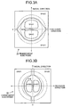
Fig. 3A is a schematic diagram of an electrode pattern of a
transparent electrode used for correcting a medium wavefront
aberration;
Fig. 3B is a schematic diagram of an electrode pattern of a
transparent electrode used for correcting an optical system wavefront
aberration;
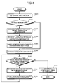
Fig. 4 is a flowchart for explaining a process procedure
performed by a control mechanism shown in Fig. 1;
Fig. 5 is a graph of an inclination of an optical recording medium
and a variance of a wavefront aberration in using a DVD;
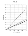
Fig. 6 is a graph of an inclination of the optical recording
medium and a variance of the wavefront aberration in using a BD;
Fig. 7A is a schematic diagram of an electrode pattern of a
transparent electrode used for correcting the medium wavefront
aberration according to a first variant of the first embodiment;
Fig. 7B is a graph of an inclination of the optical recording
medium and a variance of the wavefront aberration in using a BD
according to the first variant;
Fig. 8 is a graph of a change in the variance of the wavefront
aberration relative to a displacement in the positional relationship
between an objective lens and the liquid crystal panel in using a DVD
according to the first variant;
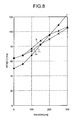
Fig. 9 is a graph of a change in the variance of the wavefront
aberration relative to a displacement in the positional relationship
between the objective lens and the liquid crystal panel in using a BD
according to the first variant.
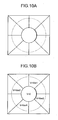
Fig. 10A is a schematic diagram of an electrode pattern of a
transparent electrode used for correcting the optical system wavefront
aberration according to a second variant of the first embodiment;
Fig. 10B is a schematic diagram of a voltage applied to each
pattern when correcting the optical system wavefront aberration
according to the second variant;
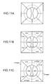
Fig. 11A is a schematic diagram of an electrode pattern of a
transparent electrode used for correcting the optical system wavefront
aberration according to a third variant of the first embodiment;
Fig. 11 B is a schematic diagram of a voltage applied to each
pattern when a comatic aberration occurs as the optical system
wavefront aberration according to the third variant;
Fig. 11C is a schematic diagram of a voltage applied to each
pattern when astigmatism occurs as the optical system wavefront
aberration according to the third variant;
Fig. 12A is a schematic diagram of an electrode pattern of a
transparent electrode used for correcting the optical system wavefront
aberration according to a fourth variant of the first embodiment;
Fig. 12B is a schematic diagram of a voltage applied to each
pattern when a comatic aberration occurs as the optical system
wavefront aberration according to the fourth variant;
Fig. 12C is a schematic diagram of a voltage applied to each
pattern when a spherical aberration occurs as the optical system
wavefront aberration according to the fourth variant;
Fig. 13A is a schematic diagram of an electrode pattern of a
transparent electrode used for correcting the optical system wavefront
aberration according to a fifth variant of the first embodiment;
Fig. 13B is a schematic diagram of a voltage applied to each
pattern when a comatic aberration occurs as the optical system
wavefront aberration according to the fifth variant;
Fig. 13C is a schematic diagram of a voltage applied to each
pattern when astigmatism occurs as the optical system wavefront
aberration according to the fifth variant;
Fig. 13D is a schematic diagram of a voltage applied to each
pattern when a spherical aberration occurs as the optical system
wavefront aberration according to the fifth variant;
Fig. 14 is a schematic diagram of an optical recording medium
reproducing device according to a second embodiment of the present
invention;
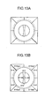
Fig. 15A is a schematic diagram of an electrode pattern of a
transparent electrode used for correcting the medium wavefront
aberration according to a variant of the second embodiment; and
Fig. 15B is a schematic diagram of an electrode pattern of a
transparent electrode used for correcting the optical system wavefront
aberration according to the variant of the second embodiment.
DETAILED DESCRIPTION
Exemplary embodiments of an optical pickup device and an
optical recording medium reproducing device according to the present
invention will be explained below in detail while referring to the
accompanying drawings. It should be noted that the drawings are
schematic and that a relationship between thickness and width in each
portion, ratios of thicknesses in respective portions, and the like are
different from actual ones, and it is natural that portions with mutually
different dimensional relationships or ratios are included in the
respective drawings. The following embodiments where a DVD and a
BD are used as an optical recording medium will be explained, but an
optical recording medium to be used may be any information recording
medium from which recorded information can be optically read, such as
a CD or AOD (Advanced Optical Disc).
Fig. 1 is a schematic diagram of an optical recording medium
reproducing device according to a first embodiment of the present
invention. This optical recording medium reproducing device includes
an optical pickup mechanism 1 that has a function of irradiating a laser
beam on the optical recording medium 14 and receiving a return light
from the optical recording medium 14, and a control mechanism 2 that
has a function of controlling a driving state of the optical pickup
mechanism 1 and reproducing information based on the return light
acquired in the optical pickup mechanism 1.
The optical pickup mechanism 1 includes laser sources 3 and 4
that are used according to the kind of the optical recording medium 14,
a dichroic prism 5 that is sequentially positioned on optical paths of the
laser beams emitted from the laser sources 3 and 4, a polarizing beam
splitter 6, a collimator 7, a raising prism 8, a liquid crystal panel 9 that
functions as an aberration correcting unit, a wavelength plate 10, and
an objective lens 11. The optical pickup mechanism 1 includes a
detector 12 that receives a return light split in the polarizing beam
splitter 6, and a focus adjusting mechanism 13 that has a function such
as focus adjustment of the objective lens 11. In the first embodiment,
constituents of the optical pickup mechanism 1 other than the laser
sources 3, 4, and the detector 12 may be referred to as an optical
system. It is noted that the optical system may employ any structure
having a function of forming a spot on an irradiated surface based on a
light output from the light source, and is not limited to the structure
shown in Fig. 1.
The laser sources 3 and 4 each have a function of outputting a
laser beam with a wavelength optimized for the optical recording
medium 14 to be read. In the first embodiment, a DVD or BD is used
as one example of the optical recording medium 14 to be read, the
laser source 3 outputs a blue laser beam corresponding to the BD, and
the laser source 4 outputs a red laser beam corresponding to the DVD.
The dichroic prism 5 reflects a laser beam output from the laser
source 3 to change the traveling direction by 90 degrees, while
transmits a laser beam output from the laser source 4, so that the
respective laser beams are incident in the polarizing beam splitter 6 or
the like. Specifically, the dichroic prism 5 has light transmission
characteristics corresponding to the wavelength of the incident light to
reflect substantially 100% of the blue laser beam output from the laser
source 3, while having characteristics where a reflectivity of the red
laser beam output from the laser source 4 is substantially 0%.
The polarizing beam splitter 6 transmits the laser beams output
from the laser sources 3 and 4, while reflecting and introducing a return
light from the optical recording medium 14 to the detector 12.
Specifically, the polarizing beam splitter 6 has light transmission
characteristics corresponding to the polarization direction of the
incident light, and has characteristics of transmitting substantially 100%
of the laser beam with a predetermined polarization direction output
from the laser source 3 or 4 and reflecting substantially 100% of a
return light with a polarization direction that is rotated by a
predetermined angle relative to the polarization direction. The dichroic
prism 5 and the polarizing beam splitter 6 are employed in the first
embodiment in terms of suppression of optical loss, but a structure of a
half mirror or the like may be simply employed.
The collimator 7 converts a laser beam output from the laser
source 3 or 4 into a parallel light flux. Thus the laser beam that
passed through the collimator 7 travels as a parallel beam until it is
refocused by the objective lens 11.
The raising prism 8 reflects the laser beam that passed through
the collimator 7 and changes the traveling direction of the laser beam
into the direction orthogonal to the surface of the optical recording
medium 14. The optical system can be constituted so that the laser
beam travels in the direction orthogonal to the surface of the optical
recording medium 14 when it passes through the collimator 7, but in the
first embodiment the optical system can be constituted so that the laser
beam travels halfway in the direction parallel to the surface of the
optical recording medium 14 and then changes the traveling direction
by the raising prism 8 to avoid enlargement of the entire device.
The liquid crystal panel 9 reduces, and more preferably
eliminates a phase difference of a passing laser beam, and restricts the
degree of a wavefront aberration, which occurs when the laser beam
forms a spot on the optical recording medium 14 within a permissible
range. A specific structure of the liquid crystal panel 9 and operations
thereof will be explained below in detail.
The wavelength plate 10 converts a laser beam incident in a
linearly polarized state into a circularly polarized state. According to
the first embodiment, since a laser beam irradiated on the optical
recording medium 14 is required to be in the circularly polarized state,
the polarized state is converted by the wavelength plate 10. The
wavelength plate 10 acts on a return light, and polarizes a return light
from the circularly polarized state into the linearly polarized state. The
polarization direction of the return light after conversion is rotated by a
predetermined angle relative to the polarization direction of the laser
beam before being incident in the wavelength plate 10, and the rotation
of the polarization direction allows the return light to be reflected on the
polarizing beam splitter 6 and to be incident in the detector 12.
The objective lens 11 focuses laser beams converted into
parallel beams by the collimator 7, and forms a spot with a
predetermined diameter on the recording layer within the optical
recording medium 14. Fig. 1 depicts a state where the objective lens
11 is constituted as a single lens, but it may be constituted by lenses.
Any lens shape can be employed.
The focus adjusting mechanism 13 deals with a displacement of
the spot forming position in an optical axis direction caused by a
difference in the kind of the optical recording medium 14 and adjusts
the focus of the objective lens 11. According to the first embodiment,
the focus adjusting mechanism 13 has a function of finely adjusting the
position of the objective lens 11 in a tracking direction (a radial
direction in the mechanism where the optical recording medium 14 has
a disc shape and rotates about the center of the disc) to follow the
recording spot within the recording layer. The focus adjusting
mechanism 13 may have only the focus adjusting function, and the fine
adjustment of the objective lens 11 in the tracking direction may be
performed by another mechanism.
The detector 12 receives a return light from the optical
recording medium 14 and outputs an electric signal corresponding to
the received return light to the control mechanism 2. Specifically, the
detector 12 is formed to include a photodiode, for example.
As shown in Fig. 1, the control mechanism 2 includes an
amplifying unit 15 that amplifies an electric signal output from the
detector 12, a demodulating unit 16 that demodulates an amplified
electric signal, a controller 17, to which an amplified electric signal is
input, that performs a control based on the electric signal or the like in
addition to general driving controlling, an optical system wavefront
aberration information storage unit 18 that stores information on an
optical system wavefront aberration described later and outputs the
information to the controller 17 as needed, and a medium determining
unit 19 that determines the type or the like of the optical recording
medium 14 to be reproduced and outputs the determination information
to the controller 17. Further, the control mechanism 2 includes a
medium wavefront aberration correction voltage generating unit 20 that
generates a voltage for correcting a medium wavefront aberration
described later based on an instruction from the controller 17, and a
liquid crystal driver 21 that transmits the generated voltage to the liquid
crystal panel 9. Moreover, the control mechanism 2 includes an
optical system wavefront aberration correction voltage generating unit
22 that generates a voltage for correcting an optical system wavefront
aberration based on an instruction from the controller 17, and a liquid
crystal driver 23 that transmits the generated voltage to the liquid
crystal panel 9.
The liquid crystal panel 9 provided in the optical pickup
mechanism 1 will be explained. The liquid crystal panel 9 restricts,
and more preferably eliminates the degree of a wavefront aberration
which occurs in a laser beam irradiated on the recording layer in the
optical recording medium 14, and restricts enlargement of a spot region
formed on the recording layer by a laser beam. Since the wavefront
aberration is generally caused by existence of optical components
having different phases in a laser beam, the liquid crystal panel 9
reduces or eliminates the phase difference between the optical
components, thereby restricting or eliminating occurrence of the
wavefront aberration.
Fig. 2A is a side view of the liquid crystal panel 9, Fig. 2B is a
diagram for explaining an operation principle of the liquid crystal panel
9, and Fig. 2C is a graph of a voltage applied to the liquid crystal panel
and a phase difference. As shown in Fig. 2A, the liquid crystal panel 9
includes a liquid crystal layer 25 containing liquid crystal molecules,
and glass substrates 26 and 27 positioned to sandwich the liquid
crystal layer 25. Transparent electrodes 28 and 29 each including a
predetermined electrode pattern are formed on the inner surfaces
(surfaces in contact with the liquid crystal layer 25) of the glass
substrates 26 and 27, respectively.
The operation principle of the liquid crystal panel 9 will be
explained. The liquid crystal molecules contained in the liquid crystal
layer 25 have characteristics where the molecule structure has
anisotropy so that an index of light refraction is changed according to
the incident direction relative to a molecule. Since the orientation,
which is the direction of the long axis of the liquid crystal molecule,
changes due to an electric field applied to the liquid crystal molecule, a
predetermined voltage is applied between the transparent electrodes
28 and 29, thereby controlling the index of light refraction in the liquid
crystal layer 25.
Fig. 2B depicts a simple operation model. Specifically, the
potential of the transparent electrode 29 is maintained at V=0, while the
opposite transparent electrode 28 is divided into two transparent
electrodes 28a and 28b, and the potentials V=0 and V=Von (#0) are
supplied to the transparent electrode 28a and the transparent electrode
28b, respectively. With this structure, the index of refraction in the
region sandwiched by the transparent electrodes 28b and 29 in the
liquid crystal layer 25 maintains the initial value no, while the orientation
of the liquid crystal molecules is changed due to the potential difference
Von in the region sandwiched by the transparent electrodes 28a and 29
and the index of refraction is changed to n1 (±n0). Since the optical
path length is given by a product of a physical length and an index of
refraction, the physical length maintains a constant value, while the
optical path length is changed according to the change in the index of
refraction in the state shown in Fig. 2B. Therefore, in the structure
shown in Fig. 2B, a light passing through the region sandwiched by the
transparent electrodes 28a and 29 and a light passing through the
region sandwiched by the transparent electrodes 28b and 29 pass
through the optical path lengths different from each other so that the
wave fronts of the output transmission beams generate a displacement
corresponding to the difference between the optical path lengths as
shown in Fig. 2B.
The liquid crystal panel 9 utilizes the principle to generate the
change in the index of refraction, which eliminates the phase difference
originally provided in the liquid crystal layer 25 relative to the light flux
where the phase difference already occurs so as to restrict the phase
difference within the permissible range. The relationship between the
applied voltage and the generated phase difference is different
depending on the thickness of the liquid crystal layer 25, the kind of the
liquid crystal molecules forming the liquid crystal layer 25, or the like,
but it is generally in a monotone increasing relationship as shown in Fig.
2C. Therefore, control is performed such that the applied voltage is
made larger when a light incident in the liquid crystal panel 9 has a
large phase difference, and the applied voltage is made smaller when
the phase difference is small, thereby controlling the phase difference
as a whole within the permissible range.
The optical recording medium reproducing device according to
the first embodiment is constituted so that the voltage control on the
liquid crystal panel 9 is performed by the control mechanism 2. In the
first embodiment, when the voltage control is performed, the wavefront
aberration is interpreted by an optical system wavefront aberration,
which occurs due to the mechanism in the optical pickup mechanism 1
such as optical axis offset and a medium wavefront aberration, which
occurs due to the optical recording medium 14 such as structural
distortion. The voltage control is performed independently relative to
the respective wavefront aberrations. In other words, the specific
structure of the optical pickup mechanism 1 has a structure where an
inclination of the objective lens 11, an inclination of an optical
component in each portion, and the like are optimized such that the
wavefront aberration does no occur within the optical pickup
mechanism 1 with respect to a blue laser beam output from the laser
source 3. With this structure, since a red laser beam output from the
laser source 4 is difficult to be completely matched with a blue laser
beam in the optical axis, it is difficult to avoid occurrence of a slight
wavefront aberration. Therefore, when a red laser beam is used, that
is, a DVD is used as the optical recording medium 14, it is preferable to
restrict the degree of occurrence of the optical system wavefront
aberration to a permissible range.
On the other hand, the medium wavefront aberration, which
occurs due to the optical recording medium 14, can correct the
wavefront aberration whether the laser source 3 is used or the laser
source 4 is used. In other words, a change in the shape or the like
occurs to some degree or another depending on the kind of the optical
recording medium 14. Thus a structure capable of an aberration
correction can be employed for all the optical recording mediums 14.
In the first embodiment, in terms of the circumstances, the
control mechanism 2 is constituted to include the medium wavefront
aberration correction voltage generating unit 20 that controls a medium
wavefront aberration within the permissible range and the optical
system wavefront aberration correction voltage generating unit 22 that
operates independent of the medium wavefront aberration correction
voltage generating unit 20 and controls an optical system wavefront
aberration within the permissible range. In the first embodiment, in
correspondence to the control mechanism 2 that performs wavefront
aberration correction in two systems, and in the liquid crystal panel 9
provided in the optical pickup mechanism 1, the two transparent
electrodes 28 and 29 positioned at both sides of the liquid crystal layer
25 have a predetermined pattern. Specifically, the transparent
electrode 28 is constituted to have a voltage distribution according to
voltage information generated by the optical system wavefront
aberration correction voltage generating unit 22, and the transparent
electrode 29 is constituted to have a voltage distribution according to
voltage information generated by the medium wavefront aberration
correction voltage generating unit 20.
Next, the electrode patterns in the transparent electrodes 28
and 29 will be explained. Fig. 3A is a schematic diagram of one
example of the electrode pattern of the transparent electrode 29 used
for correcting the medium wavefront aberration, and Fig. 3B is a
schematic diagram of one example of the electrode pattern of the
transparent electrode 28 used for correcting the optical system
wavefront aberration.
The concentric circles formed by a dashed line and a chain line
in Figs. 3A and 3B indicate the passing ranges of the laser beams used
for reading a DVD and a BD, respectively. In other words, the laser
beams on passing through the liquid crystal panel 9 are in a parallel
beam state under the operation of the collimator 7, and a spot with a
predetermined diameter is formed after passing through the objective
lens 11. With respect to the spot forming, only a light flux that passes
through the region surrounded by the dashed line and the region
surrounded by the chain line is focused by the objective lens 11 among
the laser beams output from the laser sources 3 and 4 and contributes
to the spot forming.
Rotation direction and radial direction in Figs. 3A and 3B
indicate the same directions as the rotation direction and the radial
direction in Fig. 1, respectively. In other words, the horizontal axis in
Figs. 3A and 3B indicates a direction corresponding to the rotation
direction when the optical recording medium 14 has a disc shape, and
the vertical direction corresponds to the radial direction when the
optical recording medium 14 has a disc shape, that is, the tracking
direction for the optical pickup mechanism 1.
The transparent electrode 29 is used for correcting the medium
wavefront aberration which occurs due to the shape or the like of the
optical recording medium 14, as explained above. Since the medium
wavefront aberration occurs in both a DVD and a BD, the transparent
electrode 29 has a shape for reading both of the optical recording
mediums 14. When the medium wavefront aberration occurs due to,
particularly, the shape change in the optical recording medium 14 with
a disc shape, an incline in the radial direction generally occurs between
the optical recording medium 14 and the optical pickup. Therefore, in
the first embodiment, the transparent electrode 29 employs a structure
where the voltage corresponding to the aberration can be applied to
compensate for the aberration that occurs due to the change in the
shape or the like of the optical recording medium 14 that may occur in
the radial direction. Therefore, the transparent electrode 29 in the first
embodiment has the shape shown in Fig. 3A such that it can
correspond to both of the DVD and the BD and can apply an
appropriate voltage for correcting the aberration that occurs due to the
incline in the radial direction.
The electrode pattern shown in Fig. 3A is formed for restricting
the degree of occurrence of a comatic aberration occurring in the radial
direction among various kinds of wavefront aberrations. Therefore, an
electrode pattern having a shape corresponding to a new wavefront
aberration is used in the optical recording medium 14 where different
wavefront aberrations are actualized, and the electrode pattern shown
in Fig. 3A is only one example. The occurrence of a comatic
aberration in the radial direction can be a problem in the optical
recording medium 14 that is practicable at this time, such as the BD,
DVD, CD, or AOD, and the electrode pattern shown in Fig. 3A has
versatility in this light.
On one hand, the transparent electrode 28 shown in Fig. 3B is
used for correcting the optical system wavefront aberration due to an
optical axis offset in the optical pickup mechanism 1. As explained
above, the optical pickup mechanism 1 is adjusted to be optimized for a
BD, and the degree of occurrence of the optical system wavefront
aberration is remarkably restricted in advance when the BD is used as
the optical recording medium 14. Thus, the need of correction is not
required. On the other hand, since the optical system in the optical
pickup mechanism 1 is designed for a BD and is not necessarily
optimized for a DVD, some degree of occurrence of the optical system
wavefront aberration can arise. Therefore, the transparent electrode
28 in the first embodiment may have a function of correcting the optical
system wavefront aberration actualized in using a DVD as shown in Fig.
3B, and is formed to eliminate an aberration within the region with the
dashed line used for the spot forming in using the DVD.
The transparent electrode 28 has the electrode pattern shown in
Fig. 3B such that the occurrence of a comatic aberration in the rotation
direction is restricted as one example of the optical system wavefront
aberration in the first embodiment. However, a wavefront aberration
other then a comatic aberration may occur as a possible optical system
wavefront aberration depending on the structure or the like of the
objective lens 11, and the electrode pattern corresponding to a different
wavefront aberration can be used in this case. Therefore, it should be
noted that the electrode pattern shown in Fig. 3B is only one example
corresponding to a certain kind of wavefront aberration.
Next, the operation of the optical recording medium reproducing
device according to the first embodiment, and more specifically the
operation of the control mechanism 2 in reproducing information of the
optical recording medium 14, will be explained. Fig. 4 is a flowchart
for explaining the operation of the control mechanism 2.
First, the kind of the optical recording medium 14 to be used for
reading is determined (step S101). Specifically, the medium
determining unit 19 provided in the control mechanism 2 determines
whether the optical recording medium 14 to be read is a DVD or a BD,
and the determination result is output to the controller 17.
The controller 17 determines whether the optical recording
medium 14 in use is a DVD based on the information input from the
medium determining unit 19 (step S102). When it is determined to be
a DVD, optical system wavefront aberration information stored in the
optical system wavefront aberration information storage unit 18 is read
(step S103). On the other hand, when the controller 17 determines
that the optical recording medium 14 in use is not a DVD, that is, the
optical recording medium 14 in use is a BD, the processing proceeds to
step S106 described later.
Thereafter, the controller 17 outputs the read optical system
wavefront aberration information to the optical system wavefront
aberration correction voltage generating unit 22, and the optical system
wavefront aberration correction voltage generating unit 22 generates a
correction voltage based on the information (step S104). The
generated correction voltage is transmitted to the liquid crystal driver
23, and the liquid crystal driver 23 applies the voltage to the
transparent electrode 29 (step S105). When the voltage is applied,
the index of refraction in the liquid crystal layer 25 provided in the liquid
crystal panel 9 is changed, the phase difference that causes the optical
system wavefront aberration is reduced, and the optical system
wavefront aberration is restricted within the permissible range.
Thereafter, a laser beam is irradiated on the optical recording
medium 14 in a state where the optical system wavefront aberration is
restricted at the step, and a state of a return light from the optical
recording medium 14, which is received in the detector 12, is checked
(step S106). Determinations are made as to whether a wavefront
aberration occurs from the state of the return light, and whether the
degree of the wavefront aberration exceeds the permissible range (step
S107). Since the occurrence of the optical system wavefront
aberration is restricted at steps S 101 to S 105, the wavefront aberration
that can be observed in this step is a medium wavefront aberration
caused by a change in the shape or the like of the optical recording
medium 14. When it is determined that the degree of occurrence of
the medium wavefront aberration is restricted within the permissible
range, the processing proceeds to step S110.
On the other hand, when it is determined that the degree of the
medium wavefront aberration exceeds the permissible range, the
optical system wavefront aberration correction voltage generating unit
22 generates a correction voltage to reduce the medium wavefront
aberration according to an instruction from the controller 17 (step S108).
The correction voltage is output to the liquid crystal driver 21, and the
liquid crystal driver 21 applies the voltage to the transparent electrode
28 (step S109). When the voltage is applied, the index of refraction of
the liquid crystal layer 25 provided in the liquid crystal panel 9 is
changed, the phase difference that causes the medium wavefront
aberration is reduced, and the degree of occurrence of the medium
wavefront aberration is reduced. The processing returns to step S107
after this step is completed, and the degree of the medium wavefront
aberration is determined again. Therefore, the steps S108 and S109
are continuously performed until the degree of the medium wavefront
aberration is restricted within the permissible range.
When it is determined that the degree of occurrence of the
medium wavefront aberration is restricted within the permissible range
in step S107, it is determined that the correction of the wavefront
aberration is completed, and the demodulating unit 16 demodulates the
information based on an electric signal which is acquired from the
return light (step S110). The information recorded in the optical
recording medium 14 is reproduced by the operation of the
demodulating unit 16, and speech data or image data, for example, is
output to the outside. The operation of the control mechanism 2 is
terminated.
As explained above, the optical recording medium reproducing
device according to the first embodiment separates wavefront
aberrations into an optical system wavefront aberration, which occurs
due to a structural factor of the optical pickup mechanism 1, and a
medium wavefront aberration, which occurs due to a structural factor of
the optical recording medium 14, and independently performs
aberration corrections on the respective wavefront aberrations. Thus,
in the first embodiment, control for reducing or eliminating a wavefront
aberration can be performed easily and accurately.
As explained above, a wavefront aberration is generated due to
existence of a region having a difference phase in a light flux in a laser
beam output from the laser source, but it is difficult to confirm directly a
phase distribution or an enlargement of an area of a spot formed on the
optical recording medium 14. Therefore, a conventional optical
recording medium reproducing device changes an applied voltage to a
transparent electrode provided in a liquid crystal panel at random or
according to a predetermined algorithm, based on information acquired
from a return light received in the detector 12 such as an amplitude of a
reproduction signal, an amplitude of a tracking error signal, a
reproduction jitter or an error rate, or applies an equally defined
voltage.
However, there is a problem that aberration correction can take
a long time when the applied voltage is randomly changed. The
algorithm is difficult to construct when the applied voltage is determined
according to the predetermined algorithm based on the information on
the return light, particularly when a wavefront aberration occurs due to
a complex factor as in the first embodiment. Further, when the equally
defined voltage is applied, there is a problem that wavefront aberration
correction with high accuracy cannot be performed, which corresponds
to the optical recording medium 14 having various distortions in the
shape, for example.
The optical recording medium reproducing device according to
the first embodiment employs a structure of assuming an optical system
wavefront aberration and a medium wavefront aberration as main
possible wavefront aberrations, and independently performing
aberration correction on both the aberrations. Since the optical
system wavefront aberration occurs due to the structure of the optical
pickup mechanism 1, how the causal phase difference occurs can be
made clear during designing or immediately after actual manufacturing.
Therefore, with respect to the optical system wavefront aberration, the
electrode pattern and the applied voltage for reducing the phase
difference which causes the wavefront aberration can be defined in
advance before the optical recording medium 14 is used to actually
read the recorded information.
Therefore, in the first embodiment, the electrode pattern and the
applied voltage, which are defined in advance, are used for the optical
system wavefront aberration, and this method is used uniformly to
perform correction of the wavefront aberration without referring to the
amplitude of a reproduction signal acquired from the return light. In
other words, the constituents of the optical system such as the dichroic
prism 5 to the detector 12 provided in the optical pickup mechanism 1
do not vary in the mutual positional relationship as long as a physical.
damage or the like does not occur, or if any, slightly varies. Thus,
since a phase difference occurs in the light flux due to the optical axis
offset, and the contents and the degree of the optical system wavefront
aberration that occurs based on the phase difference are substantially
constant, the optical system wavefront aberration can be corrected
rapidly and highly-accurately using the predefined value uniformly.
In the first embodiment, the correction of the medium wavefront
aberration and the correction of the optical system wavefront aberration
are performed independently so that the correction of the medium
wavefront aberration can be performed easily and rapidly. In other
words, when the medium wavefront aberration correction is performed,
the aberration correction can be performed in consideration of only the
aberration caused by the optical recording medium 14 and the
aberration correcting mechanism can be simplified.
A main factor of the occurrence of the medium wavefront
aberration is that the shape of the optical recording medium 14 has no
distortion in the rotation direction, while a distortion occurs in the radial
direction. When a wavefront aberration occurs due to the distortion,
the irradiated surface in the optical recording medium 14, that is, the
light flux that forms a spot on the recording layer, generates an
aberration in the radial direction, while generating no aberration in the
rotation direction, or if any, restricting it to being equal to or less than
the permissible range.
Therefore, the correction for reducing the aberration in the
radial direction may be performed in the liquid crystal panel 9 to correct
the medium wavefront aberration in this case, and the correction of the
wavefront aberration can be rapidly performed with a simple structure
as compared with the case where the aberration occurs in two
directions.
In the first embodiment, since the correcting mechanism of the
medium wavefront aberration may have the function of correcting the
medium wavefront aberration and does not require consideration of the
optical system wavefront aberration, a structure that specializes in the
medium wavefront aberration correcting function can be employed.
Thus, the electrode pattern of the transparent electrode 29 in the first
embodiment can employ a pattern that is optimal for the correction of
the medium wavefront aberration, and the liquid crystal panel 9
provided with the transparent electrode 29 can accurately correct the
medium wavefront aberration.
The optical recording medium reproducing device according to
the first embodiment employs the structure of separating the wavefront
aberrations into the optical system wavefront aberration and the
medium wavefront aberration and performing corrections thereon,
thereby correcting the wavefront aberrations rapidly and accurately. In
other words, though the structure of correcting the wavefront
aberrations is employed, the respective aberration corrections can be
performed with a simple structure so that the rapid wave front
correction can be performed as compared with a conventional one of
correcting the entire wavefront aberration. The structure where the
respective correcting mechanisms are optimized for each wavefront
aberration is employed so that the aberration correction can be
performed more accurately as compared with a conventional one.
According to the first embodiment having the structure of
independently performing the correction of the optical system wavefront
aberration and the correction of the medium wavefront aberration, the
correction of the medium wavefront aberration can be performed after
the correction of the optical system wavefront aberration is performed.
With the correction of the wavefront aberrations in this order, the
wavefront aberration corrections can be performed more accurately and
more rapidly.
The correction of the medium wavefront aberration requires the
aberration correction corresponding to the individual optical recording
medium 14 to be used unlike the optical system wavefront aberration
because a distortion in the shape or the like is generally different for
each optical recording medium 14. Thus, the applied voltage is
changed based on the amplitude of the reproduction signal acquired
from the return light as one aspect of the aberration correction. The
optimal applied voltage is difficult to determine particularly when the
amplitude of the reproduction signal or the like is evaluated in the state
where the optical system wavefront aberration and the medium
wavefront aberration coexist.
However, the first embodiment employs the structure of
performing the correction of the medium wavefront aberration after the
correction of the optical system wavefront aberration is completed so
that the amplitude of the reproduction signal or the like in the medium
wavefront aberration correction reflects only the medium wavefront
aberration. Therefore, when the medium wavefront aberration
correction is performed based on the amplitude of the reproduction
signal or the like, the correction can be performed irrespective of other
aberration factors, and the aberration correction can be performed
rapidly and accurately.
The structure of independently correcting the optical system
wavefront aberration and the medium wavefront aberration has another
positive aspect. In other words, in the optical pickup mechanism 1
according to the first embodiment, the optical system mechanism is
optimized for the state where a BD is used as the optical recording
medium 14 as explained above, and the degree of occurrence of the
optical system wavefront aberration is restricted to a permissible range
in the state where the aberration correction is not performed when the
BD is read. Thus, the optical recording medium reproducing device
according to the first embodiment performs only the correction of the
medium wavefront aberration as needed without performing the
correction of the optical system wavefront aberration when the
information recorded in the BD is read, thereby performing the
aberration correction rapidly.
In the first embodiment, the corrections of the medium
wavefront aberration and the optical system wavefront aberration are
performed by the single liquid crystal panel 9. The corrections of both
the wavefront aberrations are performed by the single liquid crystal
panel 9 so that the structure of the optical pickup mechanism 1 can be
made smaller as compared with the case where a plurality of correcting
units are provided in correspondence to the respective wavefront
aberrations.
The aberration correction is performed by the single liquid
crystal panel 9 so that attenuation in the light intensity of the laser
beam in the optical pickup mechanism 1 can be advantageously
restricted. Since the glass substrates constituting the liquid crystal
panel have some degree of reflectivity and light absorption or light
scattering occurs also in the inside liquid crystal layer, the arrangement
of the liquid crystal panel on the optical path of the laser beam causes
attenuation in the laser beam intensity. Therefore, it is preferable that
the number of liquid crystal panels to be arranged on the optical path of
the laser beam is small, and the aberration correction is performed by
the single liquid crystal panel as in the first embodiment so that the
attenuation in the laser beam intensity can be limited.
Next, there will be explained using the transparent electrode 29
for the correction of the medium wavefront aberration on two kinds of
optical recording mediums 14 such as a BD and a DVD. In the first
embodiment, only the single transparent electrode 29 (and the liquid
crystal layer 25) is used to perform the correction of the medium
wavefront aberration in the several kinds of optical recording mediums
14 without providing correcting units corresponding to the respective
kinds of optical recording mediums 14. Of concern is that a sufficient
aberration correction cannot be performed on the several kinds of
optical recording mediums 14 by the single correcting unit, but the
present inventors confirm that the function of correcting the medium
wavefront aberration in the optical recording medium reproducing
device according to the first embodiment has no problem by deriving a
numerical calculation result.
Fig. 5 is a graph of an incline of the optical recording medium
14 relative to an irradiating beam and a wavefront aberration occurred
when DVD is used as the optical recording medium 14. In the graph of
Fig. 5, the horizontal axis indicates a value of a tilt angle (Disc Tilt
Angle) from a design value of the surface constituting the recording
layer in the optical recording medium 14, and the vertical axis indicates
a variance of the wavefront aberration. As shown in Fig. 5, the curve
I1 indicates an optical recording medium reproducing device having no
wavefront aberration correcting mechanism, and the curve I2 indicates
an optical recording medium reproducing device where the structure of
the optical system and the electrode pattern of the transparent
electrode provided in the liquid crystal panel are optimized for use of a
BD. Specifically, the optical recording medium reproducing device
indicating the result by the curve I1 is different from the optical
recording medium reproducing device according to the first embodiment
in that it does not include the liquid crystal panel 9 that performs the
correction of the wavefront aberration. Further, the optical recording
medium reproducing device indicating the result by the curve l2 is
different from that according to the first embodiment in that the
electrode pattern of the transparent electrode 29 provided in the liquid
crystal panel has a shape optimized for a BD. The curve l3 indicates
the optical recording medium reproducing device according to the first
embodiment, and the curve l4 indicates an optical recording medium
reproducing device having a structure where the electrode pattern of
the liquid crystal panel, which is the wavefront aberration correcting
mechanism, is optimized for only a DVD.
As shown in Fig. 5, since neither the optical recording medium
reproducing device with no aberration correcting mechanism (curve l1)
nor the optical recording medium reproducing device (curve l2)
optimized for a BD includes the aberration correcting mechanism for a
DVD, when the DVD is used as the optical recording medium 14, the
variance of the wavefront aberration is made large for the incline from
the design value of the optical recording medium 14. Since the
variance of the wavefront aberration, which is considered to have no
practical problem, is generally 70 mλrms, a practical problem occurs in
the optical recording medium reproducing device with no aberration
correcting mechanism when a DVD is used as the optical recording
medium 14 has an incline on the order of 0.55 degrees. A practical
problem occurs in the optical recording medium reproducing device
with the aberration correcting mechanism optimized for a BD when the
incline of the DVD reaches the order of 0.8 degree.
As indicated by the curve I3, in the optical recording medium
reproducing device according to the first embodiment, the variance of
the wavefront aberration is on the order of 65 mλrms when the incline
of DVD as the optical recording medium 14 reaches 1 degree, which is
not a problem. In the first embodiment, the electrode pattern of the
transparent electrode 29 used for correcting the medium wavefront
aberration has a structure adaptable for both a DVD and a BD, and the
variance of the wavefront aberration is higher than in the case of the
curve I4 optimized for only a DVD. However, when at least the
structure according to the first embodiment is employed, no problem
occurs.
Next, the relationship between the incline of the optical
recording medium 14 relative to an irradiating beam and the occurrence
of wavefront aberration when a BD is used as the optical recording
medium 14 will be explained while referring to Fig. 6. As shown in Fig.
6, the horizontal axis and the vertical axis are similar to those in Fig. 5,
the curve I5 indicates the optical recording medium reproducing device
with no aberration correcting mechanism, and the curve I6 indicates the
optical recording medium reproducing device according to the first
embodiment. The curve I7 indicates the optical recording medium
reproducing device optimized for use of a BD (corresponding to the
curve I2 in Fig. 5) without particular consideration of a DVD.
As shown in Fig. 6, in the optical recording medium reproducing
device with no wavefront aberration correcting mechanism, the
variance of the wavefront aberration reaches 70 mλrms when a BD
used as the optical recording medium 14 is inclined at 0.8 degrees,
while in the optical recording medium reproducing device according to
the first embodiment, the variance is on the order of 40 mλrms even
when the incline is 1 degree, so that it is seen that the variance of the
wavefront aberration is restricted to a remarkably low value.
Therefore, the optical recording medium reproducing device according
to the first embodiment can correct the medium wavefront aberration
with high accuracy not only when using a DVD but also when using a
BD.
Next, a first variant of the optical recording medium reproducing
device according to the first embodiment will be explained. In the first
variant, the electrode pattern of the transparent electrode, which
corrects the medium wavefront aberration, is devised to improve the
function of correcting the medium wavefront aberration on a BD.
Fig. 7A is a diagram of one example of the electrode pattern of
the transparent electrode used for correcting the medium wavefront
aberration according to the first variant. In the first variant, the
transparent electrode 29 shown in Fig. 3A in the optical recording
medium reproducing device according to the first embodiment is
replaced with the transparent electrode shown in Fig. 7A.
As shown in Fig. 7A, in the first variant, a region where V=Vr1
and V=Vr2 are newly applied is added outside the region where the
light flux that forms a spot when using a DVD passes through the
transparent electrode (region surrounded by a dashed line in Fig. 7A)
and in the region where the light flux that forms a spot when using a BD
passes (region surrounded by a chain line in Fig. 7A). A region where
V=Vr3 and V=Vr4 are applied exists further outside.
Fig. 7B is a graph of the result when the medium wavefront
aberration correction on a BD is performed using the transparent
electrode having the structure in Fig. 7A. As shown in Fig. 7B, the
vertical axis and the horizontal axis are similar to those in Figs. 5 and 6,
and the curves I5 and I7 are identical to the curves in Fig. 6. The curve
I8 indicates the result on the optical recording medium reproducing
device according to the first variant. As shown in Fig. 7B, the optical
recording medium reproducing device according to the first variant can
more accurately correct the medium wavefront aberration that occurs
when using a BD, and can restrict the variance of the wavefront
aberration to a lower value as compared with the case where the
structure with no aberration correcting unit and the structure according
to the first embodiment are used.
Even when the electrode pattern of the transparent electrode to
be used for correcting the medium wavefront aberration is changed to
the structure shown in Fig. 7A, the function of correcting the medium
wavefront aberration in using a DVD is not lowered because, in the
structure shown in Fig. 7A, the electrode pattern in the region where
the light flux forming a spot in using a DVD passes is similar to that
shown in Fig. 3A. Therefore, the optical recording medium
reproducing device according to the first variant can improve the
correcting function in using a BD without reducing the correcting
function in using a DVD with respect to the correction of the medium
wavefront aberration.
Next, a degree of a wavefront aberration that occurs when the
positional relationship between the liquid crystal panel 9 and the
objective lens 11 is displaced in the radial direction will be explained
with respect to the optical recording medium reproducing device
according to the first embodiment and the optical recording medium
reproducing device according to the first variant. As shown in the first
embodiment and the first variant, the focus adjusting mechanism 13
has a function of not only moving the objective lens 11 in the optical
axis direction to perform focus adjustment but also moving the objective
lens 11 in the radial direction (in the tracking direction in using a DVD
or a BD) by a slight distance. When a laser beam is irradiated on the
recording region that belongs to a different position in the radial
direction on the optical recording medium 14, the mechanism 13
generally has a structure of moving the entire optical pickup
mechanism 1. However, the focus adjusting mechanism has a
function of moving only the objective lens 11 in the radial direction by a
slight distance to follow the tracking, and when the objective lens 11 is
slightly moved in the radial direction, the positional relationship
between the liquid crystal panel 9 or the like and the objective lens 11
is displaced. The variance of the wavefront aberration when this
displacement occurs will be evaluated below.
Fig. 8 is a graph of the positional displacement between the
objective lens 11 and the liquid crystal panel 9 in using a DVD, and a
variance of the wavefront aberration according to the first embodiment
and the first variant. As shown in Fig. 8, the horizontal axis indicates
a displaced distance, and the vertical axis indicates a variance of the
wavefront aberration. The curve 19 indicates the optical recording
medium reproducing device according to the first embodiment, and the
curve l10 indicates the optical recording medium reproducing device
according to the first variant. The curve l11 indicates an optical
recording medium reproducing device including a liquid crystal panel
optimized for a DVD.
As shown in Fig. 8, the optical recording medium reproducing
device according to the first variant has characteristics that an
increasing rate of the variance of the wavefront aberration is low
relative to the positional displacement.
Next, an influence of the positional displacement in using a BD
will be explained. Fig. 9 is a graph of a relationship between the
positional displacement between the objective lens 11 and the liquid
crystal panel 9 in using a BD, and the variance of the wavefront
aberration according to the first embodiment and the first variant. As
shown in Fig. 9, the vertical axis and the horizontal axis are similar to
those in Fig. 8, the curve I12 indicates the optical recording medium
reproducing device according to the first embodiment, the curve I13
indicates an optical recording medium reproducing device including a
liquid crystal panel optimized for a BD, and the curve I14 indicates an
optical recording medium reproducing device according to the first
variant.
As shown in Fig. 9, in using a BD, the first embodiment and the
first variant both have substantially identical performance to that in the
optical recording medium reproducing device optimized for a BD.
Particularly in the optical recording medium reproducing device
according to the first embodiment, it is indicated that an increasing rate
of the variance relative to the change in the positional displacement
value is also low in using a BD.
Next, a second variant of the first embodiment will be explained.
In the first embodiment, the electrode pattern of the transparent
electrode 28 to be used for correcting the optical system wavefront
aberration has the structure shown in Fig. 3B, which is designed by
assuming that a comatic aberration occurs in the rotation direction as
the optical system wavefront aberration. The optical system wavefront
aberration which actually occurs includes a spherical aberration,
astigmatism, and the like in addition to the comatic aberration, and the
comatic aberration, the spherical aberration, the astigmatism, and the
like may coexist depending on the design of the optical system.
In the second variant, the electrode pattern that is usable for
correcting the astigmatism is used on the assumption of the
astigmatism as the possible optical system wavefront aberration. Fig.
10A depicts the electrode pattern of the transparent electrode used for
correcting the optical system wavefront aberration, and the transparent
electrode having the pattern is replaced with the transparent electrode
shown in Fig. 3B so that the optical recording medium reproducing
device according to the second variant is constituted.
In the second variant, when astigmatism occurs in using a DVD,
an electrode having the pattern shown in Fig. 10B is applied to the
transparent electrode for the correction of the optical system wavefront
aberration. The optical system wavefront aberration as the
astigmatism can be corrected by the applied voltage.
Next, a third variant of the first embodiment will be explained.
An optical recording medium reproducing device according to the third
variant employs a transparent electrode having an electrode pattern
capable of, when both astigmatism and a comatic aberration may occur
as the optical system wavefront aberration, correcting the respective
aberrations.
Fig. 11A is a schematic diagram of the electrode pattern of the
transparent electrode used for correcting the optical system wavefront
aberration according to the third variant. As shown in Fig. 11A, the
transparent electrode in the second variant corresponds to both the
astigmatism and the comatic aberration, that is, it has the electrode
pattern where the pattern shown in Fig. 3B and the pattern shown in Fig.
10A are combined.
Fig. 11 B is a schematic diagram of an applied voltage for each
pattern when a comatic aberration occurs according to the third variant.
As shown in Fig. 11 B, when a comatic aberration occurs, the applied
voltage is similar to that in Fig. 3B.
Fig. 11C is a schematic diagram of an applied voltage for each
pattern when astigmatism occurs according to the third variant. As
shown in Fig. 11 C, when astigmatism occurs, the applied voltage is
similar to that in Fig. 10B.
Next, a fourth variant of the first embodiment will be explained.
An optical recording medium reproducing device according to the fourth
variant employs a transparent electrode having a pattern capable of,
when both a spherical aberration and a comatic aberration may occur
as the optical system wavefront aberration, correcting the respective
aberrations.
Fig. 12A is a diagram of the electrode pattern of the transparent
electrode used for correcting the optical system wavefront aberration
according to the fourth variant. Fig. 12B is a schematic diagram of an
applied voltage for each pattern when a comatic aberration occurs
according to the fourth variant. Fig. 12C is a schematic diagram of an
applied voltage for each pattern when a spherical aberration occurs
according to the fourth variant.
As shown in Figs. 12A to 12C, the optical recording medium
reproducing device according to the fourth variant can correct the
optical system wavefront aberration even when both a spherical
aberration and a comatic aberration may occur as the optical system
wavefront aberration.
Next, a fifth variant of the first embodiment will be explained.
An optical recording medium reproducing device according to the fifth
variant employs a transparent electrode having an electrode pattern
capable of, when astigmatism, a comatic aberration, and a spherical
aberration may occur, correcting the respective aberrations.
Fig. 13A is a diagram of the electrode pattern of the transparent
electrode used for correcting the optical system wavefront aberration
according to the fifth variant, and Fig. 13B is a schematic diagram of an
applied voltage for each pattern when a comatic aberration occurs
according to the fifth variant. Fig. 13C is a schematic diagram of an
applied voltage for each pattern when astigmatism occurs according to
the fifth variant, and Fig. 13D is a schematic diagram of an applied
voltage for each pattern when a spherical aberration occurs according
to the fifth variant. As a result, the aberration correction can be
performed when astigmatism, a comatic aberration, and a spherical
aberration occur as the optical system wavefront aberration.
Hereinabove the electrode pattern of the transparent electrode
and the like for different kinds of optical system wavefront aberrations
is explained in the second to the fifth variants. As explained in the
variants, the present invention can be adapted for various wavefront
aberrations that occur as the optical system wavefront aberration.
Therefore, it is not necessary to interpret that the present invention is
limited to the comatic aberration in the rotation direction as the optical
system wavefront aberration.
Next, an optical recording medium reproducing device according
to a second embodiment will be explained. The optical recording
medium reproducing device according to the second embodiment is
different from that according to the first embodiment in that it includes a
plurality of objective lenses and the objective lenses are appropriately
changed in response to the change in the kind of the optical recording
medium 14 to read recorded information.
Fig. 14 is a schematic diagram of the optical recording medium
reproducing device according to the second embodiment. The parts
that are the same or similar to those in the first embodiment are
denoted with like names and like signs, and have the same structure
and functions as those in the first embodiment unless otherwise stated
hereinafter.
The optical recording medium reproducing device according to
the second embodiment is constituted to include a plurality of objective
lenses 41 and 42 in an optical pickup mechanism 39, and the objective
lenses 41 and 42 are constituted to be spaced, respectively, by an
equal distance from a rotation mechanism 43 functioning as an
objective lens changing unit, and to be changed by the rotation of the
rotation mechanism 43. In other words, in the second embodiment,
the objective lenses 41 and 42 corresponding to two kinds of optical
recording mediums 14 such as a DVD and a BD can be appropriately
changed according to the kind of the optical recording medium 14 to be
used.
The control mechanism 40 includes an objective lens change
instructing unit 44 in response to the objective lenses in the optical
pickup mechanism 39. The objective lens change instructing unit 44
changes the objective lenses 41 and 42 by rotating the rotation
mechanism 43 in response to the kind of the optical recording medium
14. Specifically, the objective lens change instructing unit 44 is
designed to control the rotation mechanism 43 based on the
information acquired in the medium determining unit 19.
Since the optical recording medium reproducing device
according to the second embodiment is designed to appropriately
change the objective lenses 41 and 42 in response to the kind of the
optical recording medium 14, there is a concern that the objective
lenses 41 and 42 are inclined to be positioned relative to the optical
axis of the laser beam due to the accuracy of the rotation mechanism
43, which performs the changing operation. Thus, in the second
embodiment, optimization is performed so as not to generate an optical
system wavefront aberration when the objective lens 42 corresponding
to a BD is selected, while the correction of the optical system wavefront
aberration is performed in the liquid crystal panel 9 on the assumption
that the optical system wavefront aberration occurs when the objective
lens 41 corresponding to a DVD is selected.
In other words, in the second embodiment, when the objective
lens 41 is selected, that is, a DVD is used as the optical recording
medium 14, and a laser beam is output from the laser source 4, the
optical system wavefront aberration occurs not only due to the position
of the laser source 4 but also due to the inclination of the objective lens
41. Thus, the optical recording medium reproducing device according
to the second embodiment is designed so that an appropriate voltage is
applied to the transparent electrode 28 provided in the liquid crystal
panel 9 to correct the optical system wavefront aberration that occurs in
the entire optical system in the optical pickup mechanism 39 including
the objective lens 41.
Even when a new aberration occurs in using the objective lens
41 due to the several objective lenses, the correction of the optical
system wavefront aberration can be performed similarly as in the first
embodiment. For example, when the occurrence of the aberration due
to the inclination of the objective lens 41 or the like can be predicted in
advance during designing, the electrode pattern of the transparent
electrode 28 provided in the liquid crystal panel 9 and the value of the
voltage applied to the electrode pattern are determined in advance to
eliminate the aberration that occurs in the light flux of the laser beam,
which occurs in using a DVD as the optical recording medium 14.
Further, the information such as the voltage value on the optical system
wavefront aberration is stored in the optical system wavefront
aberration information storage unit 18, thereby performing the
aberration correction. Even when the inclination of the objective lens
41 or the like occurs after manufacture, for example, the value of the
voltage applied to the electrode pattern of the transparent electrode 28
is adjusted before being shipped as products, and the information such
as optimal voltage value is stored in the optical system wavefront
aberration information storage unit 18, thereby performing the
correction of the optical system wavefront aberration.
According to the second embodiment, the correction of the
medium wavefront aberration can be performed similarly as in the first
embodiment irrespective of the difference in the structure of the optical
system. In other words, the medium wavefront aberration is caused by
a different factor than the inclination of the objective lens 41 or the like.
Therefore, the mechanism the corrects the medium wavefront
aberration, that is, the electrode pattern of the transparent electrode 29
or the like, can be designed similarly as in the first embodiment.
A variant of the second embodiment will be explained. An
optical recording medium reproducing device according to the variant is
constituted to adjust a focal distance between the objective lenses 41
and 42 to an appropriate distance so that a light flux is used for the
spot forming even when a different optical recording medium 14 is
used.
Fig. 15A is a diagram of the electrode pattern of the transparent
electrode used for correcting the medium wavefront aberration, and Fig.
15B is a diagram of the electrode pattern of the transparent electrode
used for correcting the optical system wavefront aberration. As shown
in Figs. 15A and 15B, the region surrounded by a dashed like indicates
the region where the light flux used for the spot forming passes in using
both a BD and a DVD.
The same objective lens is used in the different optical
recording mediums 14 in the first embodiment. Thus, the light flux
used for the spot forming among the laser beams passing through the
liquid crystal panel 9 is different in using the optical recording medium
14 due to the difference in NA values in the respective optical recording
mediums 14. On the contrary, in this variant, the focal distance
between the objective lens 41 and the objective lens 42 is adjusted to
correspond to the difference in the NA values so that, even when
different optical recording mediums 14 are used, the light flux passing
through the same region among the laser beams passing through the
liquid crystal panel 9 is used for the spot forming.
Using the structure of the optical recording medium reproducing
device according to this variant can be beneficial. As explained above,
in this variant, the light flux passing through the same region among the
laser beams passing through the liquid crystal panel 9 is used for the
spot forming both in using a BD and in using a DVD. Therefore, the
electrode pattern of the transparent electrode used for correcting the
wavefront aberration has only to employ the structure of correcting the
wavefront aberration for the light flux passing through the same region,
thereby simplifying the electrode pattern. The electrode pattern can
be optimized for the correction of the wavefront aberration for the light
flux passing through the single region, thereby demonstrating the
aberration correcting function with more accuracy. As a result, the
electrode pattern of the transparent electrode used for correcting the
medium wavefront aberration can correct the aberration with more
accuracy using the simple electrode pattern.
The first and the second embodiments according to the present
invention and their variants are explained hereinabove, but the present
invention is not limited to the above, and those skilled in the art can
apply the present invention to various embodiments, variants, and
applications. For example, the first and the second embodiments and
their variants have the structure where the optical system is optimized
for a BD, but the structure may be optimized for a DVD, and the
transparent electrode 28 may be used for correcting the optical system
wavefront aberration that occurs in using a BD. The kinds of the
optical recording medium 14 to be used is not limited to two kinds, and
the optical recording medium reproducing device having an arbitrary
natural number of kinds of mediums can be formed.
As shown in Figs. 1 and 14, the entire structure of the optical
recording medium reproducing device is designed to include the optical
pickup mechanism including the specific optical system and the control
mechanism, which can be constituted of, for example, an electronic
circuit, but the separation is directed for easily understanding the
invention, and the control mechanism may be incorporated in the
optical pickup mechanism, for example.
Although the invention has been described with respect to a
specific embodiment for a complete and clear disclosure, the appended
claims are not to be thus limited but are to be construed as embodying
all modifications and alternative constructions that may occur to one
skilled in the art which fairly fall within the basic teaching herein set
forth.