EP1524476A2 - Absorbeur pour collecteur solaire - Google Patents
Absorbeur pour collecteur solaire Download PDFInfo
- Publication number
- EP1524476A2 EP1524476A2 EP04017256A EP04017256A EP1524476A2 EP 1524476 A2 EP1524476 A2 EP 1524476A2 EP 04017256 A EP04017256 A EP 04017256A EP 04017256 A EP04017256 A EP 04017256A EP 1524476 A2 EP1524476 A2 EP 1524476A2
- Authority
- EP
- European Patent Office
- Prior art keywords
- absorber
- tube
- absorber plate
- retaining strip
- plate
- Prior art date
- Legal status (The legal status is an assumption and is not a legal conclusion. Google has not performed a legal analysis and makes no representation as to the accuracy of the status listed.)
- Withdrawn
Links
- 239000006096 absorbing agent Substances 0.000 title claims abstract description 154
- 229910052782 aluminium Inorganic materials 0.000 claims abstract description 27
- XAGFODPZIPBFFR-UHFFFAOYSA-N aluminium Chemical compound [Al] XAGFODPZIPBFFR-UHFFFAOYSA-N 0.000 claims abstract description 27
- RYGMFSIKBFXOCR-UHFFFAOYSA-N Copper Chemical compound [Cu] RYGMFSIKBFXOCR-UHFFFAOYSA-N 0.000 claims abstract description 18
- 229910052802 copper Inorganic materials 0.000 claims abstract description 18
- 239000010949 copper Substances 0.000 claims abstract description 18
- 238000000576 coating method Methods 0.000 claims abstract description 14
- 239000011248 coating agent Substances 0.000 claims abstract description 12
- 238000012546 transfer Methods 0.000 claims description 20
- 238000010521 absorption reaction Methods 0.000 claims description 11
- 230000005855 radiation Effects 0.000 claims description 10
- 238000004519 manufacturing process Methods 0.000 claims description 8
- 238000000034 method Methods 0.000 claims description 6
- 230000006835 compression Effects 0.000 claims 1
- 238000007906 compression Methods 0.000 claims 1
- 229910052751 metal Inorganic materials 0.000 description 6
- 239000002184 metal Substances 0.000 description 6
- 239000004033 plastic Substances 0.000 description 6
- 229920003023 plastic Polymers 0.000 description 6
- 230000015572 biosynthetic process Effects 0.000 description 4
- 239000000463 material Substances 0.000 description 4
- 238000005240 physical vapour deposition Methods 0.000 description 4
- 238000003466 welding Methods 0.000 description 4
- 238000002203 pretreatment Methods 0.000 description 3
- 238000012549 training Methods 0.000 description 3
- 238000010924 continuous production Methods 0.000 description 2
- 230000007774 longterm Effects 0.000 description 2
- 238000002360 preparation method Methods 0.000 description 2
- 238000003825 pressing Methods 0.000 description 2
- 244000089486 Phragmites australis subsp australis Species 0.000 description 1
- 238000004873 anchoring Methods 0.000 description 1
- 230000002528 anti-freeze Effects 0.000 description 1
- 238000005452 bending Methods 0.000 description 1
- 230000005540 biological transmission Effects 0.000 description 1
- 238000006243 chemical reaction Methods 0.000 description 1
- 238000010276 construction Methods 0.000 description 1
- 238000005260 corrosion Methods 0.000 description 1
- 230000007797 corrosion Effects 0.000 description 1
- 238000013461 design Methods 0.000 description 1
- 238000006073 displacement reaction Methods 0.000 description 1
- 230000000694 effects Effects 0.000 description 1
- 230000003628 erosive effect Effects 0.000 description 1
- 238000001125 extrusion Methods 0.000 description 1
- 238000003780 insertion Methods 0.000 description 1
- 230000037431 insertion Effects 0.000 description 1
- 239000007788 liquid Substances 0.000 description 1
- 238000012986 modification Methods 0.000 description 1
- 230000004048 modification Effects 0.000 description 1
- 238000007789 sealing Methods 0.000 description 1
- IHQKEDIOMGYHEB-UHFFFAOYSA-M sodium dimethylarsinate Chemical class [Na+].C[As](C)([O-])=O IHQKEDIOMGYHEB-UHFFFAOYSA-M 0.000 description 1
- 238000005476 soldering Methods 0.000 description 1
Images
Classifications
-
- F—MECHANICAL ENGINEERING; LIGHTING; HEATING; WEAPONS; BLASTING
- F24—HEATING; RANGES; VENTILATING
- F24S—SOLAR HEAT COLLECTORS; SOLAR HEAT SYSTEMS
- F24S10/00—Solar heat collectors using working fluids
- F24S10/70—Solar heat collectors using working fluids the working fluids being conveyed through tubular absorbing conduits
- F24S10/75—Solar heat collectors using working fluids the working fluids being conveyed through tubular absorbing conduits with enlarged surfaces, e.g. with protrusions or corrugations
-
- Y—GENERAL TAGGING OF NEW TECHNOLOGICAL DEVELOPMENTS; GENERAL TAGGING OF CROSS-SECTIONAL TECHNOLOGIES SPANNING OVER SEVERAL SECTIONS OF THE IPC; TECHNICAL SUBJECTS COVERED BY FORMER USPC CROSS-REFERENCE ART COLLECTIONS [XRACs] AND DIGESTS
- Y02—TECHNOLOGIES OR APPLICATIONS FOR MITIGATION OR ADAPTATION AGAINST CLIMATE CHANGE
- Y02E—REDUCTION OF GREENHOUSE GAS [GHG] EMISSIONS, RELATED TO ENERGY GENERATION, TRANSMISSION OR DISTRIBUTION
- Y02E10/00—Energy generation through renewable energy sources
- Y02E10/40—Solar thermal energy, e.g. solar towers
- Y02E10/44—Heat exchange systems
Definitions
- the invention relates to an absorber for a solar collector, with at least a consisting of an aluminum sheet absorber plate for the absorption of incident solar radiation and at least one connected to the absorber plate Tube of copper for transmission of absorbed by the absorber Heat on a heat transfer medium flowing through the pipe.
- a solar collector with an absorber which is designed as an extruded profile Absorber plate is known from AT 400 196 B.
- the absorber plate has at least one channel for receiving a heat transfer medium to be flowed through pipe, in which the tube is fixed positively.
- the Channel of the absorber plate has an oval cross section and in this Channel inserted, initially a round cross-section having pipe is through mechanical deformation applied to the wall of the gutter, wherein the enclosing angle of the tube is approximately 200 to 240 °.
- the advantage of this absorber consists in the good heat connection of the tube to the absorber plate, wherein a good heat transfer between the absorber plate and the heat transfer medium is reached.
- this absorber Because of the non-round tube are also turbulence formed in the flow of the heat transfer medium, which in turn has an advantageous effect on the heat transfer.
- a disadvantage of this absorber is it is that the production of the absorber plate is relatively expensive, whereby the entire absorber is more expensive.
- this absorber pre-treatment measures the absorber plate, through which the efficiency of the absorber is increased (as explained below), due to the gutters for Recording the tube having the form at least difficult.
- absorbers which consist of flat metal sheets Have absorber plates to which to be flowed through by the heat transfer medium Tubes are welded.
- An advantage of these absorbers is the cost-effectiveness the absorber plate formed by a sheet metal.
- a disadvantage of these Absorbers is that heat transfer between the absorber plate and the tube worse than in the known from AT 400 196 B absorber is. There is usually a substantially only linear contact area here.
- An advantage of these absorbers is the extended pre-treatment options: On the opposite side of the welded pipe the absorber plates of these absorbers are usually with a solar selective Coating provided. By this coating is the highest possible Absorption coefficient for the irradiated solar radiation and a possible low emission coefficient for the long-wave heat radiation of the absorber plate be achieved.
- PVD Physical Vapor Deposition
- DE 195 05 857 A1 proposes in that the heat transfer medium-carrying pipe is made of a resilient plastic material train.
- the elastic plastic tube is here for attachment at the absorber, which can be carried out on the construction site, in a metallic Clamping profile snapped, which due to the elasticity of the plastic existing pipe is readily possible.
- the metallic clamping profile is fixed to a metallic absorber plate.
- plastic pipes As metal for the clamping profile and for the absorber plate is called copper.
- Plastic pipes also show Disadvantages, so their temperature resistance is worse, so in particular a use in connection with solar-selective coatings problematic is using special high temperature resistant plastics need to be, which are relatively expensive. Also, the thermal conductivity of plastic pipes lower.
- the object of the invention is to provide an absorber of the type mentioned, in addition to a good heat transfer between the absorber plate and the heat transfer medium flowing in the tube and a cost-effective Production, since the absorber plate is not designed as an extruded profile too be needed, also a long life of the absorber can be achieved can. According to the invention, this is achieved by an absorber having the features of claim 1
- the invention is thus in an absorber whose absorber plate of a Aluminum sheet is formed and the at least one tube of copper for Guide the heat transfer medium, the connection between the pipe made of copper and the absorber plate consisting of the aluminum sheet the respective fixed to the absorber plate retaining strip made of aluminum.
- the at least one retaining strip of an extruded profile made of aluminum, wherein the trough-shaped depression an oval Cross section may have.
- the tube can first, as from the AT 400 196 B known, initially have a round cross section and after insertion in the channel by mechanical deformation of the wall of the trough groove be created.
- the enclosure angle of the tube in the channel-shaped Groove the retaining strip more than 180 °, being not just a mechanical Bracket, but also a large heat transfer surface between the Retaining strip and the tube is guaranteed.
- An enclosure angle in the area between 190 ° and 250 ° is preferred, the range between 200 ° and 240 ° is particularly preferred.
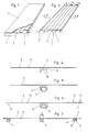
- the solar collector shown schematically in Fig. 1 has a collector housing, which has a frame 1 and a transparent cover 2.
- a collector housing which has a frame 1 and a transparent cover 2.
- an absorber according to the invention 3 arranged in the Collector housing.
- Behind the absorber is an insulating layer. 4
- the absorber 3 comprises an absorber plate made of an aluminum sheet 5 and a heat transfer medium leading pipe 6 made of copper.
- the absorber 3 has a single Absorber plate 5, whose width b is substantially over the entire inner Width of the absorber housing extends.
- the tube 6 runs meandering here on the extent of the absorber plate 5, wherein the sheet 7 over the edges the broad sides of the absorber plate 5 protrude.
- Such absorber with a individual absorber plate are also referred to as "plate absorber”.
- so-called "strip absorbers” are known in which several adjacent absorber plates are present. Such an embodiment The invention will be described below with reference to FIGS. 4 to 6.
- a so-called “harp piping” is known, namely both in connection with plate absorbers and strip absorbers.
- the individual pipe sections are not connected via arches, but over through lateral connecting pipes between which the area of Each absorber plate crossing pipes.
- the tube 6 with the absorber plate 5 are at the bottom of From an aluminum sheet existing absorber plate retaining strips 8 set.
- the retaining strips have 8 contact surfaces 9, each substantially extend over the entire width B of the retaining strip 8 and with which the Holding strips 8 over the entire surface of the underside of the absorber plate.
- a variety of metallic bonding techniques can be used, e.g. Laser welding, ultrasonic welding, soldering or sticking.
- the retaining strip 8 in the on the absorber plate 5 subsequent area with laterally projecting mounting flanges be provided with the contact surface 9 in turn on the entire width B of the retaining strip 8 may extend, so even across the width of Mounting flanges.
- a connection of the retaining strip 8 at the Absorber plate 5 by means of ultrasonic welding is by such (in Figs. Not illustrated) mounting flanges easier.
- the retaining strips 8 On their side facing away from the absorber plate 5 side, the retaining strips 8 in each case a groove-shaped depression 10, which in the longitudinal direction of the retaining strip 8 extends and extends over the entire longitudinal extension of the retaining strip 8.
- the enclosure angle of the pipe 6 is more than 180 °, whereby a mechanical anchoring of the tube 6 in the recess 10 is effected.
- the tube 6 is over the entire enclosure angle of the Pipe 6 on the wall of the channel-shaped recess 10 at.
- the trough-shaped depression as shown a has oval cross-section.
- the tube 6 in not flattened by the channel-shaped depression 10 section is flattened, this flattening being in a plane parallel to the plane of the absorber plate 5 is.
- the retaining strips 8 can conveniently aluminum extrusions be formed.
- an absorption surface 11 provided with a solar-selective coating is.
- a solar-selective coating allows the absorption of a high Proportion of short-wave solar radiation and its conversion into heat, at the same time the emission (radiation) of the long-wave heat radiation becomes the absorber is considerably reduced, i. through a solar-selective coating is the absorption coefficient for sunlight over the uncoated one Material increases and / or the emission coefficient of heat radiation is opposite reduced to the uncoated material.
- a solar-selectively coated absorber plate has an emission coefficient of heat radiation of less than 20%.
- FIGS. 4 to 6 The preparation of an absorber according to the invention is described below of the embodiment illustrated in FIGS. 4 to 6 explained.
- Absorbers designed as strip absorbers are a plurality of absorber units 12 present, of which in Fig. 6, only one absorber unit 12 is shown completely is.
- a respective absorber unit has an absorber plate 5, which in the already described manner may be formed.
- On the absorption surface 11 opposite side is on a respective absorber plate 5 a over attached the entire length of the absorber plate 5 continuous retaining strip 8, in which a to be flowed through by the heat transfer medium pipe 6, wherein the formation of the retaining strip 8 and the arrangement of the tube 6 in the retaining strip 8 may be the same as in the embodiment of FIGS. 2 and 3.
- the absorption surface 11 of the absorber plate 5 provided with a solar-selective coating.
- This coating can be done by PVD (Physical Vapor Deposition).
- the absorber plate 5 by a passage in a vacuum chamber introduced, in which the solar-selective coating in a continuous process takes place, wherein the absorber plate after coating through a bushing is led out of the vacuum chamber. Due to the flat, plate-shaped Formation of the absorber plate is a vacuum-tight implementation of the plate in and out of the vacuum chamber in a simple manner possible. In the episode will on the opposite side of the absorption surface, the retaining strip with a the already mentioned connection techniques attached (Fig. 4).
- the tube 6 which initially has a circular cross-section, in this groove inserted (Fig. 5) and in consequence by mechanical deformation applied to the wall of the channel-shaped depression 10 (FIG. 6). This is in the embodiment shown also also the flattening of the tube 6 in his not enclosed by the trough-shaped depression section attached.
- the tubes 6 of the individual absorber units 12 connected to each other, by arc 7th (in the case of meander piping) or through lateral connecting lines (in case of harp piping).
Landscapes
- Engineering & Computer Science (AREA)
- Chemical & Material Sciences (AREA)
- Sustainable Energy (AREA)
- Life Sciences & Earth Sciences (AREA)
- Physics & Mathematics (AREA)
- Sustainable Development (AREA)
- Dispersion Chemistry (AREA)
- Thermal Sciences (AREA)
- Combustion & Propulsion (AREA)
- Mechanical Engineering (AREA)
- General Engineering & Computer Science (AREA)
- Photovoltaic Devices (AREA)
- Building Environments (AREA)
Applications Claiming Priority (2)
| Application Number | Priority Date | Filing Date | Title |
|---|---|---|---|
| AT0162703A AT412908B (de) | 2003-10-16 | 2003-10-16 | Absorber für einen sonnenkollektor |
| AT16272003 | 2003-10-16 |
Publications (1)
| Publication Number | Publication Date |
|---|---|
| EP1524476A2 true EP1524476A2 (fr) | 2005-04-20 |
Family
ID=33569204
Family Applications (1)
| Application Number | Title | Priority Date | Filing Date |
|---|---|---|---|
| EP04017256A Withdrawn EP1524476A2 (fr) | 2003-10-16 | 2004-07-22 | Absorbeur pour collecteur solaire |
Country Status (2)
| Country | Link |
|---|---|
| EP (1) | EP1524476A2 (fr) |
| AT (1) | AT412908B (fr) |
Cited By (1)
| Publication number | Priority date | Publication date | Assignee | Title |
|---|---|---|---|---|
| WO2021140244A1 (fr) * | 2020-01-10 | 2021-07-15 | Institut Für Nachhaltigkeit - Förderverein Für Weiterbildung, Wissenschaft Und Forschung Für Kreative Nachhaltigkeit | Coque énergétique et bâtiment ainsi équipé |
Citations (5)
| Publication number | Priority date | Publication date | Assignee | Title |
|---|---|---|---|---|
| DE2522154A1 (de) | 1975-05-17 | 1976-11-25 | Eltreva Ag | Sonnenkollektor-segment |
| US4086913A (en) | 1976-12-15 | 1978-05-02 | Grumman Aerospace Corporation | Solar heat collector construction |
| DE2944805A1 (de) | 1978-11-06 | 1980-05-08 | Andrew Joseph Toti | Bauelement, verfahren zu seiner ausbildung und verwendung solcher bauelemente als tafelfoermige sonnenenergieabsorber |
| AT400196B (de) | 1992-03-05 | 1995-10-25 | Bertsch Gebhard | Sonnenkollektor |
| DE19505857A1 (de) | 1995-02-21 | 1996-08-22 | Bernd Dipl Ing Bartelsen | Sonnenkollektorelement |
-
2003
- 2003-10-16 AT AT0162703A patent/AT412908B/de not_active IP Right Cessation
-
2004
- 2004-07-22 EP EP04017256A patent/EP1524476A2/fr not_active Withdrawn
Patent Citations (5)
| Publication number | Priority date | Publication date | Assignee | Title |
|---|---|---|---|---|
| DE2522154A1 (de) | 1975-05-17 | 1976-11-25 | Eltreva Ag | Sonnenkollektor-segment |
| US4086913A (en) | 1976-12-15 | 1978-05-02 | Grumman Aerospace Corporation | Solar heat collector construction |
| DE2944805A1 (de) | 1978-11-06 | 1980-05-08 | Andrew Joseph Toti | Bauelement, verfahren zu seiner ausbildung und verwendung solcher bauelemente als tafelfoermige sonnenenergieabsorber |
| AT400196B (de) | 1992-03-05 | 1995-10-25 | Bertsch Gebhard | Sonnenkollektor |
| DE19505857A1 (de) | 1995-02-21 | 1996-08-22 | Bernd Dipl Ing Bartelsen | Sonnenkollektorelement |
Cited By (1)
| Publication number | Priority date | Publication date | Assignee | Title |
|---|---|---|---|---|
| WO2021140244A1 (fr) * | 2020-01-10 | 2021-07-15 | Institut Für Nachhaltigkeit - Förderverein Für Weiterbildung, Wissenschaft Und Forschung Für Kreative Nachhaltigkeit | Coque énergétique et bâtiment ainsi équipé |
Also Published As
| Publication number | Publication date |
|---|---|
| ATA16272003A (de) | 2005-01-15 |
| AT412908B (de) | 2005-08-25 |
Similar Documents
| Publication | Publication Date | Title |
|---|---|---|
| DE2720885A1 (de) | Sonnenkollektor | |
| DE102008064010A1 (de) | Fassadenelement mit plattenförmigem Thermosolarkollektor und Verfahren zur Herstellung und Anwendung | |
| DE102006009194A1 (de) | Anordnung aus einer tragenden Gebäudestruktur und einem Solarzellenaufbau | |
| DE102013008717A1 (de) | Flächenwärmetauscherelement, Verfahren zur Herstellung eines Flächenwärmetauscherelementes und Werkzeug | |
| EP0846245B1 (fr) | Collecteur de chaleur solaire | |
| EP0106262B1 (fr) | Echangeur thermique en particulier radiateur | |
| DE3010523A1 (de) | Waermetauscher fuer hausdaecher, fassaden, zaeune o.dgl. | |
| DE102008022391A1 (de) | Absorber, insbesondere für einen Sonnenkollektor und Verfahren zur Herstellung eines Absorbers für einen Sonnenkollektor | |
| DE10164670A1 (de) | Heliothermischer Flachkollektor-Modul | |
| EP3134699A1 (fr) | Dispositif échangeur de chaleur, collecteur solaire et tube thermique | |
| AT412908B (de) | Absorber für einen sonnenkollektor | |
| DE10043295C1 (de) | Heliothermischer Flachkollektor-Modul | |
| DE29521415U1 (de) | Solarkollektor | |
| AT509018B1 (de) | Flachabsorber | |
| DE29521278U1 (de) | Sonnenkollektor | |
| DE102011054194B4 (de) | Solarkollektor mit einer Vielzahl von rinnenförmigen Profilierungen | |
| CH707507A1 (de) | Klimaelement für eine Heiz- und Kühldecke. | |
| DE2633862A1 (de) | Sonnenkollektor | |
| DE2512226A1 (de) | Sonnenkollektor | |
| DE102004023140A1 (de) | Moduldach, insbesondere für Hallen und Wohngebäude | |
| EP2459940A2 (fr) | Absorbeur solaire et son procédé de production, collecteur solaire, installation solaire, lot de rattrapage et procédé de montage en rattrapage | |
| AT389937B (de) | Sonnenkollektor sowie verfahren zur herstellung des kollektorelementes | |
| DE3310326A1 (de) | Vorrichtung zum auffangen und zum uebertragen vorzugsweise solarer waerme auf ein stroemungsfaehiges waermetransportmittel | |
| DE2158505A1 (de) | Wärmetauschereinheit | |
| DE8006737U1 (de) | Flaechenwaermetauscher |
Legal Events
| Date | Code | Title | Description |
|---|---|---|---|
| PUAI | Public reference made under article 153(3) epc to a published international application that has entered the european phase |
Free format text: ORIGINAL CODE: 0009012 |
|
| AK | Designated contracting states |
Kind code of ref document: A2 Designated state(s): AT BE BG CH CY CZ DE DK EE ES FI FR GB GR HU IE IT LI LU MC NL PL PT RO SE SI SK TR |
|
| AX | Request for extension of the european patent |
Extension state: AL HR LT LV MK |
|
| STAA | Information on the status of an ep patent application or granted ep patent |
Free format text: STATUS: THE APPLICATION IS DEEMED TO BE WITHDRAWN |
|
| 18D | Application deemed to be withdrawn |
Effective date: 20070201 |