EP1524470B1 - Verfahren zur regelung einer thermodynamischen anlage - Google Patents
Verfahren zur regelung einer thermodynamischen anlage Download PDFInfo
- Publication number
- EP1524470B1 EP1524470B1 EP03023303A EP03023303A EP1524470B1 EP 1524470 B1 EP1524470 B1 EP 1524470B1 EP 03023303 A EP03023303 A EP 03023303A EP 03023303 A EP03023303 A EP 03023303A EP 1524470 B1 EP1524470 B1 EP 1524470B1
- Authority
- EP
- European Patent Office
- Prior art keywords
- spectrum
- flame
- characteristic value
- burner
- corresponds
- Prior art date
- Legal status (The legal status is an assumption and is not a legal conclusion. Google has not performed a legal analysis and makes no representation as to the accuracy of the status listed.)
- Expired - Lifetime
Links
- 238000000034 method Methods 0.000 title claims abstract description 14
- 239000000446 fuel Substances 0.000 claims abstract description 11
- 230000036962 time dependent Effects 0.000 claims abstract description 6
- 238000001228 spectrum Methods 0.000 claims description 23
- 238000009826 distribution Methods 0.000 claims description 11
- 238000012067 mathematical method Methods 0.000 claims description 3
- 238000005259 measurement Methods 0.000 abstract 2
- 239000003245 coal Substances 0.000 description 12
- 238000011156 evaluation Methods 0.000 description 7
- MWUXSHHQAYIFBG-UHFFFAOYSA-N nitrogen oxide Inorganic materials O=[N] MWUXSHHQAYIFBG-UHFFFAOYSA-N 0.000 description 3
- 239000002245 particle Substances 0.000 description 3
- 239000007789 gas Substances 0.000 description 2
- 238000005070 sampling Methods 0.000 description 2
- 241000273930 Brevoortia tyrannus Species 0.000 description 1
- 238000004220 aggregation Methods 0.000 description 1
- 230000002776 aggregation Effects 0.000 description 1
- 230000033228 biological regulation Effects 0.000 description 1
- 239000012141 concentrate Substances 0.000 description 1
- 230000001419 dependent effect Effects 0.000 description 1
- 239000000203 mixture Substances 0.000 description 1
- 239000003921 oil Substances 0.000 description 1
- 230000003287 optical effect Effects 0.000 description 1
- 238000005457 optimization Methods 0.000 description 1
- 230000035945 sensitivity Effects 0.000 description 1
- 239000004449 solid propellant Substances 0.000 description 1
- 230000003595 spectral effect Effects 0.000 description 1
- 230000009466 transformation Effects 0.000 description 1
Images
Classifications
-
- F—MECHANICAL ENGINEERING; LIGHTING; HEATING; WEAPONS; BLASTING
- F23—COMBUSTION APPARATUS; COMBUSTION PROCESSES
- F23N—REGULATING OR CONTROLLING COMBUSTION
- F23N5/00—Systems for controlling combustion
- F23N5/02—Systems for controlling combustion using devices responsive to thermal changes or to thermal expansion of a medium
- F23N5/08—Systems for controlling combustion using devices responsive to thermal changes or to thermal expansion of a medium using light-sensitive elements
- F23N5/082—Systems for controlling combustion using devices responsive to thermal changes or to thermal expansion of a medium using light-sensitive elements using electronic means
-
- F—MECHANICAL ENGINEERING; LIGHTING; HEATING; WEAPONS; BLASTING
- F23—COMBUSTION APPARATUS; COMBUSTION PROCESSES
- F23N—REGULATING OR CONTROLLING COMBUSTION
- F23N2229/00—Flame sensors
- F23N2229/20—Camera viewing
Definitions
- the invention relates to a method for controlling a thermodynamic system, having the features of the preamble of claim 1.
- each intended conveyor feeds the burner associated with it with an unknown distribution of the mass flows and the grain spectra of the coal serving as fuel, the unknown values making precise regulation very difficult.
- a measuring device will deduce the presence of an image of the flame for the presence of the flame.
- the US 4,913,647 A discloses a thermodynamic system in which a valve for the fuel is provided per flame, so that the distribution of the mass flows is known in principle or can be easily determined.
- the evaluation of "regions of interest" within an image of a flame is described in the WO 02/070953 A1 described.
- the present invention has for its object to improve a method of the type mentioned in terms of the amount of data. This object is achieved by a method having the features of claim 1. Further advantageous embodiments are the subject of the dependent claims.
- the application can be made in various thermodynamic systems, such as power plants, regardless of the fuel and its state of aggregation.
- the fuel may therefore be coal, oil or gas, for example.
- a spectrum is determined from the detected time-dependent signal, for example with a fast Fourier transformation or another mathematical method, from which five characteristic values are then determined. From the characteristic values, the com spectrum and / or the distribution of the mass flows per burner of each conveyor will be determined by multiple regression or another mathematical method. It is preferably the best possible approach to a combination of known fuel particle spectra and / or distributions of the mass flows pr.o burners each conveyor (for example, mill or pump), which are to be retired for initialization, ie the current fuel particle spectrum and / or the current distribution of mass flows.
- the fuel particle spectrum is a grain spectrum in the case of coal, and a droplet spectrum in the case of oil. In the case of gas, only the distribution of the mass flows is determined.
- a suitable measuring device which is used in the method according to the invention and which receives an image of the flame, has at least one diode, which respectively captures exactly one region of interest from the image of the flame, that is, confines itself to a part of the image. This reduces the to be detected and amount of data to be processed. In several areas of interest, a corresponding number of diodes are provided.
- the diode is preferably associated with an evaluation device, in particular its own evaluation device, which then preferably determines the spectrum and the characteristic values or the. The data volume to be forwarded is then minimal.
- the main computer can also act as the evaluation device, in which case, however, a field with data from the measuring device to the main computer is to be transmitted, which is larger in comparison with the characteristic values.
- a video camera is preferably provided, which is preferably selectively connectable to the measuring device. After adjustment, the video camera can be removed from the measuring device, which dampens the total cost of a larger system despite several measuring devices.
- the diode and the video camera preferably use the same optical access, for example a common borescope, to which a beam splitter is connected.
- a corresponding thermodynamic system which is controlled by the method according to the invention, has at least one measuring device except for a furnace and at least one conveyor, in particular a mill or pump, which are assigned to at least two burners, but preferably a measuring device for each burner.
- the fuel for a power plant is preferably coal, but other, especially solid fuels can be used, also as an admixture.
- a power plant 1 which is an example of a thermodynamic plant
- several bunkers 3 are provided with coarse-shaped coal concentrate, medium grain and fine grain, from which a mill 5 is charged as a conveyor.
- a mill 5 is charged as a conveyor.
- another fuel could be used or added.
- the coal K discharged from the mill 5 is fed together with the primary air L P to a burner 7 in a furnace 9, each mill 5, for reasons of cost, feeding several burners 7, for example two in the drawing. At each burner 7 then forms a flame 11 in the furnace 9. Below the burner 7, the secondary air L s is blown into the furnace 9.
- Each flame 11 is detected optically by a measuring device 15, which has a borescope 17 projecting into the oven 9, which images an image of the flame 11 into the interior of the measuring device 15.
- a beam splitter 19 By means of a beam splitter 19, the image of the flame 11 is directed on the one hand to a selectively connected to the measuring device 15 video camera 21 and on the other hand to a diode 23, which with a sampling frequency of, for example, up to 2 kHz - and optionally adjusted spectral sensitivity - a wedding or Optionally receives high-definition signal.
- the video camera 21 can be removed and used for the adjustment of another measuring device 15.
- the diode 23 preferably outputs the received signal to its own evaluation device 25, which carries out a subsequently described evaluation and forwards the result to a computer 31.
- This computer 31 is used to control the power plant 1, i. due to the results supplied by the measuring devices 15, different manipulated variables are actuated to achieve an optimization target, for example minimal emission of nitrogen oxides, for example, the coal mixture and quality fed to the mill 5, which have an influence on the grain spectrum of each burner 7, the amount of coal and the Amount of primary air and secondary air. Since different burners 7 are assigned to each mill 5, the effective manipulated variables are not all known.
- the recorded time-dependent signal is subjected to a fast Fourier transform and a Spectrum up to about 1000 Hz obtained (sampling theorem).
- the spectrum has an exponential decrease of intensity I in a range of about 100 to 1000 Hz and can be described in good approximation by five characteristic values.
- An initial departure from known grain spectra and known coal mass flow distributions serves the initialization and determination of the absolute values. From a multiple regression or other approximation process with the said five values from all burners 7 over time, a best approximation to a combination of known grain spectra and known coal mass flows can be achieved, from which the quantities desired for control are determined.
Landscapes
- Engineering & Computer Science (AREA)
- Chemical & Material Sciences (AREA)
- Combustion & Propulsion (AREA)
- Mechanical Engineering (AREA)
- General Engineering & Computer Science (AREA)
- Regulation And Control Of Combustion (AREA)
- Control Of Combustion (AREA)
- Confectionery (AREA)
Description
- Die Erfindung betrifft ein Verfahren zur Regelung einer thermodynamischen Anlage, mit den Merkmalen des Oberbegriffs des Anspruches 1.
- Bei einem aus der
DE 30 24 401 A1 bekannten Verfahren dieser Art beschickt jede vorgesehene Fördereinrichtung die ihr zugeordneten Brenner mit einer unbekannten Verteilung der Massenströme und der Kornspektren der als Brennstoff dienenden Kohle, wobei die unbekannten Werte eine exakte Regelung sehr erschweren. Bei jedem vorhandenen Brenner schließt eine Messvorrichtung aus dem Vorhandensein eines Bildes der Flamme auf das Vorhandensein der Flamme. - Die
US 4,913,647 A offenbart eine thermodynamische Anlage, bei der pro Flamme auch ein Ventil für den Brennstoff vorgesehen ist, so dass die Verteilung der Massenströme prinzipiell bekannt ist oder einfach ermittelt werden kann. Die Auswertung von "regions of interest" innerhalb eines Bildes einer Flamme wird in derWO 02/070953 A1 - Der vorliegenden Erfindung liegt die Aufgabe zugrunde, ein Verfahren der eingangs genannten Art hinsichtlich der Datenmenge zu verbessern. Diese Aufgabe wird durch ein Verfahren mit den Merkmalen des Anspruches 1 gelöst. Weitere vorteilhafte Ausgestaltungen sind Gegenstand der Unteransprüche.
- Indem vom Bild der Flamme wenigstens ein interessierendes Gebiet in der Flammenwurzel im Nahfeld des Brenners ausgewählt und dessen Intensität als zeitabhängiges Signal erfasst und zur Regelung verwendet wird, kann mit geringem Aufwand eine die Flamme in guter Näherung kennzeichnende kleine Datenmenge erfasst werden, die für die Regelung wichtige Informationen liefert. Es können auch mehrere interessierende Gebiete beobachtet werden. Aufgrund des beschränkten Umfangs der Datenmenge ist eine schnelle Verarbeitung sichergestellt. Die Anwendung kann bei verschiedenen thermodynamischen Anlagen, wie Kraftwerken, erfolgen, unabhängig vom Brennstoff und seinem Aggregatszustand. Der Brennstoff kann daher beispielsweise Kohle, Öl oder Gas sein.
- Zur Herausarbeitung der Merkmale der Flamme wird aus dem erfassten zeitabhängigen Signal ein Spektrum ermittelt, beispielsweise mit einer Fast-Fourier-Transformation oder einem anderen mathematischen Verfahren, aus welchem dann fünf charakteristische Werte ermittelt werden. Aus den charakteristischen Werten wird durch eine multiple Regression oder ein anderes mathematisches Verfahren das Komspektrum und/oder die Verteilung der Massen- , ströme pro Brenner jeder Fördereinrichtung ermittelt werden. Es handelt sich vorzugsweise um die bestmögliche Annäherung an eine Kombination bekannter Brennstoffpartikelspektren und/oder Verteilungen der Massenströme pr.o Brenner jeder Fördereinrichtung (beispielsweise Mühle oder Pumpe), welche zur Initalisierung vorab abzufahren sind, also das aktuelle Brennstoffpartikelspektrum und/oder die aktuelle Verteilung der Massenströme. Das Brennstoffpartikelspektrum ist im Falle von Kohle ein Kornspektrum, im Fall von Öl ein Tröpfchenspektrum. Im Falle von Gas wird nur die Verteilung der Massenströme ermittelt.
- Eine geeignete Messvorrichtung, welche bei dem erfindungsgemäßen Verfahren verwendet wird und welche ein Bild der Flamme erhält, weist wenigstens eine Diode auf, welche jeweils genau ein interessierendes Gebiet aus dem Bild der Flamme erfasst, also sich auf einen Teil des Bildes beschränkt. Dies verringert die zu erfassende und zu verarbeitende Datenmenge. Bei mehreren interessierenden Gebieten sind entsprechend viele Dioden vorgesehen. Der Diode ist vorzugsweise eine Auswerteeinrichtung zugeordnet, insbesondere eine eigene Auswerteeinrichtung, welche dann vorzugsweise das Spektrum und den oder die charakteristischen Werte ermittelt. Die weiterzuleitende Datenmenge ist dann minimal. Als Auswerteeinrichtung kann aber auch der Hauptcomputer fungieren, wobei dann allerdings ein - im Vergleich zu den charakteristischen Werten größeres - Feld mit Daten von der Meßvorrichtung an den Hauptcomputer zu übermitteln ist.
- Zum Justieren der Diode, d.h. zum Ausrichten derselben auf das interessierende Gebiet, ist vorzugsweise eine Videokamera vorgesehen, die vorzugsweise wahlweise an die Meßvorrichtung anschließbar ist. Nach dem Justieren kann die Videokamera von der Meßvorrichtung entfernt werden, was die Gesamtkosten bei einer größeren Anlage trotz mehrerer Meßvorrichtungen dämpft. Zur Vereinfachung des Justierens benutzen die Diode und die Videokamera vorzugsweise den gleichen optischen Zugang, beispielsweise ein gemeinsames Boroskop, an welches ein Strahlteiler angeschlossen ist.
- Eine entsprechende thermodynamische Anlage, welche mit dem erfindungsgemäßen Verfahren geregelt wird, weist außer einem Ofen und wenigstens einer Fördereinrichtung, insbesondere einer Mühle oder Pumpe, der wenigstens zwei Brenner zugeordnet sind, wenigstens eine Meßvorrichtung auf, vorzugsweise jedoch für jeden Brenner eine Meßvorrichtung. Der Brennstoff für ein Kraftwerk ist vorzugsweise Kohle, jedoch können auch andere, insbesondere feste Brennstoffe verwendet werden, auch als Beimischung.
- Im folgenden ist die Erfindung anhand eines in der Zeichnung dargestellten Ausführungsbeispiels näher erläutert. Es zeigen
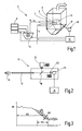
- Fig. 1
- eine schematische Darstellung eines Kraftwerk,
- Fig. 2
- eine schematische Darstellung einer Meßvorrichtung, und
- Fig. 3
- ein Spektrum der Intensität in einem ausgewählten Gebiet einer Flamme.
- In einem Kraftwerk 1, welches ein Beispiel einer thermodynamischen Anlage ist, sind mehrere Bunker 3 mit grobkörmigem Kohlekonzentrat, Mittelkorn und Feinkorn vorgesehen, aus welchen eine Mühle 5 als Fördereinrichtung beschickt wird. Statt Kohle könnte im Prinzip auch ein anderer Brennstoff verwendet oder beigemischt werden. Die von der Mühle 5 ausgegebene Kohle K wird zusammen mit der Primärluft LP einem Brenner 7 in einem Ofen 9 zugeführt, wobei jede Mühle 5 aus Kostengründen mehrere Brenner 7, in der Zeichnung beispielsweise zwei Stück, beschickt. An jedem Brenner 7 bildet sich dann im Ofen 9 eine Flamme 11 aus. Unterhalb der Brenner 7 wird die Sekundärluft Ls in den Ofen 9 geblasen.
- Jede Flamme 11 wird optische von einer Meßvorrichtung 15 erfaßt, welche ein in den Ofen 9 ragendes Boroskop 17 aufweist, das ein Bild der Flamme 11 in das Innere der Meßvorrichtung 15 abbildet. Mittels eines Strahlteilers 19 wird das Bild der Flamme 11 einerseits auf eine wahlweise an die Meßvorrichtung 15 angeschlossene Videokamera 21 und andererseits auf eine Diode 23 gelenkt, welche mit einer Abtastfrequenz von beispielsweise bis zu 2 kHz - und gegebenenfalls angepaßter spektraler Empfindlichkeit - ein hochzeit- oder optional hochspektralaufgelöstes Signal aufnimmt. Dabei ist das Boroskop 17 mit Hilfe der Videokamera 21 so justiert, daß die Diode 23 auf ein interessierendes Gebiet (ROI = Region of interest) in der Flammenwurzel im Nahfeld des Brenners 7 ausgerichtet ist, welche in der Zeichnung schematisch durch ein Kreuz symbolisiert ist. Nach dem Justieren kann die Videokamera 21 entfernt und für die Justierung einer anderen Meßvorrichtung 15 verwendet werden.
- Die Diode 23 gibt das empfangene Signal vorzugsweise an eine eigene Auswerteeinrichtung 25, welche eine nachfolgend beschriebe Auswertung vornimmt und das Ergebnis an einen Computer 31 weitergibt. Dieser Computer 31 dient der Regelung des Kraftwerks 1, d.h. aufgrund der von den Meßvorrichtungen 15 gelieferten Ergebnisse werden zur Erreichung eines Optimierungszieles, beispielsweise minimalem Ausstoß von Stickoxiden, verschiedene Stellgrößen betätigt, beispielsweise die der Mühle 5 zugeführte Kohlemischung und -qualität, welche einen Einfluß auf das Kornspektrum jedes Brenners 7 haben, die Kohlemenge und die Menge der Primärluft und der Sekundärluft. Da verschiedene Brenner 7 jeder Mühle 5 zugeordnet sind, sind die wirksamen Stellgrößen nicht alle bekannt.
- Um daher das Kornspektrum an jedem Brenner 7 sowie die Verteilung der Kohlemassenströme auf die verschiedenen Brenner 7 einer Mühle 5 zu ermitteln, wird in der Auswerteeinrichtung 25 jeder Diode 23 oder optional im Computer 31 das aufgenommene zeitabhängige Signal einer Fast-Fourier-Transformation unterzogen und ein Spektrum bis etwa 1000 Hz erhalten (Sampling-Theorem). Das Spektrum weist in einem Bereich von etwa 100 bis 1000 Hz einen exponentiellen Abfall der Intensität I auf und kann in guter Näherung durch fünf charakteristische Werte beschrieben werden.
- Diese fünf charakteristischen Werte sind der frequenzunabhängige, konstante Intensitätsanteil M1, welcher der Intensität I bei der Frequenz f=0 entspricht, der mittlere Frequenzwert M2 im Bereich des Intensitätsabfalls, d.h. der Abstand des Bereichs des Intensitätsabfalls von der Frequenz f=0, die Lage und Breite M3 (alternativ Minimal- und Maximalwert) des Bereichs des Intensitätsabfalls, der Regressionskoeffizient M4, d.h. die Steigung im Bereich des Intensitätsabfalls und die Streuung M5, d.h. die Bandbreite der Intensität im Bereich des Intensitätsabfalls. Ein anfängliches Abfahren bekannter Kornspektren und bekannter Kohlemassenstromverteilungen dient der Initialisierung und Bestimmung der absoluten Werte. Aus einer multiplen Regression oder einem anderen Annäherungsverfahren mit den genannten fünf Werten von allen Brennern 7 über die Zeit hinweg kann eine bestmögliche Annäherung an eine Kombination der bekannten Kornspektren und bekannten Kohlemassenströme erreicht werden, aus der die für die Regelung erwünschten Größen ermittelt werden.
Claims (3)
- Verfahren zur Regelung einer thermodynamischen Anlage (1), gemäß dem wenigstens eine Fördereinrichtung (5) jeweils wenigstens zwei ihr zugeordnete Brenner (7) mit Brennstoff beschickt und bei jedem vorhandenen Brenner (7) das Bild einer sich ausbildenden Flamme (11) erfasst und verarbeitet wird, wobei vom Bild der Flamme (11) wenigstens ein interessierendes Gebiet in der Flammenwurzel im Nahfeld des Brenners (7) ausgewählt und dessen Intensität (I) als zeitabhängiges Signal erfasst und zur Regelung verwendet wird, dadurch gekennzeichnet, dass aus dem erfassten zeitabhängigen Signal ein Spektrum und hieraus charakteristische Werte (M1, M2, M3, M4, M5) ermittelt werden, aus denen durch eine Regression oder ein anderes mathematisches Verfahren das Kornspektrum und/oder die Verteilung der Massenströme pro Brenner (7) jeder Fördereinrichtung (5) ermittelt werden, wobei im Spektrum die Intensität (I) bei der Frequenz f=0 der erste charakteristische Wert (M1), bezüglich des Bereichs eines Intensitätsabfalls des Spektrums ein mittlerer Frequenzwert der zweite charakteristische Wert (M2), die Lage und Breite dieses Bereichs der dritte charakteristische Werte (M3), der Regressionskoeffizient der vierte charakteristische Werte (M4) und die Streuung der fünfte charakteristische Werte (M5) sind.
- Verfahren nach Anspruch 1, dadurch gekennzeichnet, dass ein anfängliches Abfahren bekannter Kornspektren und bekannter Verteilung der Massenströme der Initialisierung und Bestimmung der absoluten Werte dient.
- Verfahren nach Anspruch 2, dadurch gekennzeichnet, dass aus den charakteristischen Werten (M1, M2, M3, M4, M5) von allen Brennern (7) über die Zeit hinweg eine Annäherung an eine Kombination der bekannten Kornspektren und bekannten Verteilung der Massenströme erreicht wird.
Priority Applications (5)
| Application Number | Priority Date | Filing Date | Title |
|---|---|---|---|
| ES03023303T ES2358585T3 (es) | 2003-10-15 | 2003-10-15 | Procedimiento para la regulación de una instalación termodinámica. |
| AT03023303T ATE497128T1 (de) | 2003-10-15 | 2003-10-15 | Verfahren zur regelung einer thermodynamischen anlage |
| EP03023303A EP1524470B1 (de) | 2003-10-15 | 2003-10-15 | Verfahren zur regelung einer thermodynamischen anlage |
| DE50313441T DE50313441D1 (de) | 2003-10-15 | 2003-10-15 | Verfahren zur regelung einer thermodynamischen anlage |
| KR1020040082147A KR101115758B1 (ko) | 2003-10-15 | 2004-10-14 | 열역학적 시스템 제어 방법 |
Applications Claiming Priority (1)
| Application Number | Priority Date | Filing Date | Title |
|---|---|---|---|
| EP03023303A EP1524470B1 (de) | 2003-10-15 | 2003-10-15 | Verfahren zur regelung einer thermodynamischen anlage |
Publications (2)
| Publication Number | Publication Date |
|---|---|
| EP1524470A1 EP1524470A1 (de) | 2005-04-20 |
| EP1524470B1 true EP1524470B1 (de) | 2011-01-26 |
Family
ID=34354455
Family Applications (1)
| Application Number | Title | Priority Date | Filing Date |
|---|---|---|---|
| EP03023303A Expired - Lifetime EP1524470B1 (de) | 2003-10-15 | 2003-10-15 | Verfahren zur regelung einer thermodynamischen anlage |
Country Status (5)
| Country | Link |
|---|---|
| EP (1) | EP1524470B1 (de) |
| KR (1) | KR101115758B1 (de) |
| AT (1) | ATE497128T1 (de) |
| DE (1) | DE50313441D1 (de) |
| ES (1) | ES2358585T3 (de) |
Families Citing this family (2)
| Publication number | Priority date | Publication date | Assignee | Title |
|---|---|---|---|---|
| ES2313488T3 (es) | 2006-04-25 | 2009-03-01 | Powitec Intelligent Technologies Gmbh | Procedimiento y bucle de regulacion para regular un proceso de combustion. |
| CN108445746B (zh) * | 2018-01-25 | 2020-12-29 | 北京农业信息技术研究中心 | 一种智能投喂控制方法及装置 |
Family Cites Families (4)
| Publication number | Priority date | Publication date | Assignee | Title |
|---|---|---|---|---|
| DE3024401A1 (de) * | 1980-06-28 | 1982-01-28 | Steag Ag, 4300 Essen | Verfahren zur gesteuerten verbrennung von festen fossilen brennstoffen, insbesondere kohlestaub |
| US4913647A (en) * | 1986-03-19 | 1990-04-03 | Honeywell Inc. | Air fuel ratio control |
| DE10143548A1 (de) * | 2001-06-13 | 2003-01-02 | Powitec Intelligent Tech Gmbh | Meßvorrichtung, insbesondere zur Flammenbeobachtung während eines Verbrennungsprozesses |
| ATE293232T1 (de) * | 2001-03-02 | 2005-04-15 | Powitec Intelligent Tech Gmbh | Messvorrichtung, insbesondere zur flammenbeobachtung während eines verbrennungsprozesses |
-
2003
- 2003-10-15 EP EP03023303A patent/EP1524470B1/de not_active Expired - Lifetime
- 2003-10-15 AT AT03023303T patent/ATE497128T1/de active
- 2003-10-15 DE DE50313441T patent/DE50313441D1/de not_active Expired - Lifetime
- 2003-10-15 ES ES03023303T patent/ES2358585T3/es not_active Expired - Lifetime
-
2004
- 2004-10-14 KR KR1020040082147A patent/KR101115758B1/ko not_active Expired - Fee Related
Also Published As
| Publication number | Publication date |
|---|---|
| ES2358585T3 (es) | 2011-05-12 |
| DE50313441D1 (de) | 2011-03-10 |
| KR101115758B1 (ko) | 2012-03-06 |
| KR20050036777A (ko) | 2005-04-20 |
| ATE497128T1 (de) | 2011-02-15 |
| EP1524470A1 (de) | 2005-04-20 |
Similar Documents
| Publication | Publication Date | Title |
|---|---|---|
| DE102007032176B4 (de) | Induktiv gekoppeltes Plasmamassenspektrometer | |
| DE102015111889B4 (de) | Verfahren zur Prüfung einer landwirtschaftlichen Sprüheinrichtung | |
| DE102015000632A1 (de) | Regelung des Strahlmitteldurchsatzes einer Strahlanlage | |
| DE102007032665A1 (de) | Verfahren und Vorrichtung zur Durchführung einer Brennprüfung an einem Prüfling | |
| EP3703867A1 (de) | Verfahren und lackiersystem zum lackieren eines werkstücks mit einem zerstäuber | |
| DE202019005858U1 (de) | Kühlsystem für Entschichter | |
| WO2017220456A1 (de) | Vorrichtung und verfahren zur wärmebehandlung von mineralischem gut | |
| EP0780160A1 (de) | Pulver-Sprühbeschichtungsvorrichtung | |
| EP1524470B1 (de) | Verfahren zur regelung einer thermodynamischen anlage | |
| EP3403027B1 (de) | Auswerte- und regelungsverfahren für mehrstoffbrenner | |
| DE102009060454B4 (de) | Vorrichtung zur Aerosolerzeugung | |
| WO2016116367A1 (de) | Verfahren und beschichtungsanlage zum beschichten von hohlraumwänden | |
| EP1048900A1 (de) | Verfahren und Vorrichtung zum Steuern der Verbrennung von Brennstoff mit variablem Heizwert | |
| WO2021226649A1 (de) | Verfahren zur staubniederhaltung bei brechern mit sprüheinrichtungen | |
| DE102014116019A1 (de) | Verfahren und Vorrichtung zur Berechnung von Einstellparametern eines Schleuderstreuers | |
| DE102018218006A1 (de) | Verfahren und Vorrichtung zur Überwachung eines Schneidprozesses | |
| EP0718555A1 (de) | Verfahren und Vorrichtung zur Verbrennung von Abfällen | |
| EP3886560A1 (de) | Verfahren zum bestimmen von eigenschaften landwirtschaftlichen streuguts | |
| DE10220773A1 (de) | Verfahren und Einrichtung zur Regelung eines Verbrennungsprozesses, insbesondere eines Brenners | |
| EP1934528B1 (de) | Verfahren und vorrichtung zur überwachung sich bildender ablagerungen von feststoffteilchen, insbesondere in einer brennstoffleitung sowie in den brennstoffventilen einer gasturbine | |
| EP3556209B1 (de) | Verfahren und vorrichtung zur abstandsmessung an einem landwirtschaftlichen verteilergestänge | |
| DE19640671C1 (de) | Dreibereichs-Verfahren zur analogen Farberkennung und Vorrichtung zum Durchführen des Verfahrens | |
| DE202009017542U1 (de) | Vorrichtung zur Aerosolerzeugung | |
| DE3331478A1 (de) | Verfahren und vorrichtung zur optischen ueberwachung von flammen | |
| EP0734779A2 (de) | Elektrostatische Sprühbeschichtungseinrichtung |
Legal Events
| Date | Code | Title | Description |
|---|---|---|---|
| PUAI | Public reference made under article 153(3) epc to a published international application that has entered the european phase |
Free format text: ORIGINAL CODE: 0009012 |
|
| AK | Designated contracting states |
Kind code of ref document: A1 Designated state(s): AT BE BG CH CY CZ DE DK EE ES FI FR GB GR HU IE IT LI LU MC NL PT RO SE SI SK TR |
|
| AX | Request for extension of the european patent |
Extension state: AL LT LV MK |
|
| 17P | Request for examination filed |
Effective date: 20050725 |
|
| AKX | Designation fees paid |
Designated state(s): AT BE BG CH CY CZ DE DK EE ES FI FR GB GR HU IE IT LI LU MC NL PT RO SE SI SK TR |
|
| 17Q | First examination report despatched |
Effective date: 20090709 |
|
| GRAP | Despatch of communication of intention to grant a patent |
Free format text: ORIGINAL CODE: EPIDOSNIGR1 |
|
| RTI1 | Title (correction) |
Free format text: METHOD FOR CONTROLLING A THERMODYNAMIC SYSTEM |
|
| GRAC | Information related to communication of intention to grant a patent modified |
Free format text: ORIGINAL CODE: EPIDOSCIGR1 |
|
| RIN1 | Information on inventor provided before grant (corrected) |
Inventor name: WINTRICH, FRANZ Inventor name: RICHTER, PETER |
|
| RTI1 | Title (correction) |
Free format text: METHOD FOR CONTROLLING A THERMODYNAMIC SYSTEM |
|
| GRAS | Grant fee paid |
Free format text: ORIGINAL CODE: EPIDOSNIGR3 |
|
| GRAA | (expected) grant |
Free format text: ORIGINAL CODE: 0009210 |
|
| AK | Designated contracting states |
Kind code of ref document: B1 Designated state(s): AT BE BG CH CY CZ DE DK EE ES FI FR GB GR HU IE IT LI LU MC NL PT RO SE SI SK TR |
|
| REG | Reference to a national code |
Ref country code: GB Ref legal event code: FG4D Free format text: NOT ENGLISH |
|
| REG | Reference to a national code |
Ref country code: CH Ref legal event code: EP |
|
| REG | Reference to a national code |
Ref country code: IE Ref legal event code: FG4D Free format text: LANGUAGE OF EP DOCUMENT: GERMAN |
|
| REF | Corresponds to: |
Ref document number: 50313441 Country of ref document: DE Date of ref document: 20110310 Kind code of ref document: P |
|
| REG | Reference to a national code |
Ref country code: DE Ref legal event code: R096 Ref document number: 50313441 Country of ref document: DE Effective date: 20110310 |
|
| REG | Reference to a national code |
Ref country code: ES Ref legal event code: FG2A Ref document number: 2358585 Country of ref document: ES Kind code of ref document: T3 Effective date: 20110429 |
|
| REG | Reference to a national code |
Ref country code: GR Ref legal event code: EP Ref document number: 20110400649 Country of ref document: GR Effective date: 20110412 |
|
| REG | Reference to a national code |
Ref country code: NL Ref legal event code: VDEP Effective date: 20110126 |
|
| REG | Reference to a national code |
Ref country code: SK Ref legal event code: T3 Ref document number: E 9137 Country of ref document: SK |
|
| PG25 | Lapsed in a contracting state [announced via postgrant information from national office to epo] |
Ref country code: PT Free format text: LAPSE BECAUSE OF FAILURE TO SUBMIT A TRANSLATION OF THE DESCRIPTION OR TO PAY THE FEE WITHIN THE PRESCRIBED TIME-LIMIT Effective date: 20110526 Ref country code: SE Free format text: LAPSE BECAUSE OF FAILURE TO SUBMIT A TRANSLATION OF THE DESCRIPTION OR TO PAY THE FEE WITHIN THE PRESCRIBED TIME-LIMIT Effective date: 20110126 |
|
| REG | Reference to a national code |
Ref country code: IE Ref legal event code: FD4D |
|
| PG25 | Lapsed in a contracting state [announced via postgrant information from national office to epo] |
Ref country code: BG Free format text: LAPSE BECAUSE OF FAILURE TO SUBMIT A TRANSLATION OF THE DESCRIPTION OR TO PAY THE FEE WITHIN THE PRESCRIBED TIME-LIMIT Effective date: 20110426 Ref country code: FI Free format text: LAPSE BECAUSE OF FAILURE TO SUBMIT A TRANSLATION OF THE DESCRIPTION OR TO PAY THE FEE WITHIN THE PRESCRIBED TIME-LIMIT Effective date: 20110126 Ref country code: NL Free format text: LAPSE BECAUSE OF FAILURE TO SUBMIT A TRANSLATION OF THE DESCRIPTION OR TO PAY THE FEE WITHIN THE PRESCRIBED TIME-LIMIT Effective date: 20110126 Ref country code: CY Free format text: LAPSE BECAUSE OF FAILURE TO SUBMIT A TRANSLATION OF THE DESCRIPTION OR TO PAY THE FEE WITHIN THE PRESCRIBED TIME-LIMIT Effective date: 20110126 Ref country code: SI Free format text: LAPSE BECAUSE OF FAILURE TO SUBMIT A TRANSLATION OF THE DESCRIPTION OR TO PAY THE FEE WITHIN THE PRESCRIBED TIME-LIMIT Effective date: 20110126 |
|
| PG25 | Lapsed in a contracting state [announced via postgrant information from national office to epo] |
Ref country code: DK Free format text: LAPSE BECAUSE OF FAILURE TO SUBMIT A TRANSLATION OF THE DESCRIPTION OR TO PAY THE FEE WITHIN THE PRESCRIBED TIME-LIMIT Effective date: 20110126 Ref country code: IE Free format text: LAPSE BECAUSE OF FAILURE TO SUBMIT A TRANSLATION OF THE DESCRIPTION OR TO PAY THE FEE WITHIN THE PRESCRIBED TIME-LIMIT Effective date: 20110126 Ref country code: EE Free format text: LAPSE BECAUSE OF FAILURE TO SUBMIT A TRANSLATION OF THE DESCRIPTION OR TO PAY THE FEE WITHIN THE PRESCRIBED TIME-LIMIT Effective date: 20110126 |
|
| PG25 | Lapsed in a contracting state [announced via postgrant information from national office to epo] |
Ref country code: RO Free format text: LAPSE BECAUSE OF FAILURE TO SUBMIT A TRANSLATION OF THE DESCRIPTION OR TO PAY THE FEE WITHIN THE PRESCRIBED TIME-LIMIT Effective date: 20110126 |
|
| PLBE | No opposition filed within time limit |
Free format text: ORIGINAL CODE: 0009261 |
|
| STAA | Information on the status of an ep patent application or granted ep patent |
Free format text: STATUS: NO OPPOSITION FILED WITHIN TIME LIMIT |
|
| 26N | No opposition filed |
Effective date: 20111027 |
|
| REG | Reference to a national code |
Ref country code: DE Ref legal event code: R097 Ref document number: 50313441 Country of ref document: DE Effective date: 20111027 |
|
| BERE | Be: lapsed |
Owner name: POWITEC INTELLIGENT TECHNOLOGIES G.M.B.H. Effective date: 20111031 |
|
| PG25 | Lapsed in a contracting state [announced via postgrant information from national office to epo] |
Ref country code: MC Free format text: LAPSE BECAUSE OF NON-PAYMENT OF DUE FEES Effective date: 20111031 |
|
| REG | Reference to a national code |
Ref country code: CH Ref legal event code: PL |
|
| PG25 | Lapsed in a contracting state [announced via postgrant information from national office to epo] |
Ref country code: LI Free format text: LAPSE BECAUSE OF NON-PAYMENT OF DUE FEES Effective date: 20111031 Ref country code: BE Free format text: LAPSE BECAUSE OF NON-PAYMENT OF DUE FEES Effective date: 20111031 Ref country code: CH Free format text: LAPSE BECAUSE OF NON-PAYMENT OF DUE FEES Effective date: 20111031 |
|
| REG | Reference to a national code |
Ref country code: AT Ref legal event code: MM01 Ref document number: 497128 Country of ref document: AT Kind code of ref document: T Effective date: 20111015 |
|
| PG25 | Lapsed in a contracting state [announced via postgrant information from national office to epo] |
Ref country code: AT Free format text: LAPSE BECAUSE OF NON-PAYMENT OF DUE FEES Effective date: 20111015 |
|
| REG | Reference to a national code |
Ref country code: DE Ref legal event code: R082 Ref document number: 50313441 Country of ref document: DE Representative=s name: HOSENTHIEN-HELD UND DR. HELD, DE |
|
| PG25 | Lapsed in a contracting state [announced via postgrant information from national office to epo] |
Ref country code: LU Free format text: LAPSE BECAUSE OF NON-PAYMENT OF DUE FEES Effective date: 20111015 |
|
| REG | Reference to a national code |
Ref country code: DE Ref legal event code: R081 Ref document number: 50313441 Country of ref document: DE Owner name: STEAG POWITEC GMBH, DE Free format text: FORMER OWNER: POWITEC INTELLIGENT TECHNOLOGIES GMBH, 45219 ESSEN, DE Effective date: 20130424 Ref country code: DE Ref legal event code: R081 Ref document number: 50313441 Country of ref document: DE Owner name: STEAG ENERGY SERVICES GMBH, DE Free format text: FORMER OWNER: POWITEC INTELLIGENT TECHNOLOGIES GMBH, 45219 ESSEN, DE Effective date: 20130424 Ref country code: DE Ref legal event code: R082 Ref document number: 50313441 Country of ref document: DE Representative=s name: HOSENTHIEN-HELD UND DR. HELD, DE Effective date: 20130424 |
|
| PG25 | Lapsed in a contracting state [announced via postgrant information from national office to epo] |
Ref country code: HU Free format text: LAPSE BECAUSE OF FAILURE TO SUBMIT A TRANSLATION OF THE DESCRIPTION OR TO PAY THE FEE WITHIN THE PRESCRIBED TIME-LIMIT Effective date: 20110126 |
|
| PGFP | Annual fee paid to national office [announced via postgrant information from national office to epo] |
Ref country code: SK Payment date: 20131002 Year of fee payment: 11 Ref country code: FR Payment date: 20131024 Year of fee payment: 11 Ref country code: CZ Payment date: 20131007 Year of fee payment: 11 Ref country code: GB Payment date: 20131001 Year of fee payment: 11 |
|
| PGFP | Annual fee paid to national office [announced via postgrant information from national office to epo] |
Ref country code: TR Payment date: 20131007 Year of fee payment: 11 Ref country code: GR Payment date: 20131031 Year of fee payment: 11 Ref country code: ES Payment date: 20131014 Year of fee payment: 11 Ref country code: IT Payment date: 20131025 Year of fee payment: 11 |
|
| GBPC | Gb: european patent ceased through non-payment of renewal fee |
Effective date: 20141015 |
|
| REG | Reference to a national code |
Ref country code: GR Ref legal event code: ML Ref document number: 20110400649 Country of ref document: GR Effective date: 20150505 |
|
| REG | Reference to a national code |
Ref country code: SK Ref legal event code: MM4A Ref document number: E 9137 Country of ref document: SK Effective date: 20141015 |
|
| PG25 | Lapsed in a contracting state [announced via postgrant information from national office to epo] |
Ref country code: GB Free format text: LAPSE BECAUSE OF NON-PAYMENT OF DUE FEES Effective date: 20141015 Ref country code: CZ Free format text: LAPSE BECAUSE OF NON-PAYMENT OF DUE FEES Effective date: 20141015 Ref country code: SK Free format text: LAPSE BECAUSE OF NON-PAYMENT OF DUE FEES Effective date: 20141015 |
|
| REG | Reference to a national code |
Ref country code: FR Ref legal event code: ST Effective date: 20150630 |
|
| PG25 | Lapsed in a contracting state [announced via postgrant information from national office to epo] |
Ref country code: FR Free format text: LAPSE BECAUSE OF NON-PAYMENT OF DUE FEES Effective date: 20141031 Ref country code: IT Free format text: LAPSE BECAUSE OF NON-PAYMENT OF DUE FEES Effective date: 20141015 Ref country code: GR Free format text: LAPSE BECAUSE OF NON-PAYMENT OF DUE FEES Effective date: 20150505 |
|
| REG | Reference to a national code |
Ref country code: ES Ref legal event code: FD2A Effective date: 20151126 |
|
| PG25 | Lapsed in a contracting state [announced via postgrant information from national office to epo] |
Ref country code: ES Free format text: LAPSE BECAUSE OF NON-PAYMENT OF DUE FEES Effective date: 20141016 |
|
| REG | Reference to a national code |
Ref country code: DE Ref legal event code: R081 Ref document number: 50313441 Country of ref document: DE Owner name: STEAG ENERGY SERVICES GMBH, DE Free format text: FORMER OWNER: STEAG POWITEC GMBH, 45219 ESSEN, DE Ref country code: DE Ref legal event code: R082 Ref document number: 50313441 Country of ref document: DE Representative=s name: HOSENTHIEN-HELD UND DR. HELD, DE Ref country code: DE Ref legal event code: R081 Ref document number: 50313441 Country of ref document: DE Owner name: STEAG POWITEC GMBH, DE Free format text: FORMER OWNER: STEAG POWITEC GMBH, 45219 ESSEN, DE |
|
| REG | Reference to a national code |
Ref country code: DE Ref legal event code: R082 Ref document number: 50313441 Country of ref document: DE Representative=s name: HOSENTHIEN-HELD UND DR. HELD, DE Ref country code: DE Ref legal event code: R081 Ref document number: 50313441 Country of ref document: DE Owner name: STEAG ENERGY SERVICES GMBH, DE Free format text: FORMER OWNER: STEAG POWITEC GMBH, 45128 ESSEN, DE |
|
| PG25 | Lapsed in a contracting state [announced via postgrant information from national office to epo] |
Ref country code: TR Free format text: LAPSE BECAUSE OF NON-PAYMENT OF DUE FEES Effective date: 20141015 |
|
| PGFP | Annual fee paid to national office [announced via postgrant information from national office to epo] |
Ref country code: DE Payment date: 20200907 Year of fee payment: 18 |
|
| REG | Reference to a national code |
Ref country code: DE Ref legal event code: R119 Ref document number: 50313441 Country of ref document: DE |
|
| PG25 | Lapsed in a contracting state [announced via postgrant information from national office to epo] |
Ref country code: DE Free format text: LAPSE BECAUSE OF NON-PAYMENT OF DUE FEES Effective date: 20220503 |