EP1524416A1 - Elektrostatisches Filtersystem von Abgasrusspartikeln einer Brennkraftmaschine und Verfahren zur Regenerierung eines solchen Systems - Google Patents
Elektrostatisches Filtersystem von Abgasrusspartikeln einer Brennkraftmaschine und Verfahren zur Regenerierung eines solchen Systems Download PDFInfo
- Publication number
- EP1524416A1 EP1524416A1 EP04300664A EP04300664A EP1524416A1 EP 1524416 A1 EP1524416 A1 EP 1524416A1 EP 04300664 A EP04300664 A EP 04300664A EP 04300664 A EP04300664 A EP 04300664A EP 1524416 A1 EP1524416 A1 EP 1524416A1
- Authority
- EP
- European Patent Office
- Prior art keywords
- electrode
- regeneration
- porous
- filtration
- cell
- Prior art date
- Legal status (The legal status is an assumption and is not a legal conclusion. Google has not performed a legal analysis and makes no representation as to the accuracy of the status listed.)
- Withdrawn
Links
Images


Classifications
-
- B—PERFORMING OPERATIONS; TRANSPORTING
- B01—PHYSICAL OR CHEMICAL PROCESSES OR APPARATUS IN GENERAL
- B01D—SEPARATION
- B01D46/00—Filters or filtering processes specially modified for separating dispersed particles from gases or vapours
- B01D46/24—Particle separators, e.g. dust precipitators, using rigid hollow filter bodies
- B01D46/2403—Particle separators, e.g. dust precipitators, using rigid hollow filter bodies characterised by the physical shape or structure of the filtering element
-
- B—PERFORMING OPERATIONS; TRANSPORTING
- B01—PHYSICAL OR CHEMICAL PROCESSES OR APPARATUS IN GENERAL
- B01D—SEPARATION
- B01D46/00—Filters or filtering processes specially modified for separating dispersed particles from gases or vapours
- B01D46/42—Auxiliary equipment or operation thereof
- B01D46/50—Means for discharging electrostatic potential
-
- B—PERFORMING OPERATIONS; TRANSPORTING
- B01—PHYSICAL OR CHEMICAL PROCESSES OR APPARATUS IN GENERAL
- B01D—SEPARATION
- B01D46/00—Filters or filtering processes specially modified for separating dispersed particles from gases or vapours
- B01D46/66—Regeneration of the filtering material or filter elements inside the filter
- B01D46/80—Chemical processes for the removal of the retained particles, e.g. by burning
- B01D46/84—Chemical processes for the removal of the retained particles, e.g. by burning by heating only
-
- F—MECHANICAL ENGINEERING; LIGHTING; HEATING; WEAPONS; BLASTING
- F01—MACHINES OR ENGINES IN GENERAL; ENGINE PLANTS IN GENERAL; STEAM ENGINES
- F01N—GAS-FLOW SILENCERS OR EXHAUST APPARATUS FOR MACHINES OR ENGINES IN GENERAL; GAS-FLOW SILENCERS OR EXHAUST APPARATUS FOR INTERNAL-COMBUSTION ENGINES
- F01N13/00—Exhaust or silencing apparatus characterised by constructional features
- F01N13/011—Exhaust or silencing apparatus characterised by constructional features having two or more purifying devices arranged in parallel
-
- F—MECHANICAL ENGINEERING; LIGHTING; HEATING; WEAPONS; BLASTING
- F01—MACHINES OR ENGINES IN GENERAL; ENGINE PLANTS IN GENERAL; STEAM ENGINES
- F01N—GAS-FLOW SILENCERS OR EXHAUST APPARATUS FOR MACHINES OR ENGINES IN GENERAL; GAS-FLOW SILENCERS OR EXHAUST APPARATUS FOR INTERNAL-COMBUSTION ENGINES
- F01N3/00—Exhaust or silencing apparatus having means for purifying, rendering innocuous, or otherwise treating exhaust
- F01N3/01—Exhaust or silencing apparatus having means for purifying, rendering innocuous, or otherwise treating exhaust by means of electric or electrostatic separators
-
- F—MECHANICAL ENGINEERING; LIGHTING; HEATING; WEAPONS; BLASTING
- F01—MACHINES OR ENGINES IN GENERAL; ENGINE PLANTS IN GENERAL; STEAM ENGINES
- F01N—GAS-FLOW SILENCERS OR EXHAUST APPARATUS FOR MACHINES OR ENGINES IN GENERAL; GAS-FLOW SILENCERS OR EXHAUST APPARATUS FOR INTERNAL-COMBUSTION ENGINES
- F01N3/00—Exhaust or silencing apparatus having means for purifying, rendering innocuous, or otherwise treating exhaust
- F01N3/02—Exhaust or silencing apparatus having means for purifying, rendering innocuous, or otherwise treating exhaust for cooling, or for removing solid constituents of, exhaust
- F01N3/021—Exhaust or silencing apparatus having means for purifying, rendering innocuous, or otherwise treating exhaust for cooling, or for removing solid constituents of, exhaust by means of filters
- F01N3/022—Exhaust or silencing apparatus having means for purifying, rendering innocuous, or otherwise treating exhaust for cooling, or for removing solid constituents of, exhaust by means of filters characterised by specially adapted filtering structure, e.g. honeycomb, mesh or fibrous
- F01N3/0226—Exhaust or silencing apparatus having means for purifying, rendering innocuous, or otherwise treating exhaust for cooling, or for removing solid constituents of, exhaust by means of filters characterised by specially adapted filtering structure, e.g. honeycomb, mesh or fibrous the structure being fibrous
-
- F—MECHANICAL ENGINEERING; LIGHTING; HEATING; WEAPONS; BLASTING
- F01—MACHINES OR ENGINES IN GENERAL; ENGINE PLANTS IN GENERAL; STEAM ENGINES
- F01N—GAS-FLOW SILENCERS OR EXHAUST APPARATUS FOR MACHINES OR ENGINES IN GENERAL; GAS-FLOW SILENCERS OR EXHAUST APPARATUS FOR INTERNAL-COMBUSTION ENGINES
- F01N3/00—Exhaust or silencing apparatus having means for purifying, rendering innocuous, or otherwise treating exhaust
- F01N3/02—Exhaust or silencing apparatus having means for purifying, rendering innocuous, or otherwise treating exhaust for cooling, or for removing solid constituents of, exhaust
- F01N3/021—Exhaust or silencing apparatus having means for purifying, rendering innocuous, or otherwise treating exhaust for cooling, or for removing solid constituents of, exhaust by means of filters
- F01N3/023—Exhaust or silencing apparatus having means for purifying, rendering innocuous, or otherwise treating exhaust for cooling, or for removing solid constituents of, exhaust by means of filters using means for regenerating the filters, e.g. by burning trapped particles
- F01N3/027—Exhaust or silencing apparatus having means for purifying, rendering innocuous, or otherwise treating exhaust for cooling, or for removing solid constituents of, exhaust by means of filters using means for regenerating the filters, e.g. by burning trapped particles using electric or magnetic heating means
-
- F—MECHANICAL ENGINEERING; LIGHTING; HEATING; WEAPONS; BLASTING
- F01—MACHINES OR ENGINES IN GENERAL; ENGINE PLANTS IN GENERAL; STEAM ENGINES
- F01N—GAS-FLOW SILENCERS OR EXHAUST APPARATUS FOR MACHINES OR ENGINES IN GENERAL; GAS-FLOW SILENCERS OR EXHAUST APPARATUS FOR INTERNAL-COMBUSTION ENGINES
- F01N3/00—Exhaust or silencing apparatus having means for purifying, rendering innocuous, or otherwise treating exhaust
- F01N3/02—Exhaust or silencing apparatus having means for purifying, rendering innocuous, or otherwise treating exhaust for cooling, or for removing solid constituents of, exhaust
- F01N3/021—Exhaust or silencing apparatus having means for purifying, rendering innocuous, or otherwise treating exhaust for cooling, or for removing solid constituents of, exhaust by means of filters
- F01N3/023—Exhaust or silencing apparatus having means for purifying, rendering innocuous, or otherwise treating exhaust for cooling, or for removing solid constituents of, exhaust by means of filters using means for regenerating the filters, e.g. by burning trapped particles
- F01N3/027—Exhaust or silencing apparatus having means for purifying, rendering innocuous, or otherwise treating exhaust for cooling, or for removing solid constituents of, exhaust by means of filters using means for regenerating the filters, e.g. by burning trapped particles using electric or magnetic heating means
- F01N3/0275—Exhaust or silencing apparatus having means for purifying, rendering innocuous, or otherwise treating exhaust for cooling, or for removing solid constituents of, exhaust by means of filters using means for regenerating the filters, e.g. by burning trapped particles using electric or magnetic heating means using electric discharge means
-
- F—MECHANICAL ENGINEERING; LIGHTING; HEATING; WEAPONS; BLASTING
- F01—MACHINES OR ENGINES IN GENERAL; ENGINE PLANTS IN GENERAL; STEAM ENGINES
- F01N—GAS-FLOW SILENCERS OR EXHAUST APPARATUS FOR MACHINES OR ENGINES IN GENERAL; GAS-FLOW SILENCERS OR EXHAUST APPARATUS FOR INTERNAL-COMBUSTION ENGINES
- F01N3/00—Exhaust or silencing apparatus having means for purifying, rendering innocuous, or otherwise treating exhaust
- F01N3/02—Exhaust or silencing apparatus having means for purifying, rendering innocuous, or otherwise treating exhaust for cooling, or for removing solid constituents of, exhaust
- F01N3/021—Exhaust or silencing apparatus having means for purifying, rendering innocuous, or otherwise treating exhaust for cooling, or for removing solid constituents of, exhaust by means of filters
- F01N3/031—Exhaust or silencing apparatus having means for purifying, rendering innocuous, or otherwise treating exhaust for cooling, or for removing solid constituents of, exhaust by means of filters having means for by-passing filters, e.g. when clogged or during cold engine start
- F01N3/032—Exhaust or silencing apparatus having means for purifying, rendering innocuous, or otherwise treating exhaust for cooling, or for removing solid constituents of, exhaust by means of filters having means for by-passing filters, e.g. when clogged or during cold engine start during filter regeneration only
-
- B—PERFORMING OPERATIONS; TRANSPORTING
- B01—PHYSICAL OR CHEMICAL PROCESSES OR APPARATUS IN GENERAL
- B01D—SEPARATION
- B01D2279/00—Filters adapted for separating dispersed particles from gases or vapours specially modified for specific uses
- B01D2279/30—Filters adapted for separating dispersed particles from gases or vapours specially modified for specific uses for treatment of exhaust gases from IC Engines
-
- F—MECHANICAL ENGINEERING; LIGHTING; HEATING; WEAPONS; BLASTING
- F01—MACHINES OR ENGINES IN GENERAL; ENGINE PLANTS IN GENERAL; STEAM ENGINES
- F01N—GAS-FLOW SILENCERS OR EXHAUST APPARATUS FOR MACHINES OR ENGINES IN GENERAL; GAS-FLOW SILENCERS OR EXHAUST APPARATUS FOR INTERNAL-COMBUSTION ENGINES
- F01N2270/00—Mixing air with exhaust gases
Definitions
- the present invention relates to a filtration system electrostatic soot particles contained in the gases exhaust system of an internal combustion engine, in particular a diesel engine for motor vehicles of the type comprising at least less an elementary cell of filtration traversed by the gases exhaust.
- the subject of the invention is also a method allowing the intermittent regeneration of an elementary cell filtration.
- particle-loaded gas filter assembly comprising a filter electrostatic, corona or corona discharging cylindrical cage inside which the gases penetrate exhaust for their filtering.
- Such a device possesses the disadvantage that the particles are mainly charged negatively by electron emission and electron attachment emitted with the particles. Given the low concentration of exhaust particles, the probability of attachment of particles with an emitted electron remains weak. It is then necessary to supply the central electrode with a high energy level to cause significant electron emission.
- US Pat. No. 5,557,923 provides for the regeneration of a cell of electrostatic filtration, which comprises a porous electrode simply passing an electric current through said porous electrode so as to heat it by Joule effect.
- the efficiency of regeneration is largely limited in practice by the amount of electrical energy available on the low-voltage grid that equip the motor vehicle.
- a filter device comprising a passage for gases exhaust system, an external electrode surrounding the passage formed by an agglomerate or entanglement of permeable metal fibers to gases and able to mechanically retain particles.
- Unez ⁇ 0 internal electrode, of the wired type is arranged along the axis of the passage and electrical supply means of the electrodes allow to establish an electric field with formation of crown discharges for electrostatic filtering of particles.
- the filtering device in this non-patent application published allows simultaneous mechanical filtering and filtering of electrostatic type. Indeed, the particles borrowing the passage are caused to pass through the external electrode formed by an agglomerate or an entanglement of metal fibers that constitute a multitude of obstacles allowing the interception of particles by a mechanical process intensified by electrostatic interactions between the fibers connected to the mass and the charged particles electrically. This gives a mechanical filtering doubled of a electrostatic filtering.
- the regeneration of the filtering device is done by heating the external electrode to means of conductors embedded in said external electrode. These conductors, electrically insulated from the external electrode, are traveled by a strong current that allows them to reach temperatures of the order of 700 to 800 ° C, the corresponding energy is dissipated in the external electrode by conduction, radiation and convection. The rise. resulting temperature allows the regeneration of the external electrode.
- soot particles charged electrically in the inter-electrode space and attracted by the external electrode are deposited there or gradually agglomeration of particles that can induce major difficulties for the filtering device.
- a agglomeration of particles leads to a decrease in the efficiency of global filtration by the fact that the active surface of the electrode external is completely covered and no longer allows storage new particles.
- agglomerates of stored particles on the outer electrode can penetrate the inter-electrode volume thus playing the role of a bridge between the central electrode wired and the electrode, external porous, inducing directions of preferential discharges that can lead to a short-circuit regime annihilating any homogeneous ionization and electrical charge of particles that need to be filtered,
- the present invention therefore aims to solve this difficulty and to provide a filtration system that can be properly regenerated intermittently using the electrical network present on board the motor vehicle.
- the electrostatic filtration system intended for the filtration of the soot particles contained in the exhaust gases of an internal combustion engine, comprises at least one elementary filter cell traversed by the exhaust gases and having a wire electrode and a electrode made of a porous metallic material capable of holding the soot particles as well as regeneration means of said porous electrode.
- the power supply for the regeneration of said porous electrode is made by a circuit of regeneration comprising a capacitor charged by a power supply high voltage and one or more resistive and / or inductive elements.
- the high voltage power supply can advantageously be the same as that used to power the wire electrode,
- a low voltage / high voltage converter can be provided.
- the regeneration circuit further comprises a series-connected self-induction coil.
- the porous electrode itself constitutes a resistive element mounted in series in the circuit regeneration.
- the wired electrode which is mounted in the regeneration circuit so as to create intermittently, an electric arc between said wire electrode and the surface facing the porous electrode.
- Protruding elements for example conductive tips electricity can advantageously be mounted radially by relative to the wired electrode towards the surface of the electrode porous to create point arcs.
- An electric arc thus generated by a sudden overvoltage of the wire electrode allows local warming of the surface of the porous electrode on which accumulate much of the trapped soot particles electrostatically by the filter cell. The combustion of particles of soot being strongly exothermic, this heating localized is sufficient to initiate the combustion of the entire deposit of particles.
- a controlled bypass valve can be mounted upstream of the elementary cell of filtration.
- a bypass pipe can be crossed by the exhaust gases in phase regeneration, when said bypass valve is open, is then parallel mounting of said filter cell.
- a conduct secondary air injection can be connected to the inlet of the fiitration cell to inject air into the cell in phase regeneration.
- the duration of the regeneration phase is sufficiently short for the exhaust gases not treated by the filtration cell are in negligible quantity
- a bypass valve ordered is mounted upstream of all the cells filtering elements so that they can alternatively isolate exhaust gas flow, some of said filter cells during a partial regeneration phase, limited to said cells isolated.
- Part of the filtration system is then regenerated during the other party continues to filter the exhaust.
- the flow exhaust gases in the cells being regenerated is minimal or zero which facilitates the regeneration operation.
- the regeneration process of a elementary cell of electrostatic fiitration of soot particles contained in the exhaust gases of a combustion engine internal, comprising a wire electrode and an electrode in one porous metal material capable of retaining soot particles therefore includes the use of a high voltage capacitive discharge to generate energy, sufficient for the combustion of soot retained by the porous electrode.
- the energy can be dissipated within the porous electrode itself, the combustion of soot being obtained by raising temperature of the porous electrode.
- the energy can be dissipated on the surface of the porous electrode by one or more electric arcs.
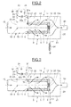
- a filtering or filtration cell referenced 1 as a whole, comprises an intake duct 2, a manifold 4, and a filter unit 3 the intake pipe 2 and the collector 4.
- the filter unit 3 comprises an external electrode 5 of generally cylindrical shape and formed by an agglomerate or a entanglement of metal fibers.
- the electrode 5 forms a passage axial 7 that it surrounds.
- the outer electrode 5 comprises radial front surfaces 8, 9.
- the end face 8 comes into axial contact with a ring 11 of fixing the external electrode 5 on the intake pipe 2.
- the fixing ring 11 comprises an outer surface 12 in contact with a bore 13 of the intake pipe 2.
- the external electrode 5 is open on the side of its front surface 8, so that the central passage 7 communicates with the pipe 2.
- the intake pipe 2 includes an orifice 15 on the opposite side to the outer electrode 5.
- a disc 16 in one electrically conductive material comes to bear axially by a radial surface 17 against the front surface 9 of the electrode, external 5 opposite to the intake pipe 2.
- the disc 16 axially closes the central passage 7 on the opposite side to the intake pipe 2.
- the disc conductor 16 is connected to a zero potential ground by a conductor 14.
- the filter unit 3 also comprises an electrode central 18 in the form of a rod 19 coaxial with the external electrode 5 and one end of which is plugged into an insulating insert 16a mounted in the central part of the insulating disk 16.
- the internal electrode 18 extends axially from its end 20 beyond the crown of fixing 11 being bent to form a radial portion 21 outgoing radially from the intake pipe 2.
- An isolator 23 isolates electrically the wall, the inlet pipe 2 of the electrode 18.
- the radial portion 21 is electrically connected to a high voltage power supply constituted by the low network voltage of the motor vehicle symbolized by reference 24, downstream of which is mounted a low voltage / high voltage converter 32.
- the collector 4 comprises a cylindrical envelope 25 surrounding the portion of the outer electrode 5 located outside the intake duct 2.
- the cylindrical casing 25 extends axially beyond the disc. 16.
- the envelope 25 includes a inner diameter greater than the outer diameter of the electrode external 5, so that there is an empty annular space 26 between the cylindrical envelope 25 and the external electrode 5.
- the collector 4 comprises a radial wall 27 sealing the envelope 25 located on the side of the intake pipe 2.
- the collector 4 is closed on the opposite side to the intake pipe 2 by a radial wall 28 provided with a central opening into which a pipe opens evacuation 30.
- the exhaust gases loaded with soot particles enter in the intake pipe 2 through the inlet port 15, and then penetrate in the central passage 7 of the external electrode 5 which communicates with intake line 2.
- Disc 16 prevents axial passage exhaust gas.
- the exhaust gases are diverted radially and pass through the outer electrode 5 which is permeable to gas.
- the exhaust gases pass into the annular space 26, then circulate in the manifold 4 towards the discharge pipe 30,
- La exhaust pipe 30 can be connected to an exhaust outlet directly, or through different volumes of catalysts for example oxidation type reduction of oxides nitrogen.
- the gases Exhaust charged with particles are mechanically filtered.
- the outer electrode 5 is formed by an agglomerate or a entanglement of wires that form multiple obstacles able to intercept the particles. This filtering process mechanics is intensified by electrostatic filtering resulting from interactions between the entanglement of wires connected to the mass and electrically charged particles.
- the filter cell 1 also has an effect of direct electrostatic filtering of particles-laden gases.
- the external electrode 5 is in fact maintained at a zero potential, the internal electrode 18 being brought to a positive or negative potential.
- the potential difference created between the external and internal electrodes 5 18 induces the presence of an electric field in the axial passage 7. If this electric field has sufficient intensity, in particular at very close neighborhood of the internal electrode 18, there occurs a partial or total ionization of gases, or medium, between internal and external electrodes 18 and 5.
- An ionized gaseous medium comprises free electrons, positive and negative ions. Particles present in the ionized environment combine with electrons or ions forming particles loaded. Similarly, an electronics from an electrode to the other causes collisions between the electrons and the particles that combine to form negatively charged particles.
- the radial circulation of the gases causes the charged particles to the outer electrode 5.
- the charged particles passing through the outer electrode 5 are trapped by interception on the entanglement of metallic threads and by phenomena of electrostatic interactions due to the electric charges carried by said particles.
- the forces of Van Der Walls and the forces of capillarity the particles attached to the metal wires even after they give in their electric charges.
- a capacitor 31 which can be charged by the voltage source 24 after voltage rise by the low voltage / high voltage converter 32, capacitor 31 is mounted between zero potential ground and a fast switch 31a which allows, when the voltage level of the capacitor 31 is above a certain threshold, to directly connect the capacitor 31 for discharge into the external electrode 5 by the connection 33 which passes through the fixing ring 11.
- the switch 22 can be controlled and placed in two positions. In the first position illustrated in dashed lines in the figure 1, the switch 22 places the low converter into communication voltage / high voltage 32 with the central electrode 18 to achieve the filtration of soot particles like, this has been previously Explain.
- a diode 22a is shown between the switch 22 and the capacitor 31 so as to avoid any return of current to the converter 32 during the discharge of the capacitor 31.
- the switch 22 is controlled so as to be placed in the position shown in solid lines in FIG. position, the central electrode 18 is no longer powered, On the contrary, the capacitor 31 gets charged and discharges periodically into a RC circuit whose external electrode 5 is one of the elements resistive.
- Such a capacitor discharge provides heating energy sufficient for the regeneration of the filter cell by elevation temperature.
- the circuit, of regeneration comprises in addition to the capacitor 31, a coil of self-induction 34 mounted in series with the resistive element that constitutes the external electrode 5 and connected to the conductive disk 16 by the connection 14,
- the regeneration circuit includes, the same elements as in the embodiment of the Figure 1.
- the discharge current of the capacitor 31 is brought to through the switch 31a to the electrode 18 by a connection 35 which passes through the wall of the intake pipe 2 by a isolator 36 and is directly connected to the electrode 18.
- the brutal resulting overvoltage applied to the central electrode 18, 19, leads to the development of one or more electric arcs between the rod 19 and the inner surface of the porous electrode 5, on which a large number of trapped particles are accumulated.
- soot particles being strongly exothermic, the injection of a localized energy is then enough to initiate the combustion of all the deposition of the soot particles as soon as that a critical mass of particles is stored on the surface of the electrode 5.
- the development of the electric arc thus allows local warming of the particles of soot accumulated on the surface of the electrode 5, the combustion which in result then propagates to all the particles trapped in the electrode 5, which allows its complete regeneration.
- a complete set of filtration usually includes several elementary cells of filtration. Regeneration can be performed simultaneously on all the elementary cells of filtration by injecting into the entire device the power necessary for such simultaneous regeneration.
- FIG. 4 schematically illustrates means enabling obtaining such a result.
- the internal combustion engine 37 is supplied with air mixture and fuel through the intake ducts 38.
- the gases exhaust are conveyed by the exhaust pipe 39 which is connected to the intake pipe 2 of the filtration cell 1.
- a By-pass valve 40 is mounted at the inlet of the intake pipe 2 and is controlled by a steering block 41 receiving signals from control by the computer 42 of the engine 37.
- the computer receives also by the connection 43 information about the operation instantaneous engine 37.
- the bypass valve 40 is mounted at the entrance a bypass pipe 43, which allows to bypass the passage exhaust through filter cell 1.
- Driving by-pass 43 joins the exhaust pipe 30 downstream of the cell filtering 1.
- a secondary air injection pipe 44 is connected to the intake pipe 2.
- the air is sucked in by blower 45 controlled by the computer 42 to which it is connected through the connection 46.
- the calculator 42 sends the necessary information to the bypass valve 40 through the steering block 41 as well as the injection blower 45 to gradually close the line main exhaust 39 and enrich the flow of gases in the oxygen intake pipe 2 by the flow rate of the blower 45. Simultaneously, the regeneration of the elementary filter cell 1 is triggered by action on the switch 22 shown in the figures preceding.
- the duration of the regeneration is relatively short, so that the untreated exhaust gases are conveyed in bypass driving 43 and schematized by the arrow dashed 47 in minute quantity in relation to the total quantity of exhaust gas discharged by the engine.
- FIG. 5 illustrates an alternative internal bypass.
- a filtering unit 48 comprises a distributor 49 connected to a common inlet 50 which conveys the gases exhaust charged with soot particles.
- the distributor 49 has a plurality of outputs 51, here four in number. Each output 51 is connected to the input of a filter cell 1 of the type described previously.
- a general collector 52 is connected to the outputs of the different filter cells 1.
- a set also includes a control unit, not shown in the figure, to trigger the regeneration phases.
- a bypass valve 53 is mounted at the entrance of the dispenser 49 so as to occupy different positions.
- filter cells 1 are no longer traversed by the gases exhaust, while other filter cells are always crossed by the exhaust gases. It is then possible to trigger the regeneration phase of the two filter cells that are no longer traversed by the exhaust.
- the regeneration of the entire filtering device is therefore only partial during this phase: only part of the set of filter cells is regenerated while the other part of the filtering cells continues to filter.
- the filter cells being regeneration are crossed by a minimum flow of exhaust considering the leaks through the bypass valve 53.
- the gases exhaust systems continue to be filtered by at least part of the filtration device, while the other part is regenerated.
- bypass valve 53 is placed in the position shown in dashed lines in the figure 5 and the other part of the filtration cells is then regenerated.
- the bypass valve 53 can also be placed in position central, so as to allow exhaust gas to pass through the set of filter cells outside the periods of regeneration.
Landscapes
- Engineering & Computer Science (AREA)
- Chemical & Material Sciences (AREA)
- Combustion & Propulsion (AREA)
- Mechanical Engineering (AREA)
- General Engineering & Computer Science (AREA)
- Chemical Kinetics & Catalysis (AREA)
- Physics & Mathematics (AREA)
- Geometry (AREA)
- Processes For Solid Components From Exhaust (AREA)
Applications Claiming Priority (2)
| Application Number | Priority Date | Filing Date | Title |
|---|---|---|---|
| FR0312197A FR2861131B1 (fr) | 2003-10-17 | 2003-10-17 | Systeme de filtration electrostatique de particules de suie des gaz d'echappement d'un moteur a combustion interne et procede de regeneration d'un tel systeme |
| FR0312197 | 2003-10-17 |
Publications (1)
| Publication Number | Publication Date |
|---|---|
| EP1524416A1 true EP1524416A1 (de) | 2005-04-20 |
Family
ID=34355504
Family Applications (1)
| Application Number | Title | Priority Date | Filing Date |
|---|---|---|---|
| EP04300664A Withdrawn EP1524416A1 (de) | 2003-10-17 | 2004-10-08 | Elektrostatisches Filtersystem von Abgasrusspartikeln einer Brennkraftmaschine und Verfahren zur Regenerierung eines solchen Systems |
Country Status (2)
| Country | Link |
|---|---|
| EP (1) | EP1524416A1 (de) |
| FR (1) | FR2861131B1 (de) |
Cited By (6)
| Publication number | Priority date | Publication date | Assignee | Title |
|---|---|---|---|---|
| GB2429417A (en) * | 2005-08-25 | 2007-02-28 | Perkins Engines Co Ltd | Autoselective regenerating particulate filter |
| WO2007116131A1 (fr) * | 2006-04-11 | 2007-10-18 | Renault S.A.S | Dispositif et procede de capture et d’elimination de particules agglomerees issues d’un filtre a particules de vehicule automobile |
| FR2911633A1 (fr) * | 2007-01-22 | 2008-07-25 | Renault Sas | Dispositif de filtre electrostatique pour la capture et la destruction de particules de suie contenues dans les gaz d'echappement d'un moteur a combustion. |
| CN100530536C (zh) * | 2007-03-09 | 2009-08-19 | 台湾积体电路制造股份有限公司 | 承载晶圆的放电系统、静电吸附器与集成电路的制造方法 |
| EP2258931A4 (de) * | 2008-02-25 | 2015-01-14 | Nat Univ Jeju Iacf | Partikelreduktionsgerät für einen dieselmotor |
| CN113366199A (zh) * | 2018-10-22 | 2021-09-07 | 上海必修福企业管理有限公司 | 一种发动机尾气除尘系统和方法 |
Families Citing this family (2)
| Publication number | Priority date | Publication date | Assignee | Title |
|---|---|---|---|---|
| DE102007028134B3 (de) * | 2007-06-19 | 2008-12-18 | Robert Bosch Gmbh | Elektrostatischer Abscheider und Heizungssystem |
| CN113366198B (zh) * | 2018-10-22 | 2023-08-15 | 上海必修福企业管理有限公司 | 一种发动机排放处理系统和方法 |
Citations (6)
| Publication number | Priority date | Publication date | Assignee | Title |
|---|---|---|---|---|
| FR1047054A (fr) * | 1951-01-10 | 1953-12-10 | Sfindex | Filtre électrostatique à ionisateur radio-actif pour l'épuration de l'air d'admission et des gaz d'échappement des moteurs à combustion interne |
| EP0244061A1 (de) * | 1986-02-28 | 1987-11-04 | Porous Element Technology Limited | Einrichtung zur Beseitigung von partikelförmigem Material aus einem Gas |
| DE4021033A1 (de) * | 1990-07-02 | 1992-01-09 | Ibiden Co Ltd | Abgasreinigungsvorrichtung |
| WO1997024516A1 (en) * | 1995-12-29 | 1997-07-10 | Sk Corporation | Device for removing particulate materials from exhaust gas of diesel vehicles |
| US6168689B1 (en) * | 1995-12-28 | 2001-01-02 | Seondo Electric Co., Ltd. | Method and apparatus for cleaning exhaust gas discharged from internal or external combustion engine by using high voltage electric field |
| FR2822893A1 (fr) * | 2001-03-29 | 2002-10-04 | Renault | Systeme de traitement des gaz d'echappement |
Family Cites Families (1)
| Publication number | Priority date | Publication date | Assignee | Title |
|---|---|---|---|---|
| GB2351923A (en) * | 1999-07-12 | 2001-01-17 | Perkins Engines Co Ltd | Self-cleaning particulate filter utilizing electric discharge currents |
-
2003
- 2003-10-17 FR FR0312197A patent/FR2861131B1/fr not_active Expired - Fee Related
-
2004
- 2004-10-08 EP EP04300664A patent/EP1524416A1/de not_active Withdrawn
Patent Citations (6)
| Publication number | Priority date | Publication date | Assignee | Title |
|---|---|---|---|---|
| FR1047054A (fr) * | 1951-01-10 | 1953-12-10 | Sfindex | Filtre électrostatique à ionisateur radio-actif pour l'épuration de l'air d'admission et des gaz d'échappement des moteurs à combustion interne |
| EP0244061A1 (de) * | 1986-02-28 | 1987-11-04 | Porous Element Technology Limited | Einrichtung zur Beseitigung von partikelförmigem Material aus einem Gas |
| DE4021033A1 (de) * | 1990-07-02 | 1992-01-09 | Ibiden Co Ltd | Abgasreinigungsvorrichtung |
| US6168689B1 (en) * | 1995-12-28 | 2001-01-02 | Seondo Electric Co., Ltd. | Method and apparatus for cleaning exhaust gas discharged from internal or external combustion engine by using high voltage electric field |
| WO1997024516A1 (en) * | 1995-12-29 | 1997-07-10 | Sk Corporation | Device for removing particulate materials from exhaust gas of diesel vehicles |
| FR2822893A1 (fr) * | 2001-03-29 | 2002-10-04 | Renault | Systeme de traitement des gaz d'echappement |
Cited By (10)
| Publication number | Priority date | Publication date | Assignee | Title |
|---|---|---|---|---|
| GB2429417A (en) * | 2005-08-25 | 2007-02-28 | Perkins Engines Co Ltd | Autoselective regenerating particulate filter |
| GB2429417B (en) * | 2005-08-25 | 2010-08-11 | Perkins Engines Co Ltd | Autoselective regenerating particulate filter |
| US8388711B2 (en) | 2005-08-25 | 2013-03-05 | Perkins Engine Company Ltd. | Autoselective regenerating particulate filter |
| WO2007116131A1 (fr) * | 2006-04-11 | 2007-10-18 | Renault S.A.S | Dispositif et procede de capture et d’elimination de particules agglomerees issues d’un filtre a particules de vehicule automobile |
| FR2911633A1 (fr) * | 2007-01-22 | 2008-07-25 | Renault Sas | Dispositif de filtre electrostatique pour la capture et la destruction de particules de suie contenues dans les gaz d'echappement d'un moteur a combustion. |
| WO2008107598A1 (fr) * | 2007-01-22 | 2008-09-12 | Renault Sas | Dispositif de filtre electrostatique pour la capture et la destruction de particules de suie contenues dans les gaz d'echappement d'un moteur a combustion |
| CN100530536C (zh) * | 2007-03-09 | 2009-08-19 | 台湾积体电路制造股份有限公司 | 承载晶圆的放电系统、静电吸附器与集成电路的制造方法 |
| EP2258931A4 (de) * | 2008-02-25 | 2015-01-14 | Nat Univ Jeju Iacf | Partikelreduktionsgerät für einen dieselmotor |
| CN113366199A (zh) * | 2018-10-22 | 2021-09-07 | 上海必修福企业管理有限公司 | 一种发动机尾气除尘系统和方法 |
| CN113366199B (zh) * | 2018-10-22 | 2023-10-13 | 上海必修福企业管理有限公司 | 一种发动机尾气除尘系统和方法 |
Also Published As
| Publication number | Publication date |
|---|---|
| FR2861131A1 (fr) | 2005-04-22 |
| FR2861131B1 (fr) | 2008-02-22 |
Similar Documents
| Publication | Publication Date | Title |
|---|---|---|
| EP1212141B1 (de) | Vorrichtung zur behandlung von verbrennungsabgasen einer brennkraftmaschine | |
| FR2951499A1 (fr) | Procede d'evaluation de l'etat d'un capteur de suie dans un vehicule automobile | |
| FR2861131A1 (fr) | Systeme de filtration electrostatique de particules de suie des gaz d'echappement d'un moteur a combustion interne et procede de regeneration d'un tel systeme | |
| EP1506347B1 (de) | Vorrichtung und verfahren zum filtern von mit teilchen beladenen abgasen | |
| FR2911633A1 (fr) | Dispositif de filtre electrostatique pour la capture et la destruction de particules de suie contenues dans les gaz d'echappement d'un moteur a combustion. | |
| EP1528230B1 (de) | Vorrichtung und Verfahren zur Filtrierung von Abgaspartikeln | |
| FR2822893A1 (fr) | Systeme de traitement des gaz d'echappement | |
| EP1541821B1 (de) | Nicht thermischer Plasmareaktor und Kraftfahrzeugabgasanlage mit einem solchen Reaktor | |
| FR2915234A1 (fr) | Systeme de filtration electrostatique pour les gaz d'echappement d'un moteur a combustion interne. | |
| EP2038521B1 (de) | Vorrichtung und verfahren zum auffangen und beseitigen von in abgasen aus einem kraftfahrzeug-verbrennungsmotor enthaltenen partikeln | |
| FR2864143A1 (fr) | Systeme de filtration electrostatique pour les gaz d'echappement d'un moteur a combustion interne | |
| FR2779177A1 (fr) | Dispositif d'echappement a filtre a particules | |
| FR2864141A1 (fr) | Systeme de filtration electrostatique pour les gaz d'echappement d'un moteur a combustion interne | |
| FR2843611A1 (fr) | Electrofiltre a collecte centrale | |
| FR2806125A1 (fr) | Dispositif et procede de regeneration d'un filtre a particules | |
| FR2880062A1 (fr) | Dispositif et procede de capture et d'elimination de particules agglomerees issues d'un filtre a particules de vehicule automobile | |
| EP2417396A1 (de) | Verbesserte vorrichtung zur reinigung von verbrennungsgasen und rauch von einer heizvorrichtung unter verwendung eines festbrennstoffs, insbesondere holz | |
| WO2007116131A1 (fr) | Dispositif et procede de capture et d’elimination de particules agglomerees issues d’un filtre a particules de vehicule automobile | |
| FR3082760A1 (fr) | Dispositif de purification d'un milieu gazeux charge de particules | |
| FR2904656A1 (fr) | Dispositif de traitement de polluants contenus dans des effluents gazeux d'un vehicule automobile et procede associe. | |
| FR2812685A1 (fr) | Dispositif de depollution d'un moteur thermique et groupe de propulsion le comportant | |
| EP1904722A1 (de) | Anordnung zur aufhäufung und sammlung von teilchen aus abgasen eines verbrennungsmotors für ein kraftfahrzeug zur nutzung mit einem hochspannungsnetzteil | |
| FR2880061A1 (fr) | Filtre a particules pour le traitement de gaz d'echappement issus d'un moteur a combustion interne de vehicule automobile et procede de filtrage de gaz d'echappement correspondant | |
| WO2007026087A2 (fr) | Filtre a particules pour le traitement de gaz d'echappement issus d'un moteur a combustion interne de vehicule automobile et procede de filtrage de gaz d'echappement correspondant | |
| EP1574680A1 (de) | Abgasreinigungsanlage für die Brennkraftmachine eines Fahrzeuges und Abgasstrecke mit einer solchen Anlage |
Legal Events
| Date | Code | Title | Description |
|---|---|---|---|
| PUAI | Public reference made under article 153(3) epc to a published international application that has entered the european phase |
Free format text: ORIGINAL CODE: 0009012 |
|
| AK | Designated contracting states |
Kind code of ref document: A1 Designated state(s): AT BE BG CH CY CZ DE DK EE ES FI FR GB GR HU IE IT LI LU MC NL PL PT RO SE SI SK TR |
|
| AX | Request for extension of the european patent |
Extension state: AL HR LT LV MK |
|
| 17P | Request for examination filed |
Effective date: 20050728 |
|
| AKX | Designation fees paid |
Designated state(s): AT BE BG CH CY CZ DE DK EE ES FI FR GB GR HU IE IT LI LU MC NL PL PT RO SE SI SK TR |
|
| STAA | Information on the status of an ep patent application or granted ep patent |
Free format text: STATUS: THE APPLICATION IS DEEMED TO BE WITHDRAWN |
|
| 18D | Application deemed to be withdrawn |
Effective date: 20060530 |