EP1524409A2 - Schaufelrückhaltevorrichtung - Google Patents
Schaufelrückhaltevorrichtung Download PDFInfo
- Publication number
- EP1524409A2 EP1524409A2 EP04003299A EP04003299A EP1524409A2 EP 1524409 A2 EP1524409 A2 EP 1524409A2 EP 04003299 A EP04003299 A EP 04003299A EP 04003299 A EP04003299 A EP 04003299A EP 1524409 A2 EP1524409 A2 EP 1524409A2
- Authority
- EP
- European Patent Office
- Prior art keywords
- retaining ring
- bucket
- restraint device
- blade
- disc
- Prior art date
- Legal status (The legal status is an assumption and is not a legal conclusion. Google has not performed a legal analysis and makes no representation as to the accuracy of the status listed.)
- Granted
Links
Images


Classifications
-
- F—MECHANICAL ENGINEERING; LIGHTING; HEATING; WEAPONS; BLASTING
- F01—MACHINES OR ENGINES IN GENERAL; ENGINE PLANTS IN GENERAL; STEAM ENGINES
- F01D—NON-POSITIVE DISPLACEMENT MACHINES OR ENGINES, e.g. STEAM TURBINES
- F01D5/00—Blades; Blade-carrying members; Heating, heat-insulating, cooling or antivibration means on the blades or the members
- F01D5/30—Fixing blades to rotors; Blade roots ; Blade spacers
- F01D5/32—Locking, e.g. by final locking blades or keys
- F01D5/326—Locking of axial insertion type blades by other means
-
- F—MECHANICAL ENGINEERING; LIGHTING; HEATING; WEAPONS; BLASTING
- F01—MACHINES OR ENGINES IN GENERAL; ENGINE PLANTS IN GENERAL; STEAM ENGINES
- F01D—NON-POSITIVE DISPLACEMENT MACHINES OR ENGINES, e.g. STEAM TURBINES
- F01D5/00—Blades; Blade-carrying members; Heating, heat-insulating, cooling or antivibration means on the blades or the members
- F01D5/30—Fixing blades to rotors; Blade roots ; Blade spacers
- F01D5/3007—Fixing blades to rotors; Blade roots ; Blade spacers of axial insertion type
- F01D5/3015—Fixing blades to rotors; Blade roots ; Blade spacers of axial insertion type with side plates
-
- F—MECHANICAL ENGINEERING; LIGHTING; HEATING; WEAPONS; BLASTING
- F05—INDEXING SCHEMES RELATING TO ENGINES OR PUMPS IN VARIOUS SUBCLASSES OF CLASSES F01-F04
- F05D—INDEXING SCHEME FOR ASPECTS RELATING TO NON-POSITIVE-DISPLACEMENT MACHINES OR ENGINES, GAS-TURBINES OR JET-PROPULSION PLANTS
- F05D2260/00—Function
- F05D2260/30—Retaining components in desired mutual position
-
- F—MECHANICAL ENGINEERING; LIGHTING; HEATING; WEAPONS; BLASTING
- F05—INDEXING SCHEMES RELATING TO ENGINES OR PUMPS IN VARIOUS SUBCLASSES OF CLASSES F01-F04
- F05D—INDEXING SCHEME FOR ASPECTS RELATING TO NON-POSITIVE-DISPLACEMENT MACHINES OR ENGINES, GAS-TURBINES OR JET-PROPULSION PLANTS
- F05D2300/00—Materials; Properties thereof
- F05D2300/50—Intrinsic material properties or characteristics
- F05D2300/501—Elasticity
Definitions
- the invention relates to a blade retention device according to the preamble of the main claim.
- the invention relates to a bucket restraint for the axial fixation of blades on one Disk of a gas turbine, one connected to the blade, Profiled blade foot in one too the profile matching axial groove of the disc is inserted and is axially fixed by means of a split retaining ring, wherein the retaining ring at least partially in a groove of the blade root is included.
- a bucket restraint for example, shows the US 6,234,756 B1.
- the invention is based on the object, a blade retaining device to create the type mentioned, which with a simple structure and simple, cost-effective applicability easy to assemble and a small footprint having.
- the disc with a circumferential annular groove which has an axially inner Has contact surface for the retaining ring and that the retaining ring at least in the axial direction is elastically deformable.
- the blade restraint device according to the invention is characterized through a number of significant benefits.
- the blade restraint device allows the installation also in a multi-stage welded rotor, at which consists of at least one stage of blades, the in the blade root have an outlet opening (micro-turbine).
- the invention enables a favorable introduction of the centrifugal forces below the blade root and thus a low Weight of shovel and disc. This is also the lifetime to extend the entire arrangement.
- the retaining ring can be designed as a sheet metal part, compared to known from the prior art expensive forgings.
- the installation of the blade restraint device according to the invention ensures a high degree of repeatability and thus a repeatability high component reliability.
- the annular groove is provided with at least one insertion opening. Through this insertion, the retaining ring can be easily and without damage be inserted or removed.
- the retaining ring of two or more Layers of a metallic material consisting of a End of the retaining ring are connected together. This will significantly increases the elasticity of the retaining ring. this in turn causes the retaining ring to be inserted into the groove can and remains in this without deformation.
- the retaining ring with a Anti-rotation is provided to a hiking of the retaining ring to avoid in the circumferential direction.
- the rotation is more preferred Way in the form of a radially directed approach of the Retaining ring formed, the preferred manner at one end the retaining ring is provided.
- the retaining ring can be inserted and be fixed by means of the rotation.
- the retaining ring is a strip-shaped Cross section has. By such a rectangular Cross-section is sufficient penetration of the retaining ring in ensures the groove of the blade root or the disc.
- the retaining ring according to the invention in scope in several segments be divided, for example, in six segments.
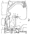
- Fig. 1 shows a simplified representation of a rotatably mounted Disc 2 of a gas turbine engine, at which several Shovels 1 are attached. Adjacent stator blades are provided with the reference numeral 10. Incidentally, to the general structure referred to the prior art reference so that its description can be omitted.
- the lower portions of the blade roots 3 are each with a Circumferential groove 6 provided.
- the disc 2 has, as most clearly seen in Fig. 1 is, an annular groove 7, which opens radially outward is and has a plant leg 11, as can be seen from FIG. 1 results.
- the blade restraining device according to the invention further comprises a divided into individual segments retaining ring 4, the at its free end with a radially outward facing Approach 9 is provided (see in particular Fig. 6).
- the annular groove 7 has one or more insertion openings 8, realized by an interruption of the plant leg 11 are. Through these insertion openings 8, it is possible in Axial direction elastically deformable retaining ring 4, as can be seen from the illustrations of FIGS. 2 and 3 results.
- the insertion opening 8 consists, as mentioned, of a recess in the lower Annular groove 7.
Landscapes
- Engineering & Computer Science (AREA)
- Mechanical Engineering (AREA)
- General Engineering & Computer Science (AREA)
- Turbine Rotor Nozzle Sealing (AREA)
- Structures Of Non-Positive Displacement Pumps (AREA)
Abstract
Description
- Fig. 1
- eine schematische Teil-Seiten-Schnittansicht der Einbausituation der erfindungsgemäßen Schaufelrückhaltevorrichtung,
- Fig. 2
- eine vergrößerte Teil-Ansicht in radialer Richtung von außen auf den Montagevorgang des Halterings,
- Fig. 3
- eine vergrößerte Darstellung der Ansicht gemäß Fig. 2,
- Fig. 4
- eine axiale Teil-Ansicht der erfindungsgemäßen Schaufelrückhaltevorrichtung im montierten Zustand,
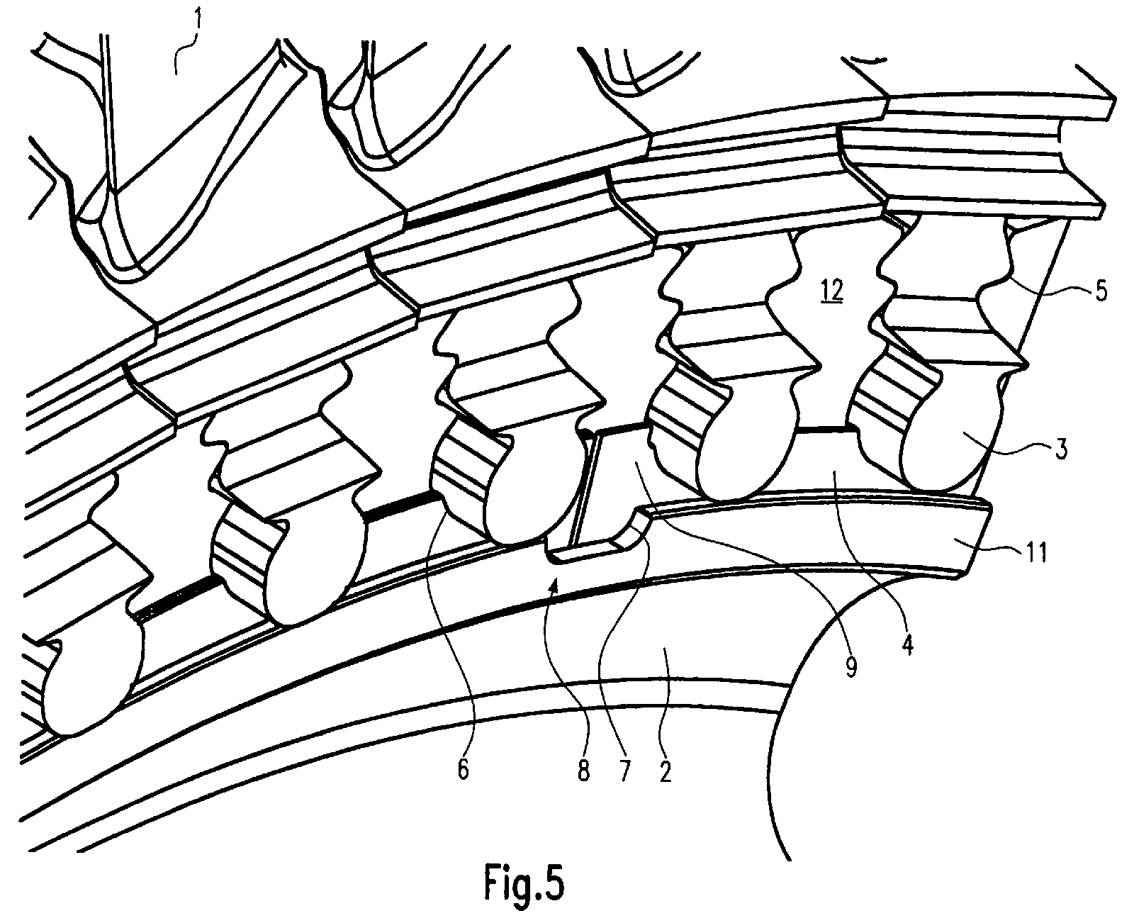
- Fig. 5
- eine perspektivische Teil-Ansicht der in Fig. 4 gezeigten Situation, und
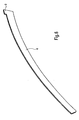
- Fig. 6
- eine perspektivische Ansicht eines erfindungsgemäßen Halterings.
- 1
- Schaufel
- 2
- Scheibe
- 3
- Schaufelfuß
- 4
- Halterung
- 5
- Axialnut von 2
- 6
- Nut von 3
- 7
- Ringnut
- 8
- Einführöffnung
- 9
- Ansatz
- 10
- Statorschaufel
- 11
- Anlageschenkel
- 12
- Scheibenfinger
Claims (9)
- Schaufelrückhaltevorrichtung (1) für die axiale Fixierung von Schaufeln (1) an einer Scheibe (2), wobei ein mit der Schaufel (1) verbundener, mit einem Profil versehener Schaufelfuß (3) in eine zu dem Profil passende Axialnut (5) der Scheibe (2) eingeschoben ist und mittels eines geteilten Halterings (4) axial fixiert ist, wobei der Haltering (4) zumindest teilweise in einer Nut (6) des Schaufelfußes (3) aufgenommen ist, dadurch gekennzeichnet, dass die Scheibe (2) mit einer umlaufenden Ringnut (7) versehen ist, welche eine radial innere Anlagefläche für den Haltering (4) aufweist und dass der Haltering (4) zumindest in axialer Richtung elastisch verformbar ist.
- Schaufelrückhaltevorrichtung nach Anspruch 1, dadurch gekennzeichnet, dass die Ringnut (7) mit zumindest einer Einführöffnung (8) versehen ist.
- Schaufelrückhaltevorrichtung nach Anspruch 1 oder 2, dadurch gekennzeichnet, dass der Haltering (4) aus zwei oder mehr Lagen besteht, welche an einem Ende des Halterings (4) miteinander verbunden sind.
- Schaufelrückhaltevorrichtung nach einem der Ansprüche 1 bis 3, dadurch gekennzeichnet, dass eine Verdrehsicherung für den Haltering (4) vorgesehen ist.
- Schaufelrückhaltevorrichtung nach Anspruch 4, dadurch gekennzeichnet, dass die Verdrehsicherung einen radial gerichteten Ansatz (9) des Halterings (4) umfasst.
- Schaufelrückhaltevorrichtung nach einem der Ansprüche 4 oder 5, dadurch gekennzeichnet, dass die Verdrehsicherung an einem Ende des Halterings (4) ausgebildet ist.
- Schaufelrückhaltevorrichtung nach einem der Ansprüche 1 bis 6, dadurch gekennzeichnet, dass der Haltering (4) einen streifenförmigen Querschnitt hat.
- Schaufelrückhaltevorrichtung nach einem der Ansprüche 1 bis 7, dadurch gekennzeichnet, dass der Haltering (4) in Umfangsrichtung in Segmente geteilt ist.
- Schaufelrückhaltevorrichtung nach Anspruch 8, dadurch gekennzeichnet, dass sechs Segmente vorgesehen sind.
Applications Claiming Priority (2)
| Application Number | Priority Date | Filing Date | Title |
|---|---|---|---|
| DE10348198A DE10348198A1 (de) | 2003-10-16 | 2003-10-16 | Schaufelrückhaltevorrichtung |
| DE10348198 | 2003-10-16 |
Publications (3)
| Publication Number | Publication Date |
|---|---|
| EP1524409A2 true EP1524409A2 (de) | 2005-04-20 |
| EP1524409A3 EP1524409A3 (de) | 2007-01-24 |
| EP1524409B1 EP1524409B1 (de) | 2011-08-10 |
Family
ID=34353443
Family Applications (1)
| Application Number | Title | Priority Date | Filing Date |
|---|---|---|---|
| EP04003299A Expired - Lifetime EP1524409B1 (de) | 2003-10-16 | 2004-02-13 | Schaufelrückhaltevorrichtung |
Country Status (3)
| Country | Link |
|---|---|
| US (1) | US7244105B2 (de) |
| EP (1) | EP1524409B1 (de) |
| DE (1) | DE10348198A1 (de) |
Cited By (1)
| Publication number | Priority date | Publication date | Assignee | Title |
|---|---|---|---|---|
| RU2330163C1 (ru) * | 2006-11-01 | 2008-07-27 | Открытое акционерное общество "Силовые машины-ЗТЛ, ЛМЗ, Электросила, Энергомашэкспорт" (ОАО "Силовые машины") | Рабочее колесо газовой турбины |
Families Citing this family (14)
| Publication number | Priority date | Publication date | Assignee | Title |
|---|---|---|---|---|
| DE102004016977B4 (de) * | 2004-04-07 | 2006-11-23 | Mtu Aero Engines Gmbh | Rotor für eine Turbomaschine |
| CN101258305B (zh) * | 2005-09-07 | 2011-06-15 | 西门子公司 | 用于对转子中的动叶片进行轴向固定的装置、用于一种这样的装置的密封件以及一种这样的装置的应用 |
| DE102006054154B4 (de) * | 2006-11-16 | 2014-03-13 | Man Diesel & Turbo Se | Abgasturbolader |
| US8221083B2 (en) | 2008-04-15 | 2012-07-17 | United Technologies Corporation | Asymmetrical rotor blade fir-tree attachment |
| US8162615B2 (en) * | 2009-03-17 | 2012-04-24 | United Technologies Corporation | Split disk assembly for a gas turbine engine |
| FR2951224B1 (fr) * | 2009-10-13 | 2011-12-09 | Turbomeca | Roue de turbine equipee d'un jonc de retenue axiale verrouillant des pales par rapport a un disque |
| US9051845B2 (en) | 2012-01-05 | 2015-06-09 | General Electric Company | System for axial retention of rotating segments of a turbine |
| JP5675674B2 (ja) * | 2012-02-29 | 2015-02-25 | 三菱重工業株式会社 | タービン動翼の抜け止め構造およびこれを備えた回転機械 |
| US9140136B2 (en) | 2012-05-31 | 2015-09-22 | United Technologies Corporation | Stress-relieved wire seal assembly for gas turbine engines |
| US9366145B2 (en) | 2012-08-24 | 2016-06-14 | United Technologies Corporation | Turbine engine rotor assembly |
| US9790803B2 (en) | 2013-03-08 | 2017-10-17 | United Technologies Corporation | Double split blade lock ring |
| US10724384B2 (en) * | 2016-09-01 | 2020-07-28 | Raytheon Technologies Corporation | Intermittent tab configuration for retaining ring retention |
| US10876429B2 (en) | 2019-03-21 | 2020-12-29 | Pratt & Whitney Canada Corp. | Shroud segment assembly intersegment end gaps control |
| FR3150239B1 (fr) * | 2023-06-23 | 2025-06-27 | Safran Aircraft Engines | Ensemble comprenant un segment d’arret axial et un outil de deverrouillage dudit segment d’arret axial et procede de deverrouillage d’un segment d’arret axial domaine technique de l’invention |
Family Cites Families (5)
| Publication number | Priority date | Publication date | Assignee | Title |
|---|---|---|---|---|
| DE1830030U (de) * | 1961-03-04 | 1961-04-27 | Gen Electric | Sicherung der schaufeln in den laeufern von turbinen, kompressoren od. dgl. |
| US3656865A (en) * | 1970-07-21 | 1972-04-18 | Gen Motors Corp | Rotor blade retainer |
| FR2603333B1 (fr) * | 1986-09-03 | 1990-07-20 | Snecma | Rotor de turbomachine comportant un moyen de verrouillage axial et d'etancheite d'aubes montees dans des brochages axiaux du disque et procede de montage |
| GB2258273B (en) * | 1991-08-02 | 1994-08-10 | Ruston Gas Turbines Ltd | Rotor blade locking arrangement |
| GB9517369D0 (en) * | 1995-08-24 | 1995-10-25 | Rolls Royce Plc | Bladed rotor |
-
2003
- 2003-10-16 DE DE10348198A patent/DE10348198A1/de not_active Withdrawn
-
2004
- 2004-02-13 EP EP04003299A patent/EP1524409B1/de not_active Expired - Lifetime
- 2004-05-11 US US10/842,448 patent/US7244105B2/en not_active Expired - Fee Related
Cited By (1)
| Publication number | Priority date | Publication date | Assignee | Title |
|---|---|---|---|---|
| RU2330163C1 (ru) * | 2006-11-01 | 2008-07-27 | Открытое акционерное общество "Силовые машины-ЗТЛ, ЛМЗ, Электросила, Энергомашэкспорт" (ОАО "Силовые машины") | Рабочее колесо газовой турбины |
Also Published As
| Publication number | Publication date |
|---|---|
| US20050084376A1 (en) | 2005-04-21 |
| EP1524409A3 (de) | 2007-01-24 |
| DE10348198A1 (de) | 2005-05-12 |
| EP1524409B1 (de) | 2011-08-10 |
| US7244105B2 (en) | 2007-07-17 |
Similar Documents
| Publication | Publication Date | Title |
|---|---|---|
| EP1457640B1 (de) | Wirbelgleichrichter in Röhrenbauweise mit Haltering für Gasturbinen | |
| EP1714006B1 (de) | Dämpfungsanordnung für leitschaufeln | |
| EP0906514B1 (de) | Rotor für eine turbomaschine mit in nuten anbringbaren schaufeln sowie schaufel für einen rotor | |
| DE60203563T2 (de) | Zentripetale Abblasvorrichtung | |
| EP1524409B1 (de) | Schaufelrückhaltevorrichtung | |
| DE69515508T2 (de) | Befestigung für die schaufel einer gasturbine | |
| EP1092081B1 (de) | Rotor für eine turbomaschine | |
| WO2007028703A1 (de) | Anordnung zur axialsicherung von laufschaufeln in einem rotor sowie verwendung | |
| EP3999717B1 (de) | Zwischenelement für eine schaufel-rotorscheiben-verbindung bei einem rotor einer strömungsmaschine, rotor für eine strömungsmaschine und strömungsmaschine | |
| EP2478186B1 (de) | Rotor einer Turbomaschine | |
| EP1650405B1 (de) | Rotor einer Turbomaschine, insbesondere Gasturbinenrotor | |
| DE102015116935A1 (de) | Sicherungsvorrichtung zur axialen Sicherung einer Laufschaufel und Rotorvorrichtung mit einer derartigen Sicherungsvorrichtung | |
| EP1620632B1 (de) | Speichenzentrierte bürstendichtungsanordnung in einer gasturbine | |
| EP1584793B1 (de) | Turbinenschaufelarretiervorrichtung zur axialen Sicherung einer Turbinenschaufel | |
| EP3379037B1 (de) | Dichtung am innenring eines leitschaufelkranzes | |
| EP3176386B1 (de) | Innenringsystem, zugehöriger innenring, zwichengehäuse und strömungsmaschine | |
| EP3287608A1 (de) | Innenring für einen leitschaufelkranz einer strömungsmaschine | |
| EP3309359B1 (de) | Laufschaufelbaugruppe für ein triebwerk | |
| EP3875736B1 (de) | Dichtungsvorrichtung für eine strömungsmaschine, dichtungsträgerringelement für eine dichtungsvorrichtung und strömungsmaschine | |
| DE19823157A1 (de) | Einrichtung zur Befestigung der Laufschaufeln axial durchströmter Turbomaschinen | |
| EP1698758B1 (de) | Axial getrennter Rotor-Schluss | |
| EP1350924B1 (de) | Statorschaufelsegmentbefestigung für eine Gasturbine | |
| EP1657404B1 (de) | Rotor einer Turbomaschine, insbesondere Gasturbinenrotor | |
| WO2005017320A1 (de) | Rotor für eine gasturbine sowie gasturbine | |
| EP1957755A1 (de) | Turbomaschine mit axialer laufschaufelsicherung |
Legal Events
| Date | Code | Title | Description |
|---|---|---|---|
| PUAI | Public reference made under article 153(3) epc to a published international application that has entered the european phase |
Free format text: ORIGINAL CODE: 0009012 |
|
| AK | Designated contracting states |
Kind code of ref document: A2 Designated state(s): AT BE BG CH CY CZ DE DK EE ES FI FR GB GR HU IE IT LI LU MC NL PT RO SE SI SK TR |
|
| AX | Request for extension of the european patent |
Extension state: AL LT LV MK |
|
| PUAL | Search report despatched |
Free format text: ORIGINAL CODE: 0009013 |
|
| AK | Designated contracting states |
Kind code of ref document: A3 Designated state(s): AT BE BG CH CY CZ DE DK EE ES FI FR GB GR HU IE IT LI LU MC NL PT RO SE SI SK TR |
|
| AX | Request for extension of the european patent |
Extension state: AL LT LV MK |
|
| RIN1 | Information on inventor provided before grant (corrected) |
Inventor name: MOELLER, TIM |
|
| 17P | Request for examination filed |
Effective date: 20070403 |
|
| 17Q | First examination report despatched |
Effective date: 20070604 |
|
| AKX | Designation fees paid |
Designated state(s): DE FR GB |
|
| GRAP | Despatch of communication of intention to grant a patent |
Free format text: ORIGINAL CODE: EPIDOSNIGR1 |
|
| GRAS | Grant fee paid |
Free format text: ORIGINAL CODE: EPIDOSNIGR3 |
|
| GRAA | (expected) grant |
Free format text: ORIGINAL CODE: 0009210 |
|
| AK | Designated contracting states |
Kind code of ref document: B1 Designated state(s): DE FR GB |
|
| REG | Reference to a national code |
Ref country code: GB Ref legal event code: FG4D Free format text: NOT ENGLISH |
|
| REG | Reference to a national code |
Ref country code: DE Ref legal event code: R096 Ref document number: 502004012768 Country of ref document: DE Effective date: 20111013 |
|
| PLBE | No opposition filed within time limit |
Free format text: ORIGINAL CODE: 0009261 |
|
| STAA | Information on the status of an ep patent application or granted ep patent |
Free format text: STATUS: NO OPPOSITION FILED WITHIN TIME LIMIT |
|
| 26N | No opposition filed |
Effective date: 20120511 |
|
| REG | Reference to a national code |
Ref country code: DE Ref legal event code: R097 Ref document number: 502004012768 Country of ref document: DE Effective date: 20120511 |
|
| REG | Reference to a national code |
Ref country code: DE Ref legal event code: R082 Ref document number: 502004012768 Country of ref document: DE Representative=s name: HOEFER & PARTNER, DE |
|
| REG | Reference to a national code |
Ref country code: DE Ref legal event code: R082 Ref document number: 502004012768 Country of ref document: DE Representative=s name: HOEFER & PARTNER, DE Effective date: 20130402 Ref country code: DE Ref legal event code: R081 Ref document number: 502004012768 Country of ref document: DE Owner name: ROLLS-ROYCE DEUTSCHLAND LTD & CO KG, DE Free format text: FORMER OWNER: ROLLS-ROYCE DEUTSCHLAND LTD & CO KG, 15827 BLANKENFELDE, DE Effective date: 20130402 Ref country code: DE Ref legal event code: R081 Ref document number: 502004012768 Country of ref document: DE Owner name: ROLLS-ROYCE DEUTSCHLAND LTD & CO KG, DE Free format text: FORMER OWNER: ROLLS-ROYCE DEUTSCHLAND LTD & CO KG, 15827 BLANKENFELDE, DE Effective date: 20110819 Ref country code: DE Ref legal event code: R082 Ref document number: 502004012768 Country of ref document: DE Representative=s name: HOEFER & PARTNER PATENTANWAELTE MBB, DE Effective date: 20130402 |
|
| PGFP | Annual fee paid to national office [announced via postgrant information from national office to epo] |
Ref country code: FR Payment date: 20140317 Year of fee payment: 11 |
|
| PGFP | Annual fee paid to national office [announced via postgrant information from national office to epo] |
Ref country code: GB Payment date: 20140227 Year of fee payment: 11 |
|
| PGFP | Annual fee paid to national office [announced via postgrant information from national office to epo] |
Ref country code: DE Payment date: 20140327 Year of fee payment: 11 |
|
| REG | Reference to a national code |
Ref country code: DE Ref legal event code: R119 Ref document number: 502004012768 Country of ref document: DE |
|
| GBPC | Gb: european patent ceased through non-payment of renewal fee |
Effective date: 20150213 |
|
| REG | Reference to a national code |
Ref country code: FR Ref legal event code: ST Effective date: 20151030 |
|
| PG25 | Lapsed in a contracting state [announced via postgrant information from national office to epo] |
Ref country code: DE Free format text: LAPSE BECAUSE OF NON-PAYMENT OF DUE FEES Effective date: 20150901 Ref country code: GB Free format text: LAPSE BECAUSE OF NON-PAYMENT OF DUE FEES Effective date: 20150213 |
|
| PG25 | Lapsed in a contracting state [announced via postgrant information from national office to epo] |
Ref country code: FR Free format text: LAPSE BECAUSE OF NON-PAYMENT OF DUE FEES Effective date: 20150302 |