EP1524223B1 - Adjustable vacuum assembly for a roll - Google Patents
Adjustable vacuum assembly for a roll Download PDFInfo
- Publication number
- EP1524223B1 EP1524223B1 EP04256392A EP04256392A EP1524223B1 EP 1524223 B1 EP1524223 B1 EP 1524223B1 EP 04256392 A EP04256392 A EP 04256392A EP 04256392 A EP04256392 A EP 04256392A EP 1524223 B1 EP1524223 B1 EP 1524223B1
- Authority
- EP
- European Patent Office
- Prior art keywords
- roll
- vacuum
- slug
- internal cavity
- spool
- Prior art date
- Legal status (The legal status is an assumption and is not a legal conclusion. Google has not performed a legal analysis and makes no representation as to the accuracy of the status listed.)
- Expired - Lifetime
Links
Images




Classifications
-
- B—PERFORMING OPERATIONS; TRANSPORTING
- B65—CONVEYING; PACKING; STORING; HANDLING THIN OR FILAMENTARY MATERIAL
- B65H—HANDLING THIN OR FILAMENTARY MATERIAL, e.g. SHEETS, WEBS, CABLES
- B65H5/00—Feeding articles separated from piles; Feeding articles to machines
- B65H5/22—Feeding articles separated from piles; Feeding articles to machines by air-blast or suction device
- B65H5/222—Feeding articles separated from piles; Feeding articles to machines by air-blast or suction device by suction devices
- B65H5/226—Feeding articles separated from piles; Feeding articles to machines by air-blast or suction device by suction devices by suction rollers
-
- B—PERFORMING OPERATIONS; TRANSPORTING
- B65—CONVEYING; PACKING; STORING; HANDLING THIN OR FILAMENTARY MATERIAL
- B65H—HANDLING THIN OR FILAMENTARY MATERIAL, e.g. SHEETS, WEBS, CABLES
- B65H45/00—Folding thin material
- B65H45/12—Folding articles or webs with application of pressure to define or form crease lines
- B65H45/16—Rotary folders
- B65H45/162—Rotary folders with folding jaw cylinders
-
- B—PERFORMING OPERATIONS; TRANSPORTING
- B65—CONVEYING; PACKING; STORING; HANDLING THIN OR FILAMENTARY MATERIAL
- B65H—HANDLING THIN OR FILAMENTARY MATERIAL, e.g. SHEETS, WEBS, CABLES
- B65H45/00—Folding thin material
- B65H45/12—Folding articles or webs with application of pressure to define or form crease lines
- B65H45/24—Interfolding sheets, e.g. cigarette or toilet papers
-
- B—PERFORMING OPERATIONS; TRANSPORTING
- B65—CONVEYING; PACKING; STORING; HANDLING THIN OR FILAMENTARY MATERIAL
- B65H—HANDLING THIN OR FILAMENTARY MATERIAL, e.g. SHEETS, WEBS, CABLES
- B65H2406/00—Means using fluid
- B65H2406/30—Suction means
- B65H2406/36—Means for producing, distributing or controlling suction
- B65H2406/361—Means for producing, distributing or controlling suction distributing vacuum from stationary element to movable element
- B65H2406/3614—Means for producing, distributing or controlling suction distributing vacuum from stationary element to movable element involving a shoe in sliding contact with an inner section of the periphery of a rotating element
Definitions
- This invention generally relates to an interfolding machine for interfolding sheet or web material, and more specifically, to an interfolding machine that includes an assembly that provides on the fly adjustment for an on/off position of a vacuum for selectively holding and releasing of the sheet or web material on certain rolls incorporated in the interfolding machine.
- Interfolding of sheet material is frequently performed using a series of rolls that cooperate to sever web material into sheets, overlap the sheets, and interfold the overlapped sheets to form an interfolded stack of sheets.
- Certain of the rolls include a vacuum system having vacuum ports on the outer surface of the roll, which are selectively supplied with vacuum to hold and release the sheets during rotation of the roll.
- a roll is internally drilled to route air flow from the roll surface to the roll sides.
- Stationary side valves are spring loaded against the roll sides to encapsulate the vacuum ports on the rolls sides.
- Each side valve is in the form of a plate which has a rectangular cross section, circular cavity machined into the side of the valve face, which bears against the roll side.
- the valve cavity matches the ports in the roll side.
- the valve cavity intersects a perpendicular supply port that interfaces the valve with a vacuum supply system. Partial segment slugs are positioned in the valve cavity, so as to correspond to vacuum on/off points in rotation of the roll. The slugs are held in position with bolts through slots in the outer sides of the valve.
- US 6539829 upon which the pre-characterising clause of claim 1 is based, discloses a vacuum assembly for a rotating roll for handling sheet or web material, the rotating roll including a plurality of holes in an outer surface and passages that open onto a face of the roll that are in communication with the plurality of holes, wherein the holes are adapted to communicate a vacuum for holding and releasing the sheet or web material, comprising: a rotary union located in line with and outwardly of the roll face, wherein the rotary union defines an internal cavity that is supplied with vacuum from a vacuum source; and a valve assembly positioned axially between a journal of the roll and the rotary union, wherein the valve assembly includes a non-linear passage arrangement configured to communicate vacuum throughout a portion of the rotation of the roll from the internal cavity of the vacuum manifold to the passages that open onto the roll face. Accordingly, the central supply of the vacuum limits the available vacuum volume, and the bends and turns in the vacuum supply path function to hinder the transfer of negative air pressure to the surfaces of the roll
- a vacuum assembly for a rotating roll for handling sheet or web material including a plurality of holes in an outer surface and passages that open onto a face of the roll that are in communication with the plurality of holes, wherein the holes are adapted to communicate a vacuum for holding and releasing the sheet or web material, comprising: a vacuum manifold located in line with and outwardly of the roll face, wherein the vacuum manifold defines an internal cavity that is supplied with vacuum from a vacuum source; and a valve assembly positioned between the roll face and the vacuum manifold, wherein the valve assembly includes a porting arrangement configured to communicate vacuum throughout a portion of the rotation of the roll from the internal cavity of the vacuum manifold to the passages that open onto the roll face; said valve assembly including an intake region that communicates vacuum from the internal cavity of the vacuum manifold to the passages that open onto the roll face, and further including an adjustment arrangement for adjusting the location of the intake region and the position of a pair of
- the valve assembly includes an outer slug plate; an inner slug plate; a spool mounted to the inner slug plate, the spool having an opening; and a cover coupled to the spool, wherein the cover and the spool cooperate to define the internal cavity, wherein the internal cavity is in communication with the spool opening; wherein the outer slug plate and the inner slug plate are rotatably adjustable relative to the spool and to one another; and wherein the outer slug plate and the inner slug plate are configured to regulate the supply of vacuum from the internal cavity to the holes of the rotating roll.
- the outer slug and the inner slug are rotatably adjustable relative to the spool and relative to one another, to control the on/off positions at which suction or vacuum is supplied to the roll surface.
- the slugs are advantageously configured to be adjustable while the roll is rotating, to provide on-the-fly adjustment of the on/off positions.
- an interfolding machine for handling and interfolding sheet or web material comprising the vacuum assembly and rotating roll according to the first aspect of the invention
- a method of regulating the supply of suction from a suction source to holes at a surface of a rotating roll and through roll ports in a side face of the rotating roll comprising the acts of: supplying vacuum from a vacuum source to a vacuum manifold located in line with and outwardly of the roll face, wherein the vacuum manifold defines an internal cavity that is supplied with vacuum; and communicating vacuum throughout a portion of the rotation of the roll from the internal cavity of the vacuum manifold to the roll ports via a valve assembly positioned between the roll face and the vacuum manifold, wherein the valve assembly includes a porting arrangement through which vacuum is supplied from the internal cavity to the roll ports; said act of communicating vacuum throughout a portion of the rotation of the roll from the internal cavity of the vacuum manifold to the roll ports being carried out by supplying the vacuum through an intake region of the valve assembly that communicates vacuum from the internal cavity of the vacuum manifold to the roll ports, and further comprising the act of adjusting the
- an interfolding machine 25 is operable to convert a web of material 30 into a stack of interfolded sheets of material shown at 32.
- Interfolding machine 25 generally includes a first pull roll 35 and a second pull roll 40 that receive the web of material 30 along a path (illustrated by an arrow 42 in FIG. 2) from a supply roll (not shown) into the interfolding machine 20.
- the first and second pull rolls 35 and 40 define a nip through which the web of material 30 passes, and function to unwind the web of material 30 and feed the web of material 30 in a path (illustrated by an arrow 44 in FIG. 2) toward a nip defined between second pull roll 40 and a bed roll 45.
- the web of material 30 is then advanced by bed roll 45 toward a knife roll 50.
- the knife roll 50 cuts the web of material 30 into sheets, each of which has a predetermined length
- the bed roll 45 carries the sheets of material along a path (illustrated by arrow 52 in FIG. 2) toward and through a nip defined between bed roll 45 and a retard roll 55, which rotates at a slower speed of rotation than the bed roll 45.
- the retard roll 55 cooperates with a nip roller assembly 60 (FIG. 2) to form an overlap between the consecutive sheets of material.
- the retard roll 55 carries the overlapped sheets of material along a path (illustrated by arrow 68 in FIG. 2) to a lap roll 65.
- the lap roll 65 works in combination with a count roll 75 to eliminate the overlap between adjacent sheets of material at a predetermined sheet count, so as to create a separation in the stack 32 of interfolded sheets discharged from the interfolding machine 25.
- the lap roll 65 carries the overlapped sheets 30 along a path (illustrated by arrow 78 in FIG. 2) toward a nip defined between a first assist roll 80 and an adjacent second assist roll 85.
- the first and second assist rolls 80 and 85 feed the sheets of the material to a nip defined between a first folding roll 90 and a second folding roll 95.
- the first and second folding rolls 90 and 95 generally rotate in opposite directions (illustrated by arrows 96 and 98, respectively, in FIG. 2) to receive the overlapped sheets of material 30 therebetween.
- the periphery of the first folding roll 90 generally includes a series of the gripper assemblies 100 and a series of tucker assemblies 105 uniformly and alternately spaced to interact with a series of gripper assemblies 100 and tucker assemblies 105 of the adjacent second folding roll 95.
- the series of alternately spaced gripper assemblies 100 and tucker assemblies 105 of the first and second folding rolls 90 and 95 interact to grip, carry, and release the sheets of material in a desired manner so as to form the desired interfolded relationship in the sheets of material and to form stack 32 of interfolded sheets.
- the folding rolls 90 and 95 may be driven by a drive system 110 having a drive belt assembly 115 (FIG. 1).
- the stack 32 of interfolded sheets is discharged from between the first and second folding rolls 90 and 95 in a generally vertically-aligned fashion.
- the stack 32 of interfolded sheets may be supplied to a discharge and transfer system (not shown), which guides and conveys the stack 32 from the generally vertically-aligned orientation at the discharge of the interfolding machine 25 to a generally horizontally-aligned movement.
- a discharge and transfer system is described in U.S. Patent No. 6,712,746 entitled “Discharge and Transfer System for Interfolded Sheets," filed May 5, 2000.
- FIGS. 3-6 illustrate one embodiment of a vacuum valve assembly 20 in accordance with the present invention, for supplying a suction or vacuum to a surface of a rotating roll 118.
- the rotating roll 118 can be, but is not limited to, any of previously described rolls that include a suction feature for holding a sheet or web to the roll, e.g., bed roll 45, retard roll 55, lap roll 65, etc.
- the roll 118 is drilled to internally route the fluid flow (e.g., suction or vacuum pressure) from holes 119 at a roll surface 120 to side ports 121 at a roll side or face 122.
- the vacuum valve assembly 20 is located between a machine frame 124 and the roll face 122, and is generally held stationary and piloted on a roll journal 126 at each end of the rotating roll 118.
- a gear drive assembly 128 and/or an end coupling assembly 129 is engaged with the end of roll journal 126 externally of frame 124, for imparting rotation to roll 118 in a manner as is known.
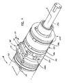
- the valve assembly 20 generally includes an outer adjustable slug plate 130, a pilot ring 135, an inner adjustable slug plate 140, a spool 145, and a cover/manifold 150.
- the outer and inner slug plates 130 and 140 are rotatably adjustable relative to the spool 145 as well as relative to each other.
- outer slug plate 130 generally includes a ring shaped body 155 having a gap 160 and an inner extension 165.
- the size of the gap 160 can vary.
- the inner extension 165 generally extends radially inward from an inner arcuate surface 170 of the ring-shaped body 155.
- the size and location of the extension 165 can vary.
- the outer slug plate 130 further includes one or more lubrication passages or openings 175 extending from an exterior surface, shown at 180, to the inner surface 170 of the outer slug plate 130.
- the pilot ring 135 couples or attaches the outer slug plate 130 to the inner slug plate 140 such that the outer slug plate 130 is rotatable relative to the inner slug plate 140.
- Fasteners such as screws 181 extend into threaded passages in inner slug plate 140 and into engagement with pilot ring 135, to prevent rotation of pilot ring 135 relative to inner slug plate 140.
- the pilot ring 135 generally maintains the concentricity between the outer 130 and the inner 140 slug plates.
- outer slug plate 130 and inner slug plate 140 are formed with facing grooves 182, 183, respectively, within which pilot ring 135 is engaged, to enable relative rotation between outer slug plate 130 and inner slug plate 140.
- a block 185 is mounted to the external surface of outer slug plate 130.
- a link 187 is mounted to block 185, and is used to control the rotational position of outer slug plate 130.
- a link 188 is coupled to an arm 189, which is secured within the open end of inner slug plate 140 defined by opening 190, and is used to control the rotational position of inner slug plate 140.
- the links 187 and 188 are used to radially position the outer slug plate 130 relative to the inner slug plate 140, to allow an operator to make adjustments to the ON/OFF operation of the vacuum valve assembly 20 while the rotating roll 118 is moving and the machine 25 is running.
- the wear parts, including the outer slug plate 130 and the inner slug plate 140 are configured and mounted such that they can be readily removed from and re-installed on the interfolding machinery 20 for service or replacement.
- inner slug plate 140 establishes communication between the interior of the vacuum valve assembly 20 and the roll face 122 of the rotating roll 118.
- inner slug plate 140 includes a U-shaped opening 190 and a separate arcuate, oval opening 195.
- the inner slug plate 140 includes an inner extension section 197, through which opening 195 extends, and inner extension section 197 overlaps outer slug plat 130.
- the inner slug plate 140 includes a groove 198 that faces the adjacent end surface of spool 145.
- a guide ring 199 is formed on the facing end surface of spool 145, and is received within groove 198, to locate inner slug plate 140 on spool 145 and to guide rotational movement of inner slug plate 140 relative to spool 145.
- inner slug plate 140 is rotatable relative to the outer slug plate 130 and the spool 145, to adjust the positions of openings 190 and 195.
- the size and location of the opening 195 generally aligns with the dimensions of the extension 165 of the outer slug plate 130. That is, outer slug plate extension 165 is configured such that its inner end is located closely adjacent the outer surface defined by inner extension section 197 of inner slug plate 140.
- the U-shaped opening 190 is generally configured to communicate certain of the holes 119 at the circumference or surface 120 of the rotating roll 118 (FIG. 3) with atmosphere (FIG. 6).
- FIG. 5 illustrates the inner slug plate 140 includes a plurality of lubrication ports or passages or openings 205 extending from an exterior surface 210 to the U-shaped opening 190 of the inner slug 140.
- the shape, number, and size of the above-described openings 190, 195, and 205 can vary.
- the spool 145 and the cover/manifold 150 generally define an internal cavity 215 supplied with negative air pressure from a vacuum source, such as a vacuum pump 272, through fittings or ports 220a and 220b on the cover or manifold 150.
- An inner end of the spool 145 includes an air flow opening 225.
- the air flow opening 225 of the spool 145 is configured with the openings 190 and 195 of the inner slug 140 and the outer slug 130 to regulate supply of vacuum or suction to the ports 121 at the face 122 of the roll 118, and thereby to the holes 119 in the outer surface of the roll.
- An outer circular spring 230 is disposed at an end 240 of the spool 145 adjacent the frame 124 of the machine 25, and applies axial pressure that maintains vacuum assembly 20 in engagement against the roll face 122.
- Roll journal 126 extends through a cup 231 having an axially extending sleeve 232, which cooperate to pilot vacuum assembly on roll journal 126.
- a conventional bearing assembly is positioned between cup 231 and roll journal 126 to accommodate rotation of roll journal 126 relative to vacuum assembly 20.
- An inner pair of gaskets 235 or O-rings are disposed between the ends of spool 145 and the cover 150.
- the cover or manifold 150 generally includes an inlet portion or component 242 that generally defines a first portion of the circumference of the cover 150, and a cover portion 244 that generally defines a remaining portion of the cover 150.
- the inlet portion 242 includes the ports 220a and 220b of the cover 150.
- the inlet and cover portions 242 and 244 are generally coupled together by clamp-type couplings 246.
- the gaskets 235 are generally disposed between the cover 150 and the spool 145, to provide an air-tight seal to internal cavity 215.
- a wear plate 250 is disposed between the vacuum valve assembly 20 and the face 122 of the roll 118.
- the wear plate 250 is mounted to the face 122 of the roll 118, and rotates with the rotating roll 118.
- the wear plate 250 generally includes a plurality of openings 255 that communicate the suction from the valve assembly 20 to the vacuum ports 121 at the face 122 of the rotating roll 118.
- FIGS. 7 and 8 illustrate the outer slug plate 130 at an initial or first position (referenced by dimension 252) relative to the inner slug plate 140 of the vacuum valve assembly 20.
- An intake region 260 defines the sweep through which the openings 255 of the wear plate 250 are exposed to the suction or vacuum from internal cavity 215 during rotation of roll 118.
- Intake region 260 is generally defined by the area of opening 195 to which openings 255 are exposed upon rotation of roll 118, and is located between a point 265 at one end of the opening 195 of the inner slug plate 140, and a point 270 along one face of the extension 165 of the outer slug plate 130. In the position of FIG.
- the edge of the extension 165 of outer slug plate 130 is coincident with the adjacent edge of opening 195 of inner slug plate 140, so that extension 165 does not overlap opening 195.
- the maximum area of opening 195 is exposed, to define the maximum dimension of intake region 260 and therefore the maximum sweep through which openings 255 are exposed to suction, i.e. the maximum portion of the rotation of roll 118 during which suction is supplied to holes 119 in roll 118. That is, wear plate openings 255 are exposed to suction throughout the entirety of inner slug plate opening 195.
- the dimension of intake region 260 is controlled by the position of the extension 165 of the outer slug plate 130 relative to opening 195, which in turn is controlled by the relative positions of inner slug plate 140 and outer slug plate 130.
- the outer slug plate 130 can be rotated to vary the position of extension 165 relative to the outer slug plate opening 195 or the inner slug plate opening 190, to control the dimension of intake region 260 and therefore the sweep of the openings 255 of the wear plate 250 exposed to the vacuum or suction.
- FIG. 9 illustrates the outer slug plate 130 rotated counterclockwise to a second position (referenced by dimension 262) relative to the inner slug plate 140 of the valve assembly 20.
- intake region 260 is reduced in length relative to the maximum length of intake region 260 as shown in FIG. 8, in that extension 165 of outer slug plate 130 extends into opening 195 beyond the adjacent edge of opening 195.
- FIG. 10 illustrates a further adjustment by rotation of outer slug plate 130 counterclockwise to a third position (referenced by dimension 264) relative inner slug plate 140 of the valve assembly 20.
- intake region 260 is reduced in length relative to the length of intake region 260 as shown in FIG. 9, in that extension 165 of outer slug plate 135 overlaps opening 195 a greater amount than in the position of FIG. 9.
- This functions to reduce even more the overall length of travel during which suction is supplied to holes 119 of roll 118 during rotation of roll 118.
- outer slug plate 130 and inner slug plate 40 are together moved to a desired rotational position, to place intake region 260 in a desired location within the path of rotation of roll 118.
- suction or a vacuum pressure is supplied to the interior of cover/manifold 150 from a vacuum or suction source, such as vacuum pump 272, through fittings 220a and 220b.
- a vacuum or suction source such as vacuum pump 272
- airflow is routed from the vacuum holes 119 at the surface 120 of the roll 118, through the side ports 121 at the roll face 122, and into the valve assembly 20 through wear plate openings 255.
- the flow of air continues through outer slug plate 130 and inner slug plate 140 through inner slug plate opening 195, and into the cavity 215 defined by the spool 145 and cover/manifold 150. From the cavity 215, the flow of air continues in and out through the cover/manifold 150 to the vacuum pump 272.
- the valve assembly 20 is configured so that the adjustments to the dimension and position of intake region 260 can be accomplished during operation of the interfolding machine 25, i.e. while the roll 118 is rotating. This on-the-fly adjustment enables an operator to make adjustments without stopping operation of interfolding machine 25, to eliminate loss of production caused by machine downtime. Also, the valve assembly 20 allows ready removal of the wear parts, such as outer slug plate 130 and inner slug plate 140, for servicing or replacement.
- the configuration of valve assembly 20 is such that fluid flows directly through the intake region 260 defined by outer slug plate 130 and inner slug plate 140, and into the cavity 215 to the vacuum pump 272.
- This straight-through porting into cavity 215 eliminates bottlenecks and frictional losses that occur in a conventional valve which has turns and bends in the airflow path, thus increasing responsiveness in the supply of suction to the roll surface. Suction is supplied to the roll passages directly from the aligned cavity, which results in an increase in the capacity and the volume of air removed through the side ports 121 at the face 122 of the rotating roll 118.
- Manifold/cover 150 allows the use of multiple manifold ports, such as 220a and 220b, to accommodate the increased volume of fluid flow.
Landscapes
- Engineering & Computer Science (AREA)
- Mechanical Engineering (AREA)
- Advancing Webs (AREA)
- Rolls And Other Rotary Bodies (AREA)
- Absorbent Articles And Supports Therefor (AREA)
- Registering, Tensioning, Guiding Webs, And Rollers Therefor (AREA)
- Unwinding Webs (AREA)
- Replacement Of Web Rolls (AREA)
- Blow-Moulding Or Thermoforming Of Plastics Or The Like (AREA)
Applications Claiming Priority (4)
| Application Number | Priority Date | Filing Date | Title |
|---|---|---|---|
| US51196003P | 2003-10-16 | 2003-10-16 | |
| US511960P | 2003-10-16 | ||
| US966611 | 2004-10-15 | ||
| US10/966,611 US7530569B2 (en) | 2003-10-16 | 2004-10-15 | High volume adjustable vacuum assembly for a roll in an interfolding machine |
Publications (2)
| Publication Number | Publication Date |
|---|---|
| EP1524223A1 EP1524223A1 (en) | 2005-04-20 |
| EP1524223B1 true EP1524223B1 (en) | 2008-01-02 |
Family
ID=34381390
Family Applications (1)
| Application Number | Title | Priority Date | Filing Date |
|---|---|---|---|
| EP04256392A Expired - Lifetime EP1524223B1 (en) | 2003-10-16 | 2004-10-18 | Adjustable vacuum assembly for a roll |
Country Status (7)
| Country | Link |
|---|---|
| US (1) | US7530569B2 (pt) |
| EP (1) | EP1524223B1 (pt) |
| AT (1) | ATE382573T1 (pt) |
| BR (1) | BRPI0406271B1 (pt) |
| CA (1) | CA2484888C (pt) |
| DE (1) | DE602004010979T2 (pt) |
| ES (1) | ES2298692T3 (pt) |
Families Citing this family (11)
| Publication number | Priority date | Publication date | Assignee | Title |
|---|---|---|---|---|
| US7562871B2 (en) * | 2005-09-08 | 2009-07-21 | Fabio Perini S.P.A. | Pressurized air assist system for feeding overlapping sheets to an interfolder |
| US7717839B2 (en) * | 2008-04-04 | 2010-05-18 | C.G. Bretting Manufacturing Co., Inc. | Multi-path interfolding apparatus |
| EP2308786B1 (en) * | 2008-05-23 | 2020-04-08 | M T C - Macchine Trasformazione Carta S.r.l. | Multi-fold interfolding machine structure |
| US8852068B2 (en) * | 2011-04-21 | 2014-10-07 | C.G. Bretting Manufacturing Co., Inc. | Tube in a tube mechanical folding roll |
| TWI438132B (zh) * | 2011-11-30 | 2014-05-21 | Ind Tech Res Inst | 吸附式傳輸裝置 |
| US9371209B2 (en) * | 2012-05-01 | 2016-06-21 | C.G. Bretting Manufacturing Co., Inc. | Single path single web single-fold interfolder and methods |
| TWI480220B (zh) * | 2013-11-28 | 2015-04-11 | Chan Li Machinery Co Ltd | The Construction of Combined Folding Wheel Module |
| US10449746B2 (en) | 2016-06-27 | 2019-10-22 | C. G. Bretting Manufacturing Co., Inc. | Web processing system with multiple folding arrangements fed by a single web handling arrangement |
| DE102019107451A1 (de) * | 2018-06-19 | 2019-12-19 | Windmöller & Hölscher Kg | Zuführung von Unterdruck |
| CN111960180A (zh) * | 2020-08-20 | 2020-11-20 | 芜湖市科特电线电缆有限公司 | 一种电缆生产用的牵引装置 |
| IT202200016767A1 (it) * | 2022-08-05 | 2024-02-05 | Ot Lucca S R L | Macchina interfogliatrice, impianto e metodo per il cambio cut-off |
Family Cites Families (25)
| Publication number | Priority date | Publication date | Assignee | Title |
|---|---|---|---|---|
| US1053914A (en) * | 1909-07-17 | 1913-02-18 | Frank H Hoberg | Interfolding-machine. |
| US1948947A (en) * | 1929-11-08 | 1934-02-27 | Filtration Engineers Inc | Filtering apparatus and process |
| US2062855A (en) * | 1934-09-17 | 1936-12-01 | Prentiss Wabers Products Co | Stove construction |
| US2797707A (en) * | 1954-08-27 | 1957-07-02 | Lukens Steel Co | Filter valve |
| US3146794A (en) * | 1961-01-23 | 1964-09-01 | Robertshaw Controls Co | Gas valves |
| GB973227A (en) * | 1962-01-26 | 1964-10-21 | Graham Archie Bruce Byrt | Improvements in sheet stacking apparatus |
| GB1228575A (pt) * | 1967-08-16 | 1971-04-15 | ||
| US3633621A (en) * | 1970-02-13 | 1972-01-11 | Robertshaw Controls Co | Snap-fitted pneumatic selector valve having a tubular conduit for fluid flow switching |
| US4121819A (en) * | 1977-06-20 | 1978-10-24 | Eastman Kodak Company | Rotary vacuum feeder/transporter |
| US4159872A (en) * | 1977-11-29 | 1979-07-03 | Klann Paul A | Optical distortion device |
| US4254947A (en) * | 1979-05-30 | 1981-03-10 | C. G. Bretting Mfg. Co. Inc. | Sheet overlap device |
| US4270744A (en) * | 1979-06-15 | 1981-06-02 | C. G. Bretting Mfg. Co. Inc. | Tuckers on mechanical folding rolls |
| US4494741A (en) * | 1981-03-20 | 1985-01-22 | John M. Rudolf | Tissue cutting and interfolding apparatus for Z webs |
| US4494949A (en) * | 1983-01-10 | 1985-01-22 | The Lehigh Press, Inc. | Sheet folding apparatus and method |
| US4700745A (en) * | 1985-10-29 | 1987-10-20 | Aluminum Company Of America | Valve |
| DE3923436A1 (de) * | 1989-07-15 | 1991-01-24 | Winkler Duennebier Kg Masch | Verfahren und vorrichtung zum herstellen von papierstapeln |
| US5226870A (en) * | 1990-04-25 | 1993-07-13 | Dowbrands L.P. | Vacuum drum purge method and apparatus |
| US5283905A (en) * | 1991-06-24 | 1994-02-01 | Compaq Computer Corporation | Power supply for computer system manager |
| JP2822758B2 (ja) * | 1992-03-19 | 1998-11-11 | 株式会社村田製作所 | サクションロール |
| EP0576810B1 (de) * | 1992-05-29 | 1996-09-18 | Heidelberger Druckmaschinen Aktiengesellschaft | Einrichtung zur Unterstützung des kontrollierten Exemplartransportes im Falzapparat von Rotationsdruckmaschinen |
| US6539829B1 (en) * | 1999-06-03 | 2003-04-01 | C. G. Bretting Manufacturing Company, Inc. | Rotary valve assembly and method |
| US6296601B1 (en) * | 1999-07-13 | 2001-10-02 | C.G. Bretting Manufacturing Company, Inc. | Vacuum assisted roll apparatus and method |
| US6283905B1 (en) | 1999-08-31 | 2001-09-04 | Ethicon | System and method for producing folded articles |
| US6385946B1 (en) * | 1999-08-31 | 2002-05-14 | Ethicon | System and method for producing folded articles |
| US6458065B1 (en) * | 2000-01-11 | 2002-10-01 | William P. Niedermeyer | Transverse aid folder with cylinder mounted cutoff anvils |
-
2004
- 2004-10-15 CA CA2484888A patent/CA2484888C/en not_active Expired - Fee Related
- 2004-10-15 US US10/966,611 patent/US7530569B2/en not_active Expired - Fee Related
- 2004-10-18 ES ES04256392T patent/ES2298692T3/es not_active Expired - Lifetime
- 2004-10-18 EP EP04256392A patent/EP1524223B1/en not_active Expired - Lifetime
- 2004-10-18 BR BRPI0406271-0A patent/BRPI0406271B1/pt not_active IP Right Cessation
- 2004-10-18 AT AT04256392T patent/ATE382573T1/de not_active IP Right Cessation
- 2004-10-18 DE DE602004010979T patent/DE602004010979T2/de not_active Expired - Lifetime
Also Published As
| Publication number | Publication date |
|---|---|
| DE602004010979T2 (de) | 2009-01-02 |
| ATE382573T1 (de) | 2008-01-15 |
| CA2484888A1 (en) | 2005-04-16 |
| US7530569B2 (en) | 2009-05-12 |
| EP1524223A1 (en) | 2005-04-20 |
| BRPI0406271B1 (pt) | 2017-11-07 |
| ES2298692T3 (es) | 2008-05-16 |
| BRPI0406271A (pt) | 2005-11-16 |
| US20050082332A1 (en) | 2005-04-21 |
| CA2484888C (en) | 2010-08-31 |
| DE602004010979D1 (de) | 2008-02-14 |
Similar Documents
| Publication | Publication Date | Title |
|---|---|---|
| EP1524223B1 (en) | Adjustable vacuum assembly for a roll | |
| EP3003936B1 (en) | Vacuum roll with internal rotary valve | |
| EP2955140B1 (en) | A web handling roll arrangement, and method of transferring a sheet of a web of material from a first web handling roll to a second web handling roll | |
| EP2514698B1 (en) | Tube in a rotating folding roll | |
| US6024685A (en) | Runner for a creaser and creaser | |
| US7150456B2 (en) | Sheet transport drum for a machine processing printing-material sheets | |
| US11027933B2 (en) | Suction roller structure for an interleaving machine | |
| DE19854844A1 (de) | Vorrichtung zur Saugluftsteuerung | |
| EP1457444B1 (en) | Interfolding machine of a web or sheet of paper with a vacuum conveying roller | |
| US4380449A (en) | Variable size folder cylinder | |
| EP2284001B1 (en) | High speed interfolder | |
| EP1520822B1 (en) | Method of and assembly for lapping consecutive sheets of web material | |
| JPH05269968A (ja) | 回転可能な部材への圧力負荷可能な媒体のための供給装置 | |
| KR20150086296A (ko) | 흡입 롤 시스템 | |
| CA2624701A1 (en) | Interfolder with pre-forming transfer roll | |
| EP1520823B1 (en) | Valve System for the count roll of an interfolding machine | |
| EP1069063A2 (en) | Pin action timing adjustment device in a folding cylinder | |
| US20050070415A1 (en) | Assembly for and method of preventing buildup of debris in a folding roll tucker assembly | |
| CN100588538C (zh) | 加工装置 | |
| CA2167114C (en) | Device for opening printed products and apparatus for processing printed products | |
| CA2551795A1 (en) | Double unwinder unit for rolls of sheet-like material provided with a device for splicing the sheets being unwound | |
| CA2483955C (en) | Valve system for the count roll of an interfolding machine | |
| US20050179196A1 (en) | Devices for aligning sheets and a method for aligning sheets transversal to the direction of travel of the sheets | |
| JPH0967055A (ja) | 枚葉印刷機の排紙部真空吸引車 | |
| CA2483168A1 (en) | Assembly for and method of preventing buildup of debris in a folding roll tucker assembly |
Legal Events
| Date | Code | Title | Description |
|---|---|---|---|
| PUAI | Public reference made under article 153(3) epc to a published international application that has entered the european phase |
Free format text: ORIGINAL CODE: 0009012 |
|
| AK | Designated contracting states |
Kind code of ref document: A1 Designated state(s): AT BE BG CH CY CZ DE DK EE ES FI FR GB GR HU IE IT LI LU MC NL PL PT RO SE SI SK TR |
|
| AX | Request for extension of the european patent |
Extension state: AL HR LT LV MK |
|
| 17P | Request for examination filed |
Effective date: 20051003 |
|
| AKX | Designation fees paid |
Designated state(s): AT BE BG CH CY CZ DE DK EE ES FI FR GB GR HU IE IT LI LU MC NL PL PT RO SE SI SK TR |
|
| 17Q | First examination report despatched |
Effective date: 20051125 |
|
| GRAP | Despatch of communication of intention to grant a patent |
Free format text: ORIGINAL CODE: EPIDOSNIGR1 |
|
| GRAS | Grant fee paid |
Free format text: ORIGINAL CODE: EPIDOSNIGR3 |
|
| GRAA | (expected) grant |
Free format text: ORIGINAL CODE: 0009210 |
|
| AK | Designated contracting states |
Kind code of ref document: B1 Designated state(s): AT BE BG CH CY CZ DE DK EE ES FI FR GB GR HU IE IT LI LU MC NL PL PT RO SE SI SK TR |
|
| REG | Reference to a national code |
Ref country code: GB Ref legal event code: FG4D |
|
| REG | Reference to a national code |
Ref country code: IE Ref legal event code: FG4D |
|
| REG | Reference to a national code |
Ref country code: CH Ref legal event code: EP |
|
| REF | Corresponds to: |
Ref document number: 602004010979 Country of ref document: DE Date of ref document: 20080214 Kind code of ref document: P |
|
| REG | Reference to a national code |
Ref country code: ES Ref legal event code: FG2A Ref document number: 2298692 Country of ref document: ES Kind code of ref document: T3 |
|
| PG25 | Lapsed in a contracting state [announced via postgrant information from national office to epo] |
Ref country code: NL Free format text: LAPSE BECAUSE OF FAILURE TO SUBMIT A TRANSLATION OF THE DESCRIPTION OR TO PAY THE FEE WITHIN THE PRESCRIBED TIME-LIMIT Effective date: 20080102 Ref country code: SI Free format text: LAPSE BECAUSE OF FAILURE TO SUBMIT A TRANSLATION OF THE DESCRIPTION OR TO PAY THE FEE WITHIN THE PRESCRIBED TIME-LIMIT Effective date: 20080102 |
|
| NLV1 | Nl: lapsed or annulled due to failure to fulfill the requirements of art. 29p and 29m of the patents act | ||
| PG25 | Lapsed in a contracting state [announced via postgrant information from national office to epo] |
Ref country code: LI Free format text: LAPSE BECAUSE OF FAILURE TO SUBMIT A TRANSLATION OF THE DESCRIPTION OR TO PAY THE FEE WITHIN THE PRESCRIBED TIME-LIMIT Effective date: 20080102 Ref country code: FI Free format text: LAPSE BECAUSE OF FAILURE TO SUBMIT A TRANSLATION OF THE DESCRIPTION OR TO PAY THE FEE WITHIN THE PRESCRIBED TIME-LIMIT Effective date: 20080102 Ref country code: CH Free format text: LAPSE BECAUSE OF FAILURE TO SUBMIT A TRANSLATION OF THE DESCRIPTION OR TO PAY THE FEE WITHIN THE PRESCRIBED TIME-LIMIT Effective date: 20080102 |
|
| REG | Reference to a national code |
Ref country code: CH Ref legal event code: PL |
|
| ET | Fr: translation filed | ||
| PG25 | Lapsed in a contracting state [announced via postgrant information from national office to epo] |
Ref country code: BG Free format text: LAPSE BECAUSE OF FAILURE TO SUBMIT A TRANSLATION OF THE DESCRIPTION OR TO PAY THE FEE WITHIN THE PRESCRIBED TIME-LIMIT Effective date: 20080402 Ref country code: AT Free format text: LAPSE BECAUSE OF FAILURE TO SUBMIT A TRANSLATION OF THE DESCRIPTION OR TO PAY THE FEE WITHIN THE PRESCRIBED TIME-LIMIT Effective date: 20080102 |
|
| PG25 | Lapsed in a contracting state [announced via postgrant information from national office to epo] |
Ref country code: PL Free format text: LAPSE BECAUSE OF FAILURE TO SUBMIT A TRANSLATION OF THE DESCRIPTION OR TO PAY THE FEE WITHIN THE PRESCRIBED TIME-LIMIT Effective date: 20080102 Ref country code: PT Free format text: LAPSE BECAUSE OF FAILURE TO SUBMIT A TRANSLATION OF THE DESCRIPTION OR TO PAY THE FEE WITHIN THE PRESCRIBED TIME-LIMIT Effective date: 20080602 Ref country code: BE Free format text: LAPSE BECAUSE OF FAILURE TO SUBMIT A TRANSLATION OF THE DESCRIPTION OR TO PAY THE FEE WITHIN THE PRESCRIBED TIME-LIMIT Effective date: 20080102 |
|
| PG25 | Lapsed in a contracting state [announced via postgrant information from national office to epo] |
Ref country code: CZ Free format text: LAPSE BECAUSE OF FAILURE TO SUBMIT A TRANSLATION OF THE DESCRIPTION OR TO PAY THE FEE WITHIN THE PRESCRIBED TIME-LIMIT Effective date: 20080102 Ref country code: DK Free format text: LAPSE BECAUSE OF FAILURE TO SUBMIT A TRANSLATION OF THE DESCRIPTION OR TO PAY THE FEE WITHIN THE PRESCRIBED TIME-LIMIT Effective date: 20080102 Ref country code: SK Free format text: LAPSE BECAUSE OF FAILURE TO SUBMIT A TRANSLATION OF THE DESCRIPTION OR TO PAY THE FEE WITHIN THE PRESCRIBED TIME-LIMIT Effective date: 20080102 Ref country code: SE Free format text: LAPSE BECAUSE OF FAILURE TO SUBMIT A TRANSLATION OF THE DESCRIPTION OR TO PAY THE FEE WITHIN THE PRESCRIBED TIME-LIMIT Effective date: 20080402 |
|
| PLBE | No opposition filed within time limit |
Free format text: ORIGINAL CODE: 0009261 |
|
| STAA | Information on the status of an ep patent application or granted ep patent |
Free format text: STATUS: NO OPPOSITION FILED WITHIN TIME LIMIT |
|
| PG25 | Lapsed in a contracting state [announced via postgrant information from national office to epo] |
Ref country code: RO Free format text: LAPSE BECAUSE OF FAILURE TO SUBMIT A TRANSLATION OF THE DESCRIPTION OR TO PAY THE FEE WITHIN THE PRESCRIBED TIME-LIMIT Effective date: 20080102 |
|
| REG | Reference to a national code |
Ref country code: GB Ref legal event code: 732E |
|
| 26N | No opposition filed |
Effective date: 20081003 |
|
| PG25 | Lapsed in a contracting state [announced via postgrant information from national office to epo] |
Ref country code: EE Free format text: LAPSE BECAUSE OF FAILURE TO SUBMIT A TRANSLATION OF THE DESCRIPTION OR TO PAY THE FEE WITHIN THE PRESCRIBED TIME-LIMIT Effective date: 20080102 |
|
| PG25 | Lapsed in a contracting state [announced via postgrant information from national office to epo] |
Ref country code: MC Free format text: LAPSE BECAUSE OF NON-PAYMENT OF DUE FEES Effective date: 20081031 |
|
| PG25 | Lapsed in a contracting state [announced via postgrant information from national office to epo] |
Ref country code: CY Free format text: LAPSE BECAUSE OF FAILURE TO SUBMIT A TRANSLATION OF THE DESCRIPTION OR TO PAY THE FEE WITHIN THE PRESCRIBED TIME-LIMIT Effective date: 20080102 |
|
| REG | Reference to a national code |
Ref country code: FR Ref legal event code: TP |
|
| PG25 | Lapsed in a contracting state [announced via postgrant information from national office to epo] |
Ref country code: IE Free format text: LAPSE BECAUSE OF NON-PAYMENT OF DUE FEES Effective date: 20081020 |
|
| PG25 | Lapsed in a contracting state [announced via postgrant information from national office to epo] |
Ref country code: HU Free format text: LAPSE BECAUSE OF FAILURE TO SUBMIT A TRANSLATION OF THE DESCRIPTION OR TO PAY THE FEE WITHIN THE PRESCRIBED TIME-LIMIT Effective date: 20080703 Ref country code: LU Free format text: LAPSE BECAUSE OF NON-PAYMENT OF DUE FEES Effective date: 20081018 |
|
| PG25 | Lapsed in a contracting state [announced via postgrant information from national office to epo] |
Ref country code: TR Free format text: LAPSE BECAUSE OF FAILURE TO SUBMIT A TRANSLATION OF THE DESCRIPTION OR TO PAY THE FEE WITHIN THE PRESCRIBED TIME-LIMIT Effective date: 20080102 |
|
| PG25 | Lapsed in a contracting state [announced via postgrant information from national office to epo] |
Ref country code: GR Free format text: LAPSE BECAUSE OF FAILURE TO SUBMIT A TRANSLATION OF THE DESCRIPTION OR TO PAY THE FEE WITHIN THE PRESCRIBED TIME-LIMIT Effective date: 20080403 |
|
| REG | Reference to a national code |
Ref country code: FR Ref legal event code: PLFP Year of fee payment: 12 |
|
| REG | Reference to a national code |
Ref country code: FR Ref legal event code: PLFP Year of fee payment: 13 |
|
| REG | Reference to a national code |
Ref country code: FR Ref legal event code: PLFP Year of fee payment: 14 |
|
| REG | Reference to a national code |
Ref country code: FR Ref legal event code: PLFP Year of fee payment: 15 |
|
| PGFP | Annual fee paid to national office [announced via postgrant information from national office to epo] |
Ref country code: IT Payment date: 20181122 Year of fee payment: 17 Ref country code: GB Payment date: 20181031 Year of fee payment: 15 |
|
| PGFP | Annual fee paid to national office [announced via postgrant information from national office to epo] |
Ref country code: DE Payment date: 20181228 Year of fee payment: 15 |
|
| REG | Reference to a national code |
Ref country code: DE Ref legal event code: R119 Ref document number: 602004010979 Country of ref document: DE |
|
| PG25 | Lapsed in a contracting state [announced via postgrant information from national office to epo] |
Ref country code: DE Free format text: LAPSE BECAUSE OF NON-PAYMENT OF DUE FEES Effective date: 20200501 |
|
| GBPC | Gb: european patent ceased through non-payment of renewal fee |
Effective date: 20191018 |
|
| PG25 | Lapsed in a contracting state [announced via postgrant information from national office to epo] |
Ref country code: GB Free format text: LAPSE BECAUSE OF NON-PAYMENT OF DUE FEES Effective date: 20191018 Ref country code: FR Free format text: LAPSE BECAUSE OF NON-PAYMENT OF DUE FEES Effective date: 20191031 |
|
| REG | Reference to a national code |
Ref country code: ES Ref legal event code: FD2A Effective date: 20210301 |
|
| PG25 | Lapsed in a contracting state [announced via postgrant information from national office to epo] |
Ref country code: ES Free format text: LAPSE BECAUSE OF NON-PAYMENT OF DUE FEES Effective date: 20191019 |
|
| PG25 | Lapsed in a contracting state [announced via postgrant information from national office to epo] |
Ref country code: IT Free format text: LAPSE BECAUSE OF NON-PAYMENT OF DUE FEES Effective date: 20201018 |