EP1520822B1 - Method of and assembly for lapping consecutive sheets of web material - Google Patents
Method of and assembly for lapping consecutive sheets of web material Download PDFInfo
- Publication number
- EP1520822B1 EP1520822B1 EP04256075A EP04256075A EP1520822B1 EP 1520822 B1 EP1520822 B1 EP 1520822B1 EP 04256075 A EP04256075 A EP 04256075A EP 04256075 A EP04256075 A EP 04256075A EP 1520822 B1 EP1520822 B1 EP 1520822B1
- Authority
- EP
- European Patent Office
- Prior art keywords
- roll
- sheet
- assembly
- sheets
- nip
- Prior art date
- Legal status (The legal status is an assumption and is not a legal conclusion. Google has not performed a legal analysis and makes no representation as to the accuracy of the status listed.)
- Expired - Lifetime
Links
Images


Classifications
-
- B—PERFORMING OPERATIONS; TRANSPORTING
- B65—CONVEYING; PACKING; STORING; HANDLING THIN OR FILAMENTARY MATERIAL
- B65H—HANDLING THIN OR FILAMENTARY MATERIAL, e.g. SHEETS, WEBS, CABLES
- B65H45/00—Folding thin material
- B65H45/12—Folding articles or webs with application of pressure to define or form crease lines
- B65H45/24—Interfolding sheets, e.g. cigarette or toilet papers
-
- B—PERFORMING OPERATIONS; TRANSPORTING
- B65—CONVEYING; PACKING; STORING; HANDLING THIN OR FILAMENTARY MATERIAL
- B65H—HANDLING THIN OR FILAMENTARY MATERIAL, e.g. SHEETS, WEBS, CABLES
- B65H29/00—Delivering or advancing articles from machines; Advancing articles to or into piles
- B65H29/66—Advancing articles in overlapping streams
- B65H29/6609—Advancing articles in overlapping streams forming an overlapping stream
- B65H29/6618—Advancing articles in overlapping streams forming an overlapping stream upon transfer from a first conveyor to a second conveyor advancing at slower speed
-
- B—PERFORMING OPERATIONS; TRANSPORTING
- B65—CONVEYING; PACKING; STORING; HANDLING THIN OR FILAMENTARY MATERIAL
- B65H—HANDLING THIN OR FILAMENTARY MATERIAL, e.g. SHEETS, WEBS, CABLES
- B65H45/00—Folding thin material
- B65H45/12—Folding articles or webs with application of pressure to define or form crease lines
- B65H45/28—Folding in combination with cutting
Definitions
- the present invention relates to interfolding processes for sheet-type material, and more specifically to an assembly for overlapping sheets of material to create or form an interfolded stack of sheets.
- the sheets of material forming the stack must be offset or lapped such that each individual sheet can be folded and releasably engaged with adjacent sheets.
- a number of different processes have been developed. In the majority of these processes, problems arise in that the mechanisms utilized to lap the sheets are overly complicated or the mechanisms do not function appropriately to properly offset the sheets in a generally continuous manner for an extended period of time.
- US-A-3490762 upon which the pre-characterising clause of claim 1 is based, discloses a machine for lapping first and second sheets of material having first and second lapping rolls which rotate at different speeds, the sheets being successively transferred from a faster roll to a slower roll to achieve a lapping effect.
- US-A-3338575 also discloses a web-lapping apparatus.
- an assembly for lapping a first sheet of material with a consecutive second sheet of a material comprising: a first roll rotating at a first speed for conveying sheets of material; a second roll positioned adjacent the first roll and rotating at a second speed and a roller assembly defining a nip with the second roll, wherein the first and second rolls in combination with the roller assembly are operable to overlap the first sheet of material and the second sheet of material by feeding the leading end of each sheet into the nip while maintaining the sheet in engagement with the first roll, wherein the nip is operable to engage the leading edge of the sheet with the second roll while the trailing edge of the sheet remains in engagement with the first roll; characterised in that the roller assembly is movable relative to the second roll so as to vary the location of the nip relative to the surface of the second roll .
- the present invention further provides a interfolding machine to fold sheets of material, comprising: a cutting assembly to cut the material into a series of sheets including a first sheet and a successive second sheet; an overlap assembly according to the invention; and a first and second folding roll configured to receive the overlapped sheets of material from the overlap assembly and to fold the sheets of material into a stack of interfolded sheets.
- the present invention still further provides a method for overlapping a first sheet of material and a successive second sheet of material, the method comprising the acts of supplying the first and second sheets to a first roll rotating at a first speed; transferring a leading edge of the first sheet from the first roll to a second roll rotating at a second speed slower than the first speed; creating a deflection in the first sheet using a roller assembly located adjacent to the second roll; transferring a leading edge of the successive second sheet along the first roll into engagement with the second roll; and holding a trailing edge of the first sheet with the roller assembly) as the second roll moves the leading edge of the second sheet beneath the trailing edge of the first sheet; disengaging the trailing edge of the first sheet from the roller assembly into engagement with the second sheet positioned beneath; characterised by the step of selectively moving the roller assembly relative to the second roll so as to vary the location of the nip relative to the surface of the second roll.
- the first roll is the bed roll which cooperates with a knife roll to sever the web material into sheets
- the second roll is a retard roll located adjacent the bed roll.
- First and second sheets of material are held to a circumference of the first and second rolls by a vacuum at a plurality of passages extending radially to the circumference of the first and second rolls.
- the roller assembly referred to as a "nip" roller assembly, is located adjacent the second roll, i.e. the retard roll, of the interfolding machine.
- the nip roller assembly operates to provide positive control of the leading edge of the sheet while the trailing edge of the sheet is being pulled out of the way by the bed roll.
- the nip roller assembly ensures that registration of the leading edge of the sheet is not lost while the trailing edge of the sheet is peeled off of the bedroll.
- the overlapped sheets of material are transferred to folding rollers located downstream of the nip roller assembly. The folding rollers fold the overlapped sheets of material into a desired interfolded stack of sheets.
- the nip roller assembly generally includes one or more wheels, each of which is rotatably mounted to an outer end defined by a pin.
- the nip roller assembly further includes a housing, and an inner end defined by each pin is mounted to the housing via a stop that secures the pin in the housing. The stop is preferably adjustably coupled at the inner end of the pin.
- the nip roller assembly further includes a collar mounted to the pin, and a compression spring mounted on the pin and disposed between the collar and the housing.
- a shroud is positioned adjacent to the one or more wheels. The shroud includes one or more openings to receive a portion of the circumference of the one or more wheels.
- the preferred shroud includes a generally U-shaped plate structure having a first leg and a second leg to receive the one or more wheels therebetween.
- the shroud extends generally parallel to the first and second rolls.
- the U-shaped shroud includes a generally curvilinear portion to receive a trailing edge of the first and second sheets, and a generally linear portion opposite the generally curvilinear portion. This configuration allows the roller assembly to be easily adjusted to engage the sheets of material in varying locations, in order to provide an offset or overlap of varying lengths to accommodate varying interfolded stack configurations and sheets of various types.
- an interfolding machine 25 is operable to convert a web of material 30 into a stack of interfolded sheets of material shown at 32.
- Interfolding machine 25 incorporates the nip roller overlap assembly of the present invention, and generally includes a first pull roll 35 and a second pull roll 40 that receive the web of material 30 along a path (illustrated by an arrow 42 in FIG. 2 ) from a supply roll (not shown) into the interfolding machine 20.
- the first and second pull rolls 35 and 40 define a nip through which the web of material 30 passes, and function to unwind the web of material 30 and feed the web of material 30 in a path (illustrated by an arrow 44 in FIG.
- the knife roll 50 cuts the web of material into sheets, each of which has a predetermined length, and the bed roll 45 carries the sheets of material along a path (illustrated by arrow 52 in FIG. 2 ) toward and through a nip defined between bed roll 45 and a retard roll 55, which rotates at a slower speed of rotation than the bed roll 45.
- the retard roll 55 cooperates with a nip roller assembly 60 ( FIG. 2 ) in accordance with the present invention to form an overlap between the consecutive sheets of material.
- the retard roll 55 carries the overlapped sheets of material along a path (illustrated by arrow 68 in FIG. 2 ) to a lap roll 65.
- the lap roll 65 works in combination with a count roll 75 to eliminate the overlap between adjacent sheets of material at a predetermined sheet count, so as to create a separation in the stack 32 of interfolded sheets discharged from the interfolding machine 25.
- the lap roll 55 carries the overlapped sheets of material 30 along a path (illustrated by arrow 78 in FIG. 2 ) toward a nip defined between a first assist roll 80 and an adjacent second assist roll 85.
- the first and second assist rolls 80 and 85 feed the sheets of the material to a nip defined between a first folding roll 90 and a second folding roll 95.
- the first and second folding rolls 90 and 95 generally rotate in opposite directions (illustrated by arrows 96 and 98, respectively, in FIG. 2 ) to receive the overlapped sheets of the material therebetween.
- the periphery of the first folding roll 90 generally includes a series of the gripper assemblies 100 and a series of tucker assemblies 105 uniformly and alternately spaced to interact with a series of gripper and tucker assemblies 100 and 105, respectively, of the adjacent second folding roll 95.
- the series of alternately spaced gripper assemblies 100 and tucker assemblies 105 of the first and second folding rolls 90 and 95 interact to grip, carry, and release the sheets of material in a desired manner so as to form the desired interfolded relationship in the sheets of material and to form stack 32 of interfolded sheets.
- the folding rolls 90 and 95 may be driven by a drive system 110 having a drive belt assembly 115 ( FIG. 1 ).
- the stack 32 of interfolded sheets is discharged from between the first and second folding rolls 90 and 95 in a generally vertically-aligned fashion.
- the stack 32 of interfolded sheets may be supplied to a discharge and transfer system (not shown), which guides and conveys the stack 32 from the generally vertically-aligned orientation at the discharge of the interfolding machine 25 to a generally horizontally-aligned movement.
- a discharge and transfer system is described in U.S. Patent No. 6,712,746 entitled “Discharge and Transfer System for Interfolded Sheets," filed May 5, 2000.
- the overlap assembly 20 in accordance with the present invention generally includes the retard roll 55, the bed roll 45, and the nip roll assembly 60.
- Retard roll 55 is mounted to a shaft 125 that rotates in a counter-clockwise direction (illustrated by arrow 68) and is positioned adjacent to the bed roll 45.
- Bed roll 45 is mounted on a shaft 135 that rotates in a counter-clockwise direction (illustrated by arrow 52).
- the speed of rotation of the shaft 125 and the retard roll 55 is approximately two-thirds of the speed of rotation of the shaft 135 and the bed roll 45, for reasons which will later be explained.
- a gap 140 is defined between the retard roll 55 and bed roll 45, and is dimensioned such that a consecutive series of sheets, such as shown at 145a and 145b having respective leading edges 150a and 150b and trailing edges 155a and 155b, can pass between the retard roll 55 and the bed roll 45.
- the consecutive sheets such as 145a and 145b are initially held on the bed roll 45 by a number of radial suction passages 160, each of which is connected by an axial vacuum passage 165 to a vacuum source (not shown), in a manner as is known.
- the vacuum supplied through the axial passages 165 and radial passages 160 serves to hold the sheets such as 145a and 145b at the circumference of the bed roll 45 as the bed roll 45 rotates in the counterclockwise direction 52.
- leading edges 150a and 150b of sheets 145a and 145b, respectively, are rotated into the nip or gap 140 between the bed roll 45 and the retard roll 55, the leading edges 150a and 150b are simultaneously disengaged by the suction passages 160 of the bed roll 45 and are engaged by one of a series of radial suction passages 170 formed in the retard roll 55.
- the retard roll suction passages 170 are connected to a series of axial vacuum passages 175, which are also connected to the vacuum source described above in a manner as is known.
- the retard roll suction passages 170 engage and hold the leading edges of the sheets, such as 150a and 150b downstream of the nip or gap 140, while the remainder of each sheet located upstream of the nip or gap 140 is maintained in engagement with bed roll 45 via a bed roll suction passage 160 that engages the trailing edge of each sheet.
- the bed roll suction passages 160 that engage the trailing edge of each sheet are supplied with vacuum to a point in the rotation of bed roll 45 downstream of nip or gap 140, to maintain each sheet trailing edge in engagement with bed roll 45 downstream of nip or gap 140.
- the leading edge such as 150b of each upstream sheet such as 145b is positioned forwardly of the trailing edge such as 155a of the next adjacent downstream sheet such as 145a.
- the nip roller assembly 60 includes a series of nip rolls 185 which are positioned adjacent the retard roll 55 and spaced apart from the bed roll 45.
- Each nip roll 185 is formed of a rubber covered idler wheel 190 affixed to one end of an idler pin 195, and is located immediately adjacent to the retard roll 55.
- Each idler pin 195 is supported by a housing 200.
- Each pin 195 is held in engagement with the housing 200 by an adjustable stop 205 and a compression spring 210.
- the adjustable stop 205 is secured to the end of the pin 195 opposite the wheel 190.
- the compression spring 210 is located opposite the stop 205 and is disposed between the housing 200 and a collar 215.
- the nip roll assembly 60 also includes a shroud 218 positioned around the wheels 190 in order to ensure that the bubble created by the differential in speed between the bed roll 45 and the retard roll 55 is not prematurely sucked into the nip created by the retard rollers 185 and the retard roll55.
- the shroud 218 includes a series of spaced slots 219, and each nip roll 185 extends through one of slots 219 so as to face retard roll 55 and to form a nip or gap 220 therebetween.
- the leading edge 150a of a downstream sheet 145a is engaged with retard roll 55 via vacuum supplied to one of retard roll vacuum passages 170.
- the leading edge 150a enters the nip 220 formed by the retard roll 55 and nip rolls 185, the leading edge 150a is firmly held on the retard roll 55 by suction passages 170. Due to the difference in rotational speed between the retard roll 55 and the bed roll 45 (with the retard roll 55 rotating at a slower speed than the bed roll 45), the leading edge 150a moves toward the nip 220 at a rate slower than the rate of advancement of the trailing edge 155a, which is retained in engagement on the bed roll 45 by one of the bed roll vacuum passages 160.
- This difference in the rate of advancement of the sheet 145 consequently forms a deflection or bubble 225 in the sheet 145 at a location upstream of nip rolls 185, as shown in Fig. 3 .
- the presence of the deflection 225 enables the leading edge 150b of the successive sheet 145b to move along the bed roll 45 into engagement with the retard roll 55 via another of retard roll vacuum passages 170, so that the leading edge 150b of sheet 145b is positioned beneath the trailing edge 155a of the previous sheet 145a.
- the trailing edge 155a of the downstream sheet 145a is maintained on the bed roll 130 during continued advancement by rotation of bed roll 45, and is then released or disengaged from the bed roll 45 when bed roll 45 reaches a predetermined point in its rotation.
- Such continued movement of sheet 145a first reduces and then eliminates deflection or bubble 225 in its entirety, when the trailing edge 155a of sheet 145a is released from engagement with bed roll 45.
- the trailing edge 155a then falls into contact with the shroud 218 and is directed toward and through the nip 220.
- the leading edge 150b of the upstream sheet 145b is advanced toward nip 220 by virtue of its engagement with retard roll 55 via retard roll vacuum passage 170, which results in the formation of an overlap between sheets 145a and 145b in the area between the leading edge 150b of sheet 145b and the trailing edge 155a of sheet 145a, as shown in FIG. 6 .
- the trailing edge 155b of the upstream sheet 145b remains in engagement with bed roll 45, causing the formation of a deflection or bubble 225 in sheet 145b, in the same manner as described previously with respect to sheet 145a.
- the shroud 218 is designed to prevent the bubble or deflection 225 in each sheet from passing into the nip created between the retard roll nip roller185 and the retard roll 55 until the bed roll 45 has pulled the trailing end of sheet completely out of the way, and maintains the sheet bubble or deflection 225 intact until the trailing end of the sheet is advanced to a location at which it is released from engagement with bed roll 45.
- the idler pins 195 are slidably mounted within the housing 200 for movement toward and away from retard roll 55. As shown in FIG. 8 , the position of stop 205 on idler pin 195 can be adjusted, to ensure that each nip roll 185 provides the desired dimension of nip 220 between retard roll 55 and nip roll 185.
- Idler pin 195 extends through a pair of bushings or collars 221, which are mounted within aligned openings in opposite walls of housing 200 and which accommodate such axial adjustment in the position of idler pin 185 relative to housing 200.
- Compression spring 210 applies an axial biasing force on idler pin 195 that urges idler pin 195 toward the surface of retard roll 55.
- compression spring 210 can be compressed in the event an obstruction passes through nip 220, to enable nip rolls 185 to temporarily move away from the surface of retard roll 55.
- spring 210 consistently urges the wheel 190 towards the retard roll 55 with a generally constant amount of force, with a minimum or desired distance between the wheel 190 and the retard roll 55 forming the nip 220 maintained by the location of the stop 205 on the idler pin 195.
- the housing 200 is mounted on a pivot 230 defined by a pair of stub shafts that extend outwardly from the opposite ends of housing 200. Pivot 230 enables the idler pins 195 to pivot, which varies the position of the idler wheels relative to the circumference of retard roll 55, to thereby enable adjustment in the position of nip roll 185 relative to bed roll 55.
- idler pins 195 When the position of idler pins 195 is adjusted in this manner, the length of idler pin 195 outwardly of housing 200 is adjusted by means of stop 205, to provide precise control of the dimension of nip 220 between nip rolls 185 and retard roll 55.
Landscapes
- Engineering & Computer Science (AREA)
- Mechanical Engineering (AREA)
- Folding Of Thin Sheet-Like Materials, Special Discharging Devices, And Others (AREA)
- Sheets, Magazines, And Separation Thereof (AREA)
- Delivering By Means Of Belts And Rollers (AREA)
- Diaphragms For Electromechanical Transducers (AREA)
- Manufacturing Of Electric Cables (AREA)
Abstract
Description
- The present invention relates to interfolding processes for sheet-type material, and more specifically to an assembly for overlapping sheets of material to create or form an interfolded stack of sheets.
- In order to form a stack of interfold sheets of material, the sheets of material forming the stack must be offset or lapped such that each individual sheet can be folded and releasably engaged with adjacent sheets. In order to lap the sheets within a interfolding machine, a number of different processes have been developed. In the majority of these processes, problems arise in that the mechanisms utilized to lap the sheets are overly complicated or the mechanisms do not function appropriately to properly offset the sheets in a generally continuous manner for an extended period of time.
- Therefore, it is desirable to develop a machine and method for lapping consecutive sheets of material which overcomes the deficiencies of known offsetting mechanisms in the prior art for interfolding sheets of material.
-
US-A-3490762 , upon which the pre-characterising clause of claim 1 is based, discloses a machine for lapping first and second sheets of material having first and second lapping rolls which rotate at different speeds, the sheets being successively transferred from a faster roll to a slower roll to achieve a lapping effect. -
US-A-3338575 also discloses a web-lapping apparatus. - According to a first aspect of the present invention, there is provided an assembly for lapping a first sheet of material with a consecutive second sheet of a material, comprising: a first roll rotating at a first speed for conveying sheets of material; a second roll positioned adjacent the first roll and rotating at a second speed and a roller assembly defining a nip with the second roll, wherein the first and second rolls in combination with the roller assembly are operable to overlap the first sheet of material and the second sheet of material by feeding the leading end of each sheet into the nip while maintaining the sheet in engagement with the first roll, wherein the nip is operable to engage the leading edge of the sheet with the second roll while the trailing edge of the sheet remains in engagement with the first roll; characterised in that the roller assembly is movable relative to the second roll so as to vary the location of the nip relative to the surface of the second roll .
- The present invention further provides a interfolding machine to fold sheets of material, comprising: a cutting assembly to cut the material into a series of sheets including a first sheet and a successive second sheet; an overlap assembly according to the invention; and a first and second folding roll configured to receive the overlapped sheets of material from the overlap assembly and to fold the sheets of material into a stack of interfolded sheets.
- The present invention still further provides a method for overlapping a first sheet of material and a successive second sheet of material, the method comprising the acts of supplying the first and second sheets to a first roll rotating at a first speed; transferring a leading edge of the first sheet from the first roll to a second roll rotating at a second speed slower than the first speed; creating a deflection in the first sheet using a roller assembly located adjacent to the second roll; transferring a leading edge of the successive second sheet along the first roll into engagement with the second roll; and holding a trailing edge of the first sheet with the roller assembly) as the second roll moves the leading edge of the second sheet beneath the trailing edge of the first sheet; disengaging the trailing edge of the first sheet from the roller assembly into engagement with the second sheet positioned beneath; characterised by the step of selectively moving the roller assembly relative to the second roll so as to vary the location of the nip relative to the surface of the second roll.
- In one embodiment of an interfolding machine in accordance with the invention, the first roll is the bed roll which cooperates with a knife roll to sever the web material into sheets, and the second roll is a retard roll located adjacent the bed roll. First and second sheets of material are held to a circumference of the first and second rolls by a vacuum at a plurality of passages extending radially to the circumference of the first and second rolls. The roller assembly, referred to as a "nip" roller assembly, is located adjacent the second roll, i.e. the retard roll, of the interfolding machine. The nip roller assembly operates to provide positive control of the leading edge of the sheet while the trailing edge of the sheet is being pulled out of the way by the bed roll. The nip roller assembly ensures that registration of the leading edge of the sheet is not lost while the trailing edge of the sheet is peeled off of the bedroll. Previous machines that do not have a nip roller assembly, as in the present invention, suffer from a battle between vacuum holes of the retard roll and the bedroll during this lapping process, which can cause the leading edge of the sheet to slip after the transfer of the leading edge off the bedroll to the retard roll and while the rest of the sheet is being pulled temporarily out of the way to allow the upstream sheet to move ahead to achieve the overlap with the downstream sheet. The overlapped sheets of material are transferred to folding rollers located downstream of the nip roller assembly. The folding rollers fold the overlapped sheets of material into a desired interfolded stack of sheets.
- In one embodiment, the nip roller assembly generally includes one or more wheels, each of which is rotatably mounted to an outer end defined by a pin. The nip roller assembly further includes a housing, and an inner end defined by each pin is mounted to the housing via a stop that secures the pin in the housing. The stop is preferably adjustably coupled at the inner end of the pin. The nip roller assembly further includes a collar mounted to the pin, and a compression spring mounted on the pin and disposed between the collar and the housing. A shroud is positioned adjacent to the one or more wheels. The shroud includes one or more openings to receive a portion of the circumference of the one or more wheels. The preferred shroud includes a generally U-shaped plate structure having a first leg and a second leg to receive the one or more wheels therebetween. The shroud extends generally parallel to the first and second rolls. The U-shaped shroud includes a generally curvilinear portion to receive a trailing edge of the first and second sheets, and a generally linear portion opposite the generally curvilinear portion. This configuration allows the roller assembly to be easily adjusted to engage the sheets of material in varying locations, in order to provide an offset or overlap of varying lengths to accommodate varying interfolded stack configurations and sheets of various types.
- Other objects, features, and advantages of the invention will become apparent to those skilled in the art from the following detailed description and accompanying drawings. It should be understood, however, that the detailed description and specific examples, whilst indicating preferred embodiments of the present invention, are given by way of illustration and not of limitation. Many changes and modifications may be made within the scope of the present invention without departing from the spirit thereof, and the invention includes all such modifications.
- In order that the invention may be well understood, there will now be described some embodiments thereof, given by way of example, reference being made to the accompanying drawings, in which:
-
FIG. 1 is an isometric view of an interfolding machine employing an overlap assembly in accordance with the present invention; -
FIG. 2 is a schematic side elevation view of the interfolding machine and overlap assembly as shown inFIG. 1 ; -
FIGS. 3-5 are enlarged partial side elevation views showing a portion of the interfolding machine ofFIG. 2 and the nip roller overlap assembly of the present invention, and illustrating sequential advancement of sheets of material and operation of the nip roller overlap assembly to overlap the sheets of material; -
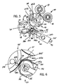
FIG. 6 is an enlarged partial side elevation view with reference to line 6-6 ofFIG. 5 , showing interaction of the nip roller overlap assembly of the present invention with one of the sheets of material and the bed roll and retard roll of the interfolding machine; -
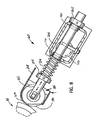
FIG. 7 is an isometric view of the nip roller overlap assembly shown inFIGS. 2-6 in combination with the retard roll of the interfolding machine; and -
FIG. 8 is an enlarged cross-sectional view taken along line 8-8 ofFig. 7 . - In describing the preferred embodiments of the invention which are illustrated in the drawings, specific terminology will be resorted to for the sake of clarity. However, it is not intended that the invention be limited to the specific terms so selected and it is to be understood that each specific term includes all technical equivalents which operate in a similar manner to accomplish a similar purpose. For example, the word "connected" or terms similar thereto are often used. Such terms are not limited to direct connection but include connection through other elements where such connection is recognized as being equivalent by those skilled in the art.
- Referring to
FIGS. 1 and2 , aninterfolding machine 25 is operable to convert a web ofmaterial 30 into a stack of interfolded sheets of material shown at 32.Interfolding machine 25 incorporates the nip roller overlap assembly of the present invention, and generally includes afirst pull roll 35 and asecond pull roll 40 that receive the web ofmaterial 30 along a path (illustrated by anarrow 42 inFIG. 2 ) from a supply roll (not shown) into theinterfolding machine 20. The first andsecond pull rolls material 30 passes, and function to unwind the web ofmaterial 30 and feed the web ofmaterial 30 in a path (illustrated by anarrow 44 inFIG. 2 ) toward a nip defined betweensecond pull roll 40 and abed roll 45. The web ofmaterial 30 is then advanced bybed roll 45 toward aknife roll 50. In a manner as is known, theknife roll 50 cuts the web of material into sheets, each of which has a predetermined length, and thebed roll 45 carries the sheets of material along a path (illustrated byarrow 52 inFIG. 2 ) toward and through a nip defined betweenbed roll 45 and aretard roll 55, which rotates at a slower speed of rotation than thebed roll 45. In a manner to be explained, theretard roll 55 cooperates with a nip roller assembly 60 (FIG. 2 ) in accordance with the present invention to form an overlap between the consecutive sheets of material. Theretard roll 55 carries the overlapped sheets of material along a path (illustrated byarrow 68 inFIG. 2 ) to alap roll 65. - The
lap roll 65 works in combination with acount roll 75 to eliminate the overlap between adjacent sheets of material at a predetermined sheet count, so as to create a separation in thestack 32 of interfolded sheets discharged from theinterfolding machine 25. Thelap roll 55 carries the overlapped sheets ofmaterial 30 along a path (illustrated byarrow 78 inFIG. 2 ) toward a nip defined between afirst assist roll 80 and an adjacentsecond assist roll 85. The first and second assist rolls 80 and 85 feed the sheets of the material to a nip defined between afirst folding roll 90 and asecond folding roll 95. - Referring to
FIG. 2 , the first andsecond folding rolls arrows 96 and 98, respectively, inFIG. 2 ) to receive the overlapped sheets of the material therebetween. The periphery of thefirst folding roll 90 generally includes a series of thegripper assemblies 100 and a series of tucker assemblies 105 uniformly and alternately spaced to interact with a series of gripper andtucker assemblies second folding roll 95. The series of alternately spaced gripper assemblies 100 andtucker assemblies 105 of the first andsecond folding rolls stack 32 of interfolded sheets. Thefolding rolls drive system 110 having a drive belt assembly 115 (FIG. 1 ). - The
stack 32 of interfolded sheets is discharged from between the first andsecond folding rolls stack 32 of interfolded sheets may be supplied to a discharge and transfer system (not shown), which guides and conveys thestack 32 from the generally vertically-aligned orientation at the discharge of theinterfolding machine 25 to a generally horizontally-aligned movement. One embodiment of a suitable discharge and transfer system is described inU.S. Patent No. 6,712,746 entitled "Discharge and Transfer System for Interfolded Sheets," filed May 5, 2000. - Referring to
FIGS. 2-5 , theoverlap assembly 20 in accordance with the present invention generally includes theretard roll 55, thebed roll 45, and thenip roll assembly 60.Retard roll 55 is mounted to ashaft 125 that rotates in a counter-clockwise direction (illustrated by arrow 68) and is positioned adjacent to thebed roll 45.Bed roll 45 is mounted on ashaft 135 that rotates in a counter-clockwise direction (illustrated by arrow 52). The speed of rotation of theshaft 125 and theretard roll 55 is approximately two-thirds of the speed of rotation of theshaft 135 and thebed roll 45, for reasons which will later be explained. Agap 140 is defined between theretard roll 55 andbed roll 45, and is dimensioned such that a consecutive series of sheets, such as shown at 145a and 145b having respective leadingedges edges 155a and 155b, can pass between theretard roll 55 and thebed roll 45. - The consecutive sheets such as 145a and 145b are initially held on the
bed roll 45 by a number ofradial suction passages 160, each of which is connected by an axial vacuum passage 165 to a vacuum source (not shown), in a manner as is known. The vacuum supplied through the axial passages 165 andradial passages 160 serves to hold the sheets such as 145a and 145b at the circumference of thebed roll 45 as thebed roll 45 rotates in thecounterclockwise direction 52. As theleading edges sheets gap 140 between thebed roll 45 and theretard roll 55, the leadingedges suction passages 160 of thebed roll 45 and are engaged by one of a series ofradial suction passages 170 formed in theretard roll 55. The retard rollsuction passages 170 are connected to a series ofaxial vacuum passages 175, which are also connected to the vacuum source described above in a manner as is known. The retard rollsuction passages 170 engage and hold the leading edges of the sheets, such as 150a and 150b downstream of the nip orgap 140, while the remainder of each sheet located upstream of the nip orgap 140 is maintained in engagement withbed roll 45 via a bedroll suction passage 160 that engages the trailing edge of each sheet. The bedroll suction passages 160 that engage the trailing edge of each sheet are supplied with vacuum to a point in the rotation ofbed roll 45 downstream of nip orgap 140, to maintain each sheet trailing edge in engagement withbed roll 45 downstream of nip orgap 140. - In order to form or create the offset or overlap of successive sheets, the leading edge such as 150b of each upstream sheet such as 145b is positioned forwardly of the trailing edge such as 155a of the next adjacent downstream sheet such as 145a. To accomplish this, the
nip roller assembly 60 includes a series of nip rolls 185 which are positioned adjacent theretard roll 55 and spaced apart from thebed roll 45. Each niproll 185 is formed of a rubber coveredidler wheel 190 affixed to one end of anidler pin 195, and is located immediately adjacent to theretard roll 55. Eachidler pin 195 is supported by ahousing 200. Eachpin 195 is held in engagement with thehousing 200 by anadjustable stop 205 and acompression spring 210. Theadjustable stop 205 is secured to the end of thepin 195 opposite thewheel 190. Thecompression spring 210 is located opposite thestop 205 and is disposed between thehousing 200 and acollar 215. Thenip roll assembly 60 also includes ashroud 218 positioned around thewheels 190 in order to ensure that the bubble created by the differential in speed between thebed roll 45 and theretard roll 55 is not prematurely sucked into the nip created by theretard rollers 185 and the retard roll55. Theshroud 218 includes a series of spacedslots 219, and each niproll 185 extends through one ofslots 219 so as to faceretard roll 55 and to form a nip orgap 220 therebetween. - In operation, the leading
edge 150a of adownstream sheet 145a is engaged withretard roll 55 via vacuum supplied to one of retard rollvacuum passages 170. When theleading edge 150a enters thenip 220 formed by theretard roll 55 and niprolls 185, the leadingedge 150a is firmly held on theretard roll 55 bysuction passages 170. Due to the difference in rotational speed between theretard roll 55 and the bed roll 45 (with theretard roll 55 rotating at a slower speed than the bed roll 45), the leadingedge 150a moves toward thenip 220 at a rate slower than the rate of advancement of the trailingedge 155a, which is retained in engagement on thebed roll 45 by one of the bedroll vacuum passages 160. This difference in the rate of advancement of the sheet 145 consequently forms a deflection orbubble 225 in the sheet 145 at a location upstream of nip rolls 185, as shown inFig. 3 . The presence of thedeflection 225 enables theleading edge 150b of thesuccessive sheet 145b to move along thebed roll 45 into engagement with theretard roll 55 via another of retard rollvacuum passages 170, so that theleading edge 150b ofsheet 145b is positioned beneath the trailingedge 155a of theprevious sheet 145a. - As shown in
FIGS. 4 and5 , the trailingedge 155a of thedownstream sheet 145a is maintained on the bed roll 130 during continued advancement by rotation ofbed roll 45, and is then released or disengaged from thebed roll 45 whenbed roll 45 reaches a predetermined point in its rotation. Such continued movement ofsheet 145a first reduces and then eliminates deflection orbubble 225 in its entirety, when the trailingedge 155a ofsheet 145a is released from engagement withbed roll 45. The trailingedge 155a then falls into contact with theshroud 218 and is directed toward and through thenip 220. Simultaneously, theleading edge 150b of theupstream sheet 145b is advanced toward nip 220 by virtue of its engagement withretard roll 55 via retardroll vacuum passage 170, which results in the formation of an overlap betweensheets leading edge 150b ofsheet 145b and the trailingedge 155a ofsheet 145a, as shown inFIG. 6 . During such advancement of theupstream sheet 145b, the trailing edge 155b of theupstream sheet 145b remains in engagement withbed roll 45, causing the formation of a deflection orbubble 225 insheet 145b, in the same manner as described previously with respect tosheet 145a. This process is continuously repeated during advancement of successive sheets, so as to produce a stream of overlappedsheets FIG. 2 ). Theshroud 218 is designed to prevent the bubble ordeflection 225 in each sheet from passing into the nip created between the retard roll nip roller185 and theretard roll 55 until thebed roll 45 has pulled the trailing end of sheet completely out of the way, and maintains the sheet bubble ordeflection 225 intact until the trailing end of the sheet is advanced to a location at which it is released from engagement withbed roll 45. - In order to enable adjustment in the force applied by the nip rolls 185 to hold the sheet leading edges such as 150a, 150 b in the
nip 220, and to accommodate any variations in the diameter ofretard roll 55 in the location of nip rolls 185, the idler pins 195 are slidably mounted within thehousing 200 for movement toward and away fromretard roll 55. As shown inFIG. 8 , the position ofstop 205 onidler pin 195 can be adjusted, to ensure that each niproll 185 provides the desired dimension of nip 220 betweenretard roll 55 and niproll 185.Idler pin 195 extends through a pair of bushings orcollars 221, which are mounted within aligned openings in opposite walls ofhousing 200 and which accommodate such axial adjustment in the position ofidler pin 185 relative tohousing 200.Compression spring 210 applies an axial biasing force onidler pin 195 that urgesidler pin 195 toward the surface ofretard roll 55. In addition,compression spring 210 can be compressed in the event an obstruction passes through nip 220, to enable niprolls 185 to temporarily move away from the surface ofretard roll 55. It can thus be appreciated thatspring 210 consistently urges thewheel 190 towards theretard roll 55 with a generally constant amount of force, with a minimum or desired distance between thewheel 190 and theretard roll 55 forming thenip 220 maintained by the location of thestop 205 on theidler pin 195. - Further, in order to vary the position of nip 220 defined by the
nip roll 185 as necessary, e.g. due to varying shapes and/or sizes of the sheet(s) 145, thehousing 200 is mounted on apivot 230 defined by a pair of stub shafts that extend outwardly from the opposite ends ofhousing 200.Pivot 230 enables the idler pins 195 to pivot, which varies the position of the idler wheels relative to the circumference ofretard roll 55, to thereby enable adjustment in the position of niproll 185 relative tobed roll 55. When the position ofidler pins 195 is adjusted in this manner, the length ofidler pin 195 outwardly ofhousing 200 is adjusted by means ofstop 205, to provide precise control of the dimension of nip 220 between nip rolls 185 and retardroll 55. - While the invention has been shown and described with respect to a specific embodiment, it is understood that a wide variety of machines or systems could be constructed in accordance with the invention defined by the claims. Hence, although the exemplary embodiment of an
overlap assembly 20 in accordance with the invention is generally described with reference to ainterfolding machine 25 for folding sheets of material into a zig-zaggedinterfolded stack 32, the application of thenip roller assembly 20 is not limited to this particular type of machine. Thenip roller assembly 20 of the invention could be employed to overlap or stagger sheets of material being fed for a wide variety of uses by various machines, and the specific embodiment and application as illustrated is not limiting on the invention.
Claims (12)
- An assembly (20) for lapping a first sheet of material with a consecutive second sheet of a material, comprising:a first roll (45) rotating at a first speed for conveying sheets of material;a second roll (55) positioned adjacent the first roll and rotating at a second speed; anda roller assembly (60) defining a nip with the second roll (55),wherein the first and second rolls (45,55) in combination with the roller assembly (60) are operable to overlap the first sheet of material (145a) and the second sheet of material (145b) by feeding the leading edge of each sheet into the nip while maintaining the sheet in engagement with the first roll (45), wherein the nip is operable to engage the leading edge of the sheet with the second roll (55) while the trailing edge of the sheet remains in engagement with the first roll (45);
characterised in that the roller assembly (60) is movable relative to the second roll (55) so as to vary the location of the nip relative to the surface of the second roll (55). - An assembly as recited in claim 1, wherein the first and second rolls (45,55) each include a plurality of radially extending passages (160,170) leading to a circumference defined by each of the first and second rolls (45,55), and wherein the successive first and second sheets of material (145a, 145b) are held at the circumference of the first and second rolls (45,55) in a timed manner by a vacuum at the radially extending passages (160,170).
- An assembly as recited in claim 1 or claim 2, wherein the roller assembly comprises:one or more wheels (190); a pin (195) that supports each of the wheels (190), each pin (195) having a first end and a second end, wherein a wheel (190) is mounted to the first end of each pin (195); anda housing (200) configured to mount the pins (195), wherein the housing (200) is pivotable about a pivot axis (230) that extends parallel to the axis of rotation of the second roll (55), wherein pivoting movement of the housing (200) about the pivot axis (230) is operable to vary the location of the nip relative to the surface of the second roll (55).
- An assembly as recited in claim 3, wherein the roller assembly (60) further includes:a collar (215) mounted to each pin (195); and a compression spring (210) mounted on the pin (195) and disposed between the collar (215) and the housing (200) for biasing the wheel (190) toward the second roll (55).
- An assembly as recited in claim 3 or claim 4, further comprising an adjustable position stop (205) interconnected with each pin (195) and engaged with the housing (200) for adjustably mounting each pin (195).
- An assembly according to any of claims 3 to 5, wherein the roller assembly (60) further includes:a shroud (218) positioned adjacent to the one or more wheels (190), the shroud (218) including one or more openings (219) to receive a portion of the circumference of each of the one or more wheels (190).
- An assembly as recited in claim 6, wherein the shroud (218) includes a generally U-shaped plate structure having a fist leg and a second leg to receive the one or more wheel (190) therebetween.
- An assembly as recited in claim 6, wherein the shroud (218) includes a generally curvilinear portion and a generally linear portion adjacent to the second roll (55), the curvilinear portion configured to receive a trailing edge (155a) of the first sheet (145a) and the overlapping portion of an adjacent second sheet (145b), the linear portion configured to disengage the trailing edge (18a) of the first sheet (145a) from the shroud (218).
- A interfolding machine to fold sheets of material, comprising:a cutting assembly (50) to cut the material into a series of sheets including a first sheet (145a) and a successive second sheet (145b);an overlap assembly (20) according to any of the preceding claims; anda first and second folding roll (96,98) configured to receive the overlapped sheets of material (145a, 145b) from the overlap assembly (20) and to fold the sheets of material (145a, 145b) into a stack of interfolded sheets.
- A method for overlapping a first sheet of material (145a) and a successive second sheet of material (145b), the method comprising the acts of:supplying the first and second sheets (145a, 145b) to a first roll (45) rotating at a first speed;transferring a leading edge (150a) of the first sheet (145a) from the first roll (45) to a second roll (55) rotating at a second speed slower than the first speed;creating a deflection in the first sheet (145a) using a roller assembly (60) located adjacent to the second roll (55);transferring a leading edge (150b) of the successive second sheet (145b) along the first roll (45) into engagement with the second roll (55); andholding a trailing edge (155a) of the first sheet (145a) with the roller assembly (60) as the second roll (55) moves the leading edge (150b) of the second sheet (145b) beneath the trailing edge (155a) of the first sheet (145a); disengaging the trailing edge (155a) of the first sheet (145a) from the roller assembly (60) into engagement with the second sheet (145b) positioned beneath; characterised by the step ofselectively moving the roller assembly (60) relative to the second roll (55) so as to vary the location of the nip relative to the surface of the second roll (55).
- A method as recited in claim 10, wherein the act of creating the deflection in the first sheet includes:holding the leading edge (150a) of the first sheet (145a) between the second roll (55) and a series of wheels (190) forming a part of the roller assembly (60); andholding the trailing edge (155a) of the first sheet (145a) with the first roll (145).
- A method as recited in claim 10, wherein the act of holding the leading edge (150a) of the first sheet (145a) between the second roll (55) and the series of wheels (190) of the roller assembly (60) includes applying an adjustable force to the series of wheels (190) that holds the leading edge of the first sheet in a nip defined by a distance between the second roll (55) and the wheels (190) of the roller assembly.
Applications Claiming Priority (4)
| Application Number | Priority Date | Filing Date | Title |
|---|---|---|---|
| US50779203P | 2003-10-01 | 2003-10-01 | |
| US507792P | 2003-10-01 | ||
| US10/953,175 US7407161B2 (en) | 2003-10-01 | 2004-09-29 | Method of and assembly for lapping consecutive sheets of web material |
| US953175 | 2004-09-29 |
Publications (3)
| Publication Number | Publication Date |
|---|---|
| EP1520822A2 EP1520822A2 (en) | 2005-04-06 |
| EP1520822A3 EP1520822A3 (en) | 2005-06-22 |
| EP1520822B1 true EP1520822B1 (en) | 2008-03-05 |
Family
ID=34316837
Family Applications (1)
| Application Number | Title | Priority Date | Filing Date |
|---|---|---|---|
| EP04256075A Expired - Lifetime EP1520822B1 (en) | 2003-10-01 | 2004-09-30 | Method of and assembly for lapping consecutive sheets of web material |
Country Status (5)
| Country | Link |
|---|---|
| US (1) | US7407161B2 (en) |
| EP (1) | EP1520822B1 (en) |
| AT (1) | ATE388113T1 (en) |
| DE (1) | DE602004012202T2 (en) |
| ES (1) | ES2301945T3 (en) |
Families Citing this family (15)
| Publication number | Priority date | Publication date | Assignee | Title |
|---|---|---|---|---|
| US7452321B2 (en) * | 2005-10-07 | 2008-11-18 | C.G. Bretting Manufacturing Company, Inc. | High speed interfolder |
| EP1826165B1 (en) | 2006-02-28 | 2009-09-16 | M T C - Macchine Trasformazione Carta S.r.l. | Modular interfolding machine allowing simple format change |
| ITBO20080002A1 (en) * | 2008-01-03 | 2009-07-04 | Gdm Spa | MACHINE AND METHOD FOR BENDING BUMPERS FOR THE CONSTRUCTION OF DIAPER PANELS. |
| ES2792374T3 (en) * | 2008-05-23 | 2020-11-11 | Mtc Macch Trasformazione Carta S R L | Multi folding machine structure |
| US9132983B2 (en) | 2010-12-17 | 2015-09-15 | Kimberly-Clark Worldwide, Inc. | Folding apparatus having rolls with variable surface speeds and a method of folding a product |
| US9132982B2 (en) | 2010-12-17 | 2015-09-15 | Kimberly-Clark Worldwide, Inc. | Folding apparatus and method of folding a product |
| US8617040B2 (en) | 2010-12-17 | 2013-12-31 | Kimberly-Clark Worldwide, Inc. | Folding apparatus and method of folding a product |
| US8602198B2 (en) | 2010-12-17 | 2013-12-10 | Kimberly-Clark Worldwide, Inc. | Vacuum roll and method of use |
| US9371209B2 (en) | 2012-05-01 | 2016-06-21 | C.G. Bretting Manufacturing Co., Inc. | Single path single web single-fold interfolder and methods |
| US8939445B2 (en) | 2013-05-30 | 2015-01-27 | Kimberly-Clark Worldwide, Inc. | Vacuum roll with internal rotary valve |
| ITUB20159653A1 (en) | 2015-12-23 | 2017-06-23 | Mtc Macch Trasformazione Carta S R L | UNIT? FOR STRETCHING OF RIBBONS, OR SHEETS OF PAPER IN PAPER TRANSFORMATION MACHINES AND BENDING AND STACKING MACHINE THAT ADOPTS SUCH UNITS? OF ADVANCEMENT |
| US10449746B2 (en) | 2016-06-27 | 2019-10-22 | C. G. Bretting Manufacturing Co., Inc. | Web processing system with multiple folding arrangements fed by a single web handling arrangement |
| IT201900001579A1 (en) | 2019-02-04 | 2020-08-04 | Mtc Macch Trasformazione Carta S R L | FOLDING UNIT, OR INTERFOLIATING, OF PAPER SHEETS FOR A PAPER TRANSFORMATION MACHINE |
| IT202100012539A1 (en) | 2021-05-14 | 2022-11-14 | Koerber Tissue Fold S R L | MACHINE FOR THE PRODUCTION OF LAMINARY PRODUCTS IN PAPER MATERIAL, IN PARTICULAR PACKS OF NAPKINS, HANDKERCHIEFS, OR SIMILAR PRODUCTS AND RELATED PRODUCTION METHOD |
| IT202300021915A1 (en) | 2023-10-20 | 2025-04-20 | Valmet Tissue Converting S R L | MACHINE FOR THE CONVERTING OF PAPER AND PRODUCT OF FOLDED OR INTERFOLDED SHEETS OBTAINABLE WITH SUCH MACHINE |
Family Cites Families (21)
| Publication number | Priority date | Publication date | Assignee | Title |
|---|---|---|---|---|
| US1624985A (en) | 1922-10-18 | 1927-04-19 | R Hoe And Co Inc | Slow-down mechanism for printed products |
| US1886312A (en) | 1929-11-30 | 1932-11-01 | Nat Paper Products Company | Paper folding machine |
| US2092952A (en) | 1934-11-26 | 1937-09-14 | Samuel J Campbell | Paper interfolding machine |
| US3096977A (en) | 1959-12-05 | 1963-07-09 | Berkley Machine Co | Apparatus for squamiform lapping of blanks |
| US3338575A (en) | 1965-03-10 | 1967-08-29 | Paper Converting Machine Co | Web lapping apparatus |
| US3490762A (en) | 1967-09-07 | 1970-01-20 | Paper Converting Machine Co | Web-lapping machine |
| US4163548A (en) | 1978-01-23 | 1979-08-07 | Paper Converting Machine Company | Method of lapping webs and product |
| US4254947A (en) | 1979-05-30 | 1981-03-10 | C. G. Bretting Mfg. Co. Inc. | Sheet overlap device |
| US4279411A (en) | 1979-06-18 | 1981-07-21 | Paper Converting Machine Company | Method of lapping webs |
| DE3524246A1 (en) | 1985-07-06 | 1987-01-08 | Will E C H Gmbh & Co | METHOD AND DEVICE FOR ZIGZAG FOLDING ENDLESS MATERIALS |
| FR2626564A1 (en) | 1988-01-29 | 1989-08-04 | Alcatel Satmam | UNIVERSAL FOLDER |
| US4991831A (en) | 1989-08-14 | 1991-02-12 | Green Ronald J | Paper sheet feeding apparatus |
| NL8902476A (en) | 1989-10-05 | 1991-05-01 | Hadewe Bv | METHOD AND DEVICE FOR FOLDING SHEETS. |
| US6090467A (en) | 1993-10-12 | 2000-07-18 | Kimberly-Clark Australia Pty Limited | Method and apparatus to manufacture a towel or tissue stack |
| US5899447A (en) | 1997-09-02 | 1999-05-04 | The Procter & Gamble Company | Apparatus for stacking pop-up towels |
| US6165116A (en) | 1999-01-12 | 2000-12-26 | Green Bay Engineering Corp. | Method and apparatus for creating a discontinuity in a stack interfolded sheets |
| DE19903120A1 (en) | 1999-01-27 | 2000-08-03 | Roland Man Druckmasch | Deceleration mechanism for products passing through a mechanical folding apparatus |
| DE10024018B4 (en) * | 2000-05-16 | 2006-05-24 | Man Roland Druckmaschinen Ag | Apparatus for forming a bow stream of scale-like partially overlapping sheets |
| US6689038B2 (en) | 2002-06-10 | 2004-02-10 | Fpna Acquisition Corporation | Method and apparatus for interrupting interfolded sheets created by a lapping interfolder |
| DE10250562A1 (en) | 2002-10-30 | 2004-05-19 | Wella Ag | Use of zein for cosmetic purposes |
| US7121994B2 (en) * | 2003-09-30 | 2006-10-17 | Fpna Acquisition Corporation | Assembly for and method of adjusting the phasing of folding rolls to create a fold in sheets of material |
-
2004
- 2004-09-29 US US10/953,175 patent/US7407161B2/en not_active Expired - Fee Related
- 2004-09-30 EP EP04256075A patent/EP1520822B1/en not_active Expired - Lifetime
- 2004-09-30 DE DE602004012202T patent/DE602004012202T2/en not_active Expired - Lifetime
- 2004-09-30 ES ES04256075T patent/ES2301945T3/en not_active Expired - Lifetime
- 2004-09-30 AT AT04256075T patent/ATE388113T1/en not_active IP Right Cessation
Also Published As
| Publication number | Publication date |
|---|---|
| US7407161B2 (en) | 2008-08-05 |
| DE602004012202D1 (en) | 2008-04-17 |
| DE602004012202T2 (en) | 2009-03-12 |
| EP1520822A2 (en) | 2005-04-06 |
| US20050073090A1 (en) | 2005-04-07 |
| ATE388113T1 (en) | 2008-03-15 |
| EP1520822A3 (en) | 2005-06-22 |
| ES2301945T3 (en) | 2008-07-01 |
Similar Documents
| Publication | Publication Date | Title |
|---|---|---|
| EP1520822B1 (en) | Method of and assembly for lapping consecutive sheets of web material | |
| US8671810B2 (en) | Folder for adjustably tensioning a web as the web is cut | |
| US4856725A (en) | Web winding machine and method | |
| EP0199286B1 (en) | Web winding machine and method | |
| US4962897A (en) | Web winding machine and method | |
| JPS605501B2 (en) | Sheet handling equipment | |
| JP4191732B2 (en) | Folding machine for rotary printing press | |
| EP1943092B1 (en) | High speed interfolder | |
| JP2002540041A (en) | Processing of sheet material | |
| EP1119453A1 (en) | High speed paper folding machine | |
| JP4968835B2 (en) | Multiple sheet production equipment | |
| EP1520818B1 (en) | Assembly for and method of adjusting the phasing of folding rolls in an interfolding machine | |
| EP2337686B1 (en) | Section for transporting printed products of variable cutoffs in a printing press folder | |
| EP2340171A1 (en) | Incremental velocity changing apparatus for transporting printed products in a printing press folder | |
| AU2012211378B2 (en) | A device and method for processing sheets of paper or of another flexible material | |
| CA2483175C (en) | Method of and assembly for lapping consecutive sheets of web material | |
| EP1520823B1 (en) | Valve System for the count roll of an interfolding machine | |
| JP2003341906A (en) | Sheet feeding device | |
| EP0296360B1 (en) | Folding apparatus | |
| JP4387582B2 (en) | Sheet discharging device | |
| JP2514826Y2 (en) | Signature distribution device for rotary printing press | |
| JP2008081229A (en) | Folding machine of rotary printing machine |
Legal Events
| Date | Code | Title | Description |
|---|---|---|---|
| PUAI | Public reference made under article 153(3) epc to a published international application that has entered the european phase |
Free format text: ORIGINAL CODE: 0009012 |
|
| AK | Designated contracting states |
Kind code of ref document: A2 Designated state(s): AT BE BG CH CY CZ DE DK EE ES FI FR GB GR HU IE IT LI LU MC NL PL PT RO SE SI SK TR |
|
| AX | Request for extension of the european patent |
Extension state: AL HR LT LV MK |
|
| PUAL | Search report despatched |
Free format text: ORIGINAL CODE: 0009013 |
|
| AK | Designated contracting states |
Kind code of ref document: A3 Designated state(s): AT BE BG CH CY CZ DE DK EE ES FI FR GB GR HU IE IT LI LU MC NL PL PT RO SE SI SK TR |
|
| AX | Request for extension of the european patent |
Extension state: AL HR LT LV MK |
|
| 17P | Request for examination filed |
Effective date: 20051003 |
|
| AKX | Designation fees paid |
Designated state(s): AT BE BG CH CY CZ DE DK EE ES FI FR GB GR HU IE IT LI LU MC NL PL PT RO SE SI SK TR |
|
| GRAP | Despatch of communication of intention to grant a patent |
Free format text: ORIGINAL CODE: EPIDOSNIGR1 |
|
| GRAS | Grant fee paid |
Free format text: ORIGINAL CODE: EPIDOSNIGR3 |
|
| GRAA | (expected) grant |
Free format text: ORIGINAL CODE: 0009210 |
|
| AK | Designated contracting states |
Kind code of ref document: B1 Designated state(s): AT BE BG CH CY CZ DE DK EE ES FI FR GB GR HU IE IT LI LU MC NL PL PT RO SE SI SK TR |
|
| REG | Reference to a national code |
Ref country code: GB Ref legal event code: FG4D |
|
| REG | Reference to a national code |
Ref country code: CH Ref legal event code: EP |
|
| REG | Reference to a national code |
Ref country code: IE Ref legal event code: FG4D |
|
| REF | Corresponds to: |
Ref document number: 602004012202 Country of ref document: DE Date of ref document: 20080417 Kind code of ref document: P |
|
| REG | Reference to a national code |
Ref country code: ES Ref legal event code: FG2A Ref document number: 2301945 Country of ref document: ES Kind code of ref document: T3 |
|
| PG25 | Lapsed in a contracting state [announced via postgrant information from national office to epo] |
Ref country code: FI Free format text: LAPSE BECAUSE OF FAILURE TO SUBMIT A TRANSLATION OF THE DESCRIPTION OR TO PAY THE FEE WITHIN THE PRESCRIBED TIME-LIMIT Effective date: 20080305 |
|
| PG25 | Lapsed in a contracting state [announced via postgrant information from national office to epo] |
Ref country code: AT Free format text: LAPSE BECAUSE OF FAILURE TO SUBMIT A TRANSLATION OF THE DESCRIPTION OR TO PAY THE FEE WITHIN THE PRESCRIBED TIME-LIMIT Effective date: 20080305 |
|
| NLV1 | Nl: lapsed or annulled due to failure to fulfill the requirements of art. 29p and 29m of the patents act | ||
| PG25 | Lapsed in a contracting state [announced via postgrant information from national office to epo] |
Ref country code: PL Free format text: LAPSE BECAUSE OF FAILURE TO SUBMIT A TRANSLATION OF THE DESCRIPTION OR TO PAY THE FEE WITHIN THE PRESCRIBED TIME-LIMIT Effective date: 20080305 Ref country code: BE Free format text: LAPSE BECAUSE OF FAILURE TO SUBMIT A TRANSLATION OF THE DESCRIPTION OR TO PAY THE FEE WITHIN THE PRESCRIBED TIME-LIMIT Effective date: 20080305 Ref country code: SI Free format text: LAPSE BECAUSE OF FAILURE TO SUBMIT A TRANSLATION OF THE DESCRIPTION OR TO PAY THE FEE WITHIN THE PRESCRIBED TIME-LIMIT Effective date: 20080305 |
|
| PG25 | Lapsed in a contracting state [announced via postgrant information from national office to epo] |
Ref country code: CZ Free format text: LAPSE BECAUSE OF FAILURE TO SUBMIT A TRANSLATION OF THE DESCRIPTION OR TO PAY THE FEE WITHIN THE PRESCRIBED TIME-LIMIT Effective date: 20080305 Ref country code: SE Free format text: LAPSE BECAUSE OF FAILURE TO SUBMIT A TRANSLATION OF THE DESCRIPTION OR TO PAY THE FEE WITHIN THE PRESCRIBED TIME-LIMIT Effective date: 20080605 Ref country code: SK Free format text: LAPSE BECAUSE OF FAILURE TO SUBMIT A TRANSLATION OF THE DESCRIPTION OR TO PAY THE FEE WITHIN THE PRESCRIBED TIME-LIMIT Effective date: 20080305 Ref country code: NL Free format text: LAPSE BECAUSE OF FAILURE TO SUBMIT A TRANSLATION OF THE DESCRIPTION OR TO PAY THE FEE WITHIN THE PRESCRIBED TIME-LIMIT Effective date: 20080305 Ref country code: PT Free format text: LAPSE BECAUSE OF FAILURE TO SUBMIT A TRANSLATION OF THE DESCRIPTION OR TO PAY THE FEE WITHIN THE PRESCRIBED TIME-LIMIT Effective date: 20080805 |
|
| ET | Fr: translation filed | ||
| PG25 | Lapsed in a contracting state [announced via postgrant information from national office to epo] |
Ref country code: RO Free format text: LAPSE BECAUSE OF FAILURE TO SUBMIT A TRANSLATION OF THE DESCRIPTION OR TO PAY THE FEE WITHIN THE PRESCRIBED TIME-LIMIT Effective date: 20080305 |
|
| REG | Reference to a national code |
Ref country code: GB Ref legal event code: 732E |
|
| PLBE | No opposition filed within time limit |
Free format text: ORIGINAL CODE: 0009261 |
|
| STAA | Information on the status of an ep patent application or granted ep patent |
Free format text: STATUS: NO OPPOSITION FILED WITHIN TIME LIMIT |
|
| PG25 | Lapsed in a contracting state [announced via postgrant information from national office to epo] |
Ref country code: DK Free format text: LAPSE BECAUSE OF FAILURE TO SUBMIT A TRANSLATION OF THE DESCRIPTION OR TO PAY THE FEE WITHIN THE PRESCRIBED TIME-LIMIT Effective date: 20080305 |
|
| 26N | No opposition filed |
Effective date: 20081208 |
|
| PG25 | Lapsed in a contracting state [announced via postgrant information from national office to epo] |
Ref country code: BG Free format text: LAPSE BECAUSE OF FAILURE TO SUBMIT A TRANSLATION OF THE DESCRIPTION OR TO PAY THE FEE WITHIN THE PRESCRIBED TIME-LIMIT Effective date: 20080605 Ref country code: EE Free format text: LAPSE BECAUSE OF FAILURE TO SUBMIT A TRANSLATION OF THE DESCRIPTION OR TO PAY THE FEE WITHIN THE PRESCRIBED TIME-LIMIT Effective date: 20080305 Ref country code: MC Free format text: LAPSE BECAUSE OF NON-PAYMENT OF DUE FEES Effective date: 20080930 |
|
| REG | Reference to a national code |
Ref country code: CH Ref legal event code: PL |
|
| PG25 | Lapsed in a contracting state [announced via postgrant information from national office to epo] |
Ref country code: IE Free format text: LAPSE BECAUSE OF NON-PAYMENT OF DUE FEES Effective date: 20080930 |
|
| REG | Reference to a national code |
Ref country code: FR Ref legal event code: TP |
|
| PG25 | Lapsed in a contracting state [announced via postgrant information from national office to epo] |
Ref country code: CY Free format text: LAPSE BECAUSE OF FAILURE TO SUBMIT A TRANSLATION OF THE DESCRIPTION OR TO PAY THE FEE WITHIN THE PRESCRIBED TIME-LIMIT Effective date: 20080305 |
|
| PG25 | Lapsed in a contracting state [announced via postgrant information from national office to epo] |
Ref country code: CH Free format text: LAPSE BECAUSE OF NON-PAYMENT OF DUE FEES Effective date: 20080930 Ref country code: LI Free format text: LAPSE BECAUSE OF NON-PAYMENT OF DUE FEES Effective date: 20080930 |
|
| PG25 | Lapsed in a contracting state [announced via postgrant information from national office to epo] |
Ref country code: HU Free format text: LAPSE BECAUSE OF FAILURE TO SUBMIT A TRANSLATION OF THE DESCRIPTION OR TO PAY THE FEE WITHIN THE PRESCRIBED TIME-LIMIT Effective date: 20080906 Ref country code: LU Free format text: LAPSE BECAUSE OF NON-PAYMENT OF DUE FEES Effective date: 20080930 |
|
| PG25 | Lapsed in a contracting state [announced via postgrant information from national office to epo] |
Ref country code: TR Free format text: LAPSE BECAUSE OF FAILURE TO SUBMIT A TRANSLATION OF THE DESCRIPTION OR TO PAY THE FEE WITHIN THE PRESCRIBED TIME-LIMIT Effective date: 20080305 |
|
| PG25 | Lapsed in a contracting state [announced via postgrant information from national office to epo] |
Ref country code: GR Free format text: LAPSE BECAUSE OF FAILURE TO SUBMIT A TRANSLATION OF THE DESCRIPTION OR TO PAY THE FEE WITHIN THE PRESCRIBED TIME-LIMIT Effective date: 20080606 |
|
| PGFP | Annual fee paid to national office [announced via postgrant information from national office to epo] |
Ref country code: IT Payment date: 20100928 Year of fee payment: 7 |
|
| PGFP | Annual fee paid to national office [announced via postgrant information from national office to epo] |
Ref country code: GB Payment date: 20110928 Year of fee payment: 8 Ref country code: FR Payment date: 20111005 Year of fee payment: 8 Ref country code: DE Payment date: 20110928 Year of fee payment: 8 Ref country code: ES Payment date: 20110720 Year of fee payment: 8 |
|
| GBPC | Gb: european patent ceased through non-payment of renewal fee |
Effective date: 20120930 |
|
| REG | Reference to a national code |
Ref country code: FR Ref legal event code: ST Effective date: 20130531 |
|
| PG25 | Lapsed in a contracting state [announced via postgrant information from national office to epo] |
Ref country code: DE Free format text: LAPSE BECAUSE OF NON-PAYMENT OF DUE FEES Effective date: 20130403 Ref country code: GB Free format text: LAPSE BECAUSE OF NON-PAYMENT OF DUE FEES Effective date: 20120930 |
|
| PG25 | Lapsed in a contracting state [announced via postgrant information from national office to epo] |
Ref country code: FR Free format text: LAPSE BECAUSE OF NON-PAYMENT OF DUE FEES Effective date: 20121001 Ref country code: IT Free format text: LAPSE BECAUSE OF NON-PAYMENT OF DUE FEES Effective date: 20120930 |
|
| REG | Reference to a national code |
Ref country code: DE Ref legal event code: R119 Ref document number: 602004012202 Country of ref document: DE Effective date: 20130403 |
|
| REG | Reference to a national code |
Ref country code: ES Ref legal event code: FD2A Effective date: 20131021 |
|
| PG25 | Lapsed in a contracting state [announced via postgrant information from national office to epo] |
Ref country code: ES Free format text: LAPSE BECAUSE OF NON-PAYMENT OF DUE FEES Effective date: 20121001 |