EP1524181A1 - Gleitboot mit Aussenbordvortrieb - Google Patents
Gleitboot mit Aussenbordvortrieb Download PDFInfo
- Publication number
- EP1524181A1 EP1524181A1 EP03023181A EP03023181A EP1524181A1 EP 1524181 A1 EP1524181 A1 EP 1524181A1 EP 03023181 A EP03023181 A EP 03023181A EP 03023181 A EP03023181 A EP 03023181A EP 1524181 A1 EP1524181 A1 EP 1524181A1
- Authority
- EP
- European Patent Office
- Prior art keywords
- boat
- engine
- water surface
- water
- flaps
- Prior art date
- Legal status (The legal status is an assumption and is not a legal conclusion. Google has not performed a legal analysis and makes no representation as to the accuracy of the status listed.)
- Withdrawn
Links
- XLYOFNOQVPJJNP-UHFFFAOYSA-N water Substances O XLYOFNOQVPJJNP-UHFFFAOYSA-N 0.000 claims abstract description 65
- 238000000034 method Methods 0.000 claims description 3
- 230000007246 mechanism Effects 0.000 claims description 2
- 238000005452 bending Methods 0.000 claims 1
- XEEYBQQBJWHFJM-UHFFFAOYSA-N Iron Chemical compound [Fe] XEEYBQQBJWHFJM-UHFFFAOYSA-N 0.000 description 28
- 229910052742 iron Inorganic materials 0.000 description 14
- 230000006870 function Effects 0.000 description 4
- 206010008479 Chest Pain Diseases 0.000 description 1
- 239000011152 fibreglass Substances 0.000 description 1
- 239000012530 fluid Substances 0.000 description 1
- 238000012986 modification Methods 0.000 description 1
- 230000004048 modification Effects 0.000 description 1
- 229920002994 synthetic fiber Polymers 0.000 description 1
- 210000001835 viscera Anatomy 0.000 description 1
Images



Classifications
-
- B—PERFORMING OPERATIONS; TRANSPORTING
- B63—SHIPS OR OTHER WATERBORNE VESSELS; RELATED EQUIPMENT
- B63B—SHIPS OR OTHER WATERBORNE VESSELS; EQUIPMENT FOR SHIPPING
- B63B1/00—Hydrodynamic or hydrostatic features of hulls or of hydrofoils
- B63B1/16—Hydrodynamic or hydrostatic features of hulls or of hydrofoils deriving additional lift from hydrodynamic forces
- B63B1/18—Hydrodynamic or hydrostatic features of hulls or of hydrofoils deriving additional lift from hydrodynamic forces of hydroplane type
- B63B1/22—Hydrodynamic or hydrostatic features of hulls or of hydrofoils deriving additional lift from hydrodynamic forces of hydroplane type with adjustable planing surfaces
-
- B—PERFORMING OPERATIONS; TRANSPORTING
- B63—SHIPS OR OTHER WATERBORNE VESSELS; RELATED EQUIPMENT
- B63B—SHIPS OR OTHER WATERBORNE VESSELS; EQUIPMENT FOR SHIPPING
- B63B1/00—Hydrodynamic or hydrostatic features of hulls or of hydrofoils
- B63B1/16—Hydrodynamic or hydrostatic features of hulls or of hydrofoils deriving additional lift from hydrodynamic forces
- B63B1/18—Hydrodynamic or hydrostatic features of hulls or of hydrofoils deriving additional lift from hydrodynamic forces of hydroplane type
- B63B1/20—Hydrodynamic or hydrostatic features of hulls or of hydrofoils deriving additional lift from hydrodynamic forces of hydroplane type having more than one planing surface
Definitions
- This invention relates to an outboard boat that can be driven at very high speed above the water surface with only its propelling device underneath the water.
- the presently available outboard boat is very practical and with high efficiency due to the successful development of outboard engine with high performance having light weight and much greater horse-power.
- the boat can be driven at very high speed and in addition, the boat body is now made of fiber glass or synthetic material which makes the boat strong and durable, with light weight and can withstand a much greater impact than in the past. Nevertheless, the position of the engine and the propeller used in the conventional outboard boat remains stationary at all time during operation. Thus, when the boat moves at a very high speed the front part of the boat is lifted up high while the rear part remains in the water, as shown in Fig. 6. When the speed is even higher and at a certain velocity, the whole boat body including its propeller is lifted above the water surface.
- the propeller blades then rotate freely in the air and give not enough force to drive the boat forward. This causes the boat to fall suddenly down and bump against the water surface. These occur alternately all the time during driving a boat at a very high speed which makes it very uncomfortable to the people sitting in the boat in addition that it can be quite harmful to their visceral organs and causes chest pain.
- the present invention describes a design of smart flying outboard boat and a method to have the whole body of a boat lifted above the water surface yet the propeller of its engine or any propelling device remains at all time under the water through a vertically movable engine which drives the boat forward at a very high speed since the friction is minimized, thus causes no bumping down of the boat body. This saves a lot of energy and makes the boat occupants feel quite comfortable all the time due to the smooth moving of the boat.
- a smart flying outboard boat which can fly above the water surface while its propeller remains rotating under the water thus minimizing the water friction to save significantly the energy required, while moving of the vehicle is quite smooth.
- the main components comprises a boat hull, an engine having a propeller mounted thereto at the lowest end of the stem of the engine where either the engine or the propelling mechanism may be movable vertically up and down automatically or manually to keep the boat driving forward at all time, and means comprises wings and controllable flaps to help uplifting and tilting of the boat body aerodynamically.
- Automatic switches, sonar detector and level gauge are installed to help driving the boat smoothly.
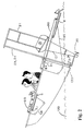
- Boat 1 is a smart flying outboard boat of the present invention. As shown in Figs. 1 and 2, the boat is driven at a velocity high enough to lift up the front part of the boat body while the rear part remains at the water surface. At this position, its engine is at the level that the blades of the propeller rotate in the water which gives a force great enough to drive the boat forward similar to that of conventional boat shown in Fig.6.
- Boat 1 is a smart flying outboard boat comprises main components as shown in Fig. 1 as follows:
- Out board Engine 2 which is an engine conventionally used in driving a boat, however, in the present invention it is installed by mounting to a movable frame 21 and iron bars 22 such that the level of the engine can be adjusted up and down vertically to a level above the water surface as desired;
- Wings 4 which projects from both sides of the hull of boat 1;
- Flaps 5 mounted underneath each wing located to the anterior part of boat 1;
- Flaps 6 mounted underneath each wing located to the posterior part of boat 1 posterior to engine 2;
- Fig. 1 As in Fig. 1, it is of light weight and with high horse power presently available. It is installed outside at the back of boat 1 with a propeller 20 at the lowest portion of a stem extending out from engine 2. The propeller rotates to drive the boat forward where during moving of the boat forward, the propeller must be underneath the water surface at all time.
- Engine 2 is mounted to frame 21 and bars 22 made of iron at the upper and the lower parts of engine 2, respectively. Frame 21 and bars 22 are welded to two vertical iron shafts 23 and 24 positioned at a predetermined distance or about 3 feet apart. As shown in Fig.
- iron shaft 23 passes through two circular spaces 25 and 28 in iron plates 27 and 30, while iron shaft 24 passes through two circular spaces 26 and 29 in iron plates 27 and 30, respectively, to have the lower end of each shaft 23 and 24 welded to an iron bar 34 at the lowest level under iron plate 30.
- Iron plates 27 and 30 are welded to the back of boat 1 at the upper and the lower level, respectively.
- Moving of engine 2 up and down vertically can be controlled by a DC motor 31 which pulls a cable 32 through a pulley 33 fixed onto iron plate 27. Cable 32 passes through circular spaces 36 and 37 in iron plates 27 and 30, respectively, to have its lowest end welded to iron bar 34.
- pulley 33 rotates counterclockwise and engine 2 is pulled vertically upward and when motor 31 releases cable 32 down, pulley 33 then rotates clockwise thus allows engine 2 move vertically downward.
- Wing 4 projects from both sides of the boat body to facilitate uplifting and good balance of the boat while moving above the water surface.
- the posterior end 40 of each wing extends further passing engine 2 with its end slightly bends down as shown in Fig. 1 to help increasing the uplift aerodynamically.
- each wing 4 At the end of each wing 4, there is an air rudder installed on top to help steering the boat through a steering wheel 100.
- Flap 5 is installed underneath each wing 4 positioned relatively to the front of the boat. Flap 5 can pivotally move about a hinge 51 fixed to wing 4.
- Pulleys 52 and 53 are installed on the boat body at a position lower and anterior to wing 4, where both pulleys have identical diameter and rotate about the same shaft 54 of motor 55 installed at the front of boat 1.
- Cable 56 drives pulleys 52 and 53 clockwise or counterclockwise through shaft 54.
- Cable 56 has its proximal end fixed to pulley 52 at the pulley groove and its distal end fixed to position 59 underneath at the posterior end of flap 5.
- Cable 56 moves in a manner that when pulley 52 rotates clockwise, cable 56 winds about the axis of pulley 52 and passes through the groove of a pulley 57 causing pulley 57 to rotate freely about shaft 58 which is fixed to the boat body lower to flap 5.
- Cable 60 has its proximal end fixed to pulley 53 at the pulley groove where it passes through circular space 61 of wing 4 and passes over a groove of pulley 62 which rotates freely about shaft 63 connected to stem 64 to hold pulley 62 up above the surface of wing 4. Cable 60 passes further over a groove of pulley 65 which rotates freely about shaft 66 connected to stem 67 to hold pulley 65 up above the surface of wing 4. The distal end of cable 60 then passes down through a rectangular space 68 to have its end fixed to position 69 at the dorsal surface of posterior end of flap 5.
- Flap 6 is installed underneath each wing 4 positioned relatively to the back of boat 1. Flap 6 can pivotally move about a hinge 80 fixed to wing 4.
- Pulleys 81 and 82 are installed at a position on the boat body lower and posterior to flap 5, where both pulleys have identical diameter and rotate about the same shaft 83 of motor 84 installed close to the back of boat 1.
- Motor 84 drives pulleys 81 and 82 clockwise or counterclockwise through shaft 83.
- Cable 85 has its proximal end fixed to pulley 81 at the pulley groove and its distal end fixed to position 88 underneath at the posterior end of flap 6. Cable 85 moves in a manner that when pulley 81 rotates clockwise, cable 85 winds about the axis of pulley 81 and passes through the groove of a pulley 86 causing pulley 86 to rotate freely about shaft 87 which is fixed to the boat body lower to flap 6.
- Cable 90 has its proximal end fixed to pulley 82 at the pulley groove where it passes through circular space 91 of wing 4 and passes over a groove of pulley 92 which rotates freely about shaft 93 connected to stem 94 to hold pulley 92 up above the surface of wing 4. Cable 90 passes further over a groove of pulley 95 which rotates freely about shaft 96 connected to stem 97 to hold pulley 95 up above the surface of wing 4. The distal end of cable 90 then passes down through a rectangular space 98 to have its end fixed to position 99 at the dorsal surface at posterior end of flap 6.
- Flap 5 and 6 help lifting the boat up above the water surface to a desired level.
- Navigation Control Systems (Fig. 5) comprises:
- pressing switch 107 causes both motors 84 on the right and the left side to work simultaneously thus pulleys 81 and 82 rotates clockwise, and cable 85 pulls flap 6 pivotally downward and at the same time cable 90 is released from pulley 82 while flap 6 moves pivotally downward.
- motor 84 starts functioning and turns pulleys 81 and 82 counterclockwise while cable 90 pulls flap 6 to move pivotally upward.
- any of the switches can be pressed to separately control moving either of the flaps on the right or the left side is to make it possible to tilt the boat right or left after the whole boat is lifted up above the water surface and the boat is in balance, yet the propeller is still under the water and rotates to drive the boat forward. This is in the same manner as that of airplane which can tilt right or left while flying in the air by controlling the ailerons. This will add much more fun to drive this newly invented boat as sport-boat.
- Switch 123 in Fig. 1, is an automatic switch installed at the lower part of stem 121 about 20 cm. above propeller 20. This switch will operate or in the 'ON' position when it is above the water surface 120 and will be in the 'OFF' position when it is dipped under the water surface 120. This switch 123 is connected to motor 31 through switch 125.
- This switch 123 is also connected directly to a buzzer 126 on the control panel 104.
- a sonar detector 130 is installed underneath boat 1 as in Fig. 1 and connected directly to a level gauge 132 on the control panel 104. This sonar detector helps indicating the distance between the boat bottom and the water surface 120 by means of reflecting sound waves. Any other devices that can detect or indicate the distance between the bottom of the boat and the water surface can also be applied.
- switch 123 Once switch 123 is above the water surface, it will be turned 'ON'. This makes the buzzer 126 start buzzing. The boat driver thus should press his left foot on switch 102 or release the accelerating pedal 101 to lower the speed of the boat. This causes switch 123 to be back under the water surface. The buzzer 126 then stops buzzing. This keeps the propeller 20 be at the level 20 centimeters under water surface at all time where it gives the best propelling force.
- uplift of the boat can be as high as desire, only that the propeller needs to be in the water at all time. But if boat 1 is lifted too high that propeller 20 is lifted over the water surface, then boat will fall down to bump against the water surface.
- Push switch 125 to 'ON' position and speed up the boat.
- propeller 20 is controlled automatically to be under the water surface 120 at all time.
- the boat will move smoothly above the water surface. This is in contrast to that controlling the engine 2 manually as in 1. where manual control is best for skillful drivers meant for fun driving or contesting.
- a level gauge 132 which is connected to the sonar detector 130 installed at the bottom of the boat.
Landscapes
- Physics & Mathematics (AREA)
- Fluid Mechanics (AREA)
- Chemical & Material Sciences (AREA)
- Engineering & Computer Science (AREA)
- Combustion & Propulsion (AREA)
- Mechanical Engineering (AREA)
- Ocean & Marine Engineering (AREA)
- Toys (AREA)
Priority Applications (1)
| Application Number | Priority Date | Filing Date | Title |
|---|---|---|---|
| EP03023181A EP1524181A1 (de) | 2003-10-13 | 2003-10-13 | Gleitboot mit Aussenbordvortrieb |
Applications Claiming Priority (1)
| Application Number | Priority Date | Filing Date | Title |
|---|---|---|---|
| EP03023181A EP1524181A1 (de) | 2003-10-13 | 2003-10-13 | Gleitboot mit Aussenbordvortrieb |
Publications (1)
| Publication Number | Publication Date |
|---|---|
| EP1524181A1 true EP1524181A1 (de) | 2005-04-20 |
Family
ID=34354442
Family Applications (1)
| Application Number | Title | Priority Date | Filing Date |
|---|---|---|---|
| EP03023181A Withdrawn EP1524181A1 (de) | 2003-10-13 | 2003-10-13 | Gleitboot mit Aussenbordvortrieb |
Country Status (1)
| Country | Link |
|---|---|
| EP (1) | EP1524181A1 (de) |
Cited By (1)
| Publication number | Priority date | Publication date | Assignee | Title |
|---|---|---|---|---|
| WO2008122834A1 (en) * | 2007-04-10 | 2008-10-16 | Mongkol Jesadanont | Boat with movable engine mount |
Citations (8)
| Publication number | Priority date | Publication date | Assignee | Title |
|---|---|---|---|---|
| US2400782A (en) * | 1944-08-03 | 1946-05-21 | A T Randall | Watercraft |
| US3016864A (en) * | 1960-06-27 | 1962-01-16 | Vinson L Woodfield | Boat construction |
| US3157146A (en) * | 1963-02-25 | 1964-11-17 | Wayne E Billig | Boat with hydrofoil and wings |
| US3230918A (en) * | 1964-10-09 | 1966-01-25 | Arthur M Compton | Ski-catamaran boat |
| US3703877A (en) * | 1969-10-17 | 1972-11-28 | Akira Ueda | Water scooter |
| US3750978A (en) * | 1971-08-25 | 1973-08-07 | B Cunningham | Skyboat |
| US3998176A (en) * | 1975-02-18 | 1976-12-21 | Lockheed Aircraft Corporation | Hydro-ski craft |
| FR2677322A1 (fr) * | 1991-12-13 | 1992-12-11 | Moulin Olivier | Suspension a double effet pour engin nautique. |
-
2003
- 2003-10-13 EP EP03023181A patent/EP1524181A1/de not_active Withdrawn
Patent Citations (8)
| Publication number | Priority date | Publication date | Assignee | Title |
|---|---|---|---|---|
| US2400782A (en) * | 1944-08-03 | 1946-05-21 | A T Randall | Watercraft |
| US3016864A (en) * | 1960-06-27 | 1962-01-16 | Vinson L Woodfield | Boat construction |
| US3157146A (en) * | 1963-02-25 | 1964-11-17 | Wayne E Billig | Boat with hydrofoil and wings |
| US3230918A (en) * | 1964-10-09 | 1966-01-25 | Arthur M Compton | Ski-catamaran boat |
| US3703877A (en) * | 1969-10-17 | 1972-11-28 | Akira Ueda | Water scooter |
| US3750978A (en) * | 1971-08-25 | 1973-08-07 | B Cunningham | Skyboat |
| US3998176A (en) * | 1975-02-18 | 1976-12-21 | Lockheed Aircraft Corporation | Hydro-ski craft |
| FR2677322A1 (fr) * | 1991-12-13 | 1992-12-11 | Moulin Olivier | Suspension a double effet pour engin nautique. |
Cited By (2)
| Publication number | Priority date | Publication date | Assignee | Title |
|---|---|---|---|---|
| WO2008122834A1 (en) * | 2007-04-10 | 2008-10-16 | Mongkol Jesadanont | Boat with movable engine mount |
| CN101610946A (zh) * | 2007-04-10 | 2009-12-23 | 蒙空·耶萨达努特 | 具有可移动发动机架的艇 |
Similar Documents
| Publication | Publication Date | Title |
|---|---|---|
| US20250229867A1 (en) | Surf wake system for a watercraft | |
| JP5599480B2 (ja) | ジェット推進舟艇のトリムおよび後進システム | |
| US9914519B2 (en) | Propulsion system for a watercraft | |
| US7854663B2 (en) | Water amusement ride | |
| US5494464A (en) | Control for jet powered watercraft | |
| CN117615964A (zh) | 可转向的水翼船舶 | |
| US6468118B1 (en) | Personal watercraft | |
| US20220363351A1 (en) | Water Sports Device | |
| CA3156767A1 (en) | Water sports device | |
| EP0411358A1 (de) | Bodeneffekt-Fluggerät | |
| US6892665B2 (en) | Smart flying outboard boat | |
| WO2016048196A1 (ru) | Система активной стабилизации малоразмерного плавательного средства | |
| HK1078837A (en) | Hydroplane boat with outboard propulsion | |
| JP4413024B2 (ja) | 水上浮上船外機付きボート | |
| JP2735110B2 (ja) | 水面滑走艇 | |
| US4862984A (en) | Amphibious air cushion vehicle | |
| CN211223775U (zh) | 用于帆船驾驶操控的可调节座椅 | |
| JP2000344186A (ja) | 翼付き艇および翼付き車および翼付きボード | |
| JP5531414B2 (ja) | 操縦支援装置 | |
| CA2023748A1 (en) | Method and apparatus for water jet trim on boats | |
| JPH04191193A (ja) | ジエツト推進式滑走艇の操縦装置 | |
| JPH05246380A (ja) | ブレーキ付きパーソナル水上機 |
Legal Events
| Date | Code | Title | Description |
|---|---|---|---|
| PUAI | Public reference made under article 153(3) epc to a published international application that has entered the european phase |
Free format text: ORIGINAL CODE: 0009012 |
|
| AK | Designated contracting states |
Kind code of ref document: A1 Designated state(s): AT BE BG CH CY CZ DE DK EE ES FI FR GB GR HU IE IT LI LU MC NL PT RO SE SI SK TR |
|
| AX | Request for extension of the european patent |
Extension state: AL LT LV MK |
|
| RTI1 | Title (correction) |
Free format text: FLYING BOAT WITH OUTBOARD PROPULSION |
|
| 17P | Request for examination filed |
Effective date: 20051017 |
|
| AKX | Designation fees paid |
Designated state(s): AT BE BG CH CY LI |
|
| RBV | Designated contracting states (corrected) |
Designated state(s): AT BE BG CH CY CZ DE DK EE ES FI FR GB GR HU IE IT LI LU MC NL PT RO SE SI SK TR |
|
| D17P | Request for examination filed (deleted) | ||
| RBV | Designated contracting states (corrected) |
Designated state(s): AT BE BG CH CY CZ DE DK EE ES FI FR GB GR HU IE IT LI LU MC NL PT RO SE SI SK TR |
|
| R17P | Request for examination filed (corrected) |
Effective date: 20051017 |
|
| D17P | Request for examination filed (deleted) | ||
| R17P | Request for examination filed (corrected) |
Effective date: 20051017 |
|
| REG | Reference to a national code |
Ref country code: HK Ref legal event code: DE Ref document number: 1078837 Country of ref document: HK |
|
| REG | Reference to a national code |
Ref country code: DE Ref legal event code: 8566 |
|
| REG | Reference to a national code |
Ref country code: HK Ref legal event code: WD Ref document number: 1078837 Country of ref document: HK |
|
| STAA | Information on the status of an ep patent application or granted ep patent |
Free format text: STATUS: THE APPLICATION IS DEEMED TO BE WITHDRAWN |
|
| 18D | Application deemed to be withdrawn |
Effective date: 20120502 |