EP1524172A1 - No backlash scissors gear and electric power steering apparatus provided therewith - Google Patents
No backlash scissors gear and electric power steering apparatus provided therewith Download PDFInfo
- Publication number
- EP1524172A1 EP1524172A1 EP04030013A EP04030013A EP1524172A1 EP 1524172 A1 EP1524172 A1 EP 1524172A1 EP 04030013 A EP04030013 A EP 04030013A EP 04030013 A EP04030013 A EP 04030013A EP 1524172 A1 EP1524172 A1 EP 1524172A1
- Authority
- EP
- European Patent Office
- Prior art keywords
- gear
- steering
- scissors
- rack
- electric motor
- Prior art date
- Legal status (The legal status is an assumption and is not a legal conclusion. Google has not performed a legal analysis and makes no representation as to the accuracy of the status listed.)
- Withdrawn
Links
- 230000006835 compression Effects 0.000 claims description 16
- 238000007906 compression Methods 0.000 claims description 16
- 238000010348 incorporation Methods 0.000 abstract description 4
- 230000007246 mechanism Effects 0.000 description 63
- 229920003002 synthetic resin Polymers 0.000 description 21
- 239000000057 synthetic resin Substances 0.000 description 21
- 229910052751 metal Inorganic materials 0.000 description 11
- 239000002184 metal Substances 0.000 description 11
- 238000005516 engineering process Methods 0.000 description 10
- 230000033001 locomotion Effects 0.000 description 10
- 229910000831 Steel Inorganic materials 0.000 description 9
- 239000010959 steel Substances 0.000 description 9
- 230000005540 biological transmission Effects 0.000 description 8
- 239000002131 composite material Substances 0.000 description 8
- 229920005989 resin Polymers 0.000 description 8
- 239000011347 resin Substances 0.000 description 8
- 239000007767 bonding agent Substances 0.000 description 5
- 230000008859 change Effects 0.000 description 4
- 230000010355 oscillation Effects 0.000 description 4
- 230000002093 peripheral effect Effects 0.000 description 4
- 230000002441 reversible effect Effects 0.000 description 4
- 238000005096 rolling process Methods 0.000 description 4
- 230000000694 effects Effects 0.000 description 3
- 238000000034 method Methods 0.000 description 3
- 230000000452 restraining effect Effects 0.000 description 2
- 239000000126 substance Substances 0.000 description 2
- 229910000838 Al alloy Inorganic materials 0.000 description 1
- 229910000881 Cu alloy Inorganic materials 0.000 description 1
- 238000010521 absorption reaction Methods 0.000 description 1
- 239000000853 adhesive Substances 0.000 description 1
- 230000001070 adhesive effect Effects 0.000 description 1
- 238000012412 chemical coupling Methods 0.000 description 1
- 238000006243 chemical reaction Methods 0.000 description 1
- 238000002485 combustion reaction Methods 0.000 description 1
- 230000003247 decreasing effect Effects 0.000 description 1
- 238000001514 detection method Methods 0.000 description 1
- 230000012447 hatching Effects 0.000 description 1
- 238000002347 injection Methods 0.000 description 1
- 239000007924 injection Substances 0.000 description 1
- 238000001746 injection moulding Methods 0.000 description 1
- 238000009434 installation Methods 0.000 description 1
- 238000000465 moulding Methods 0.000 description 1
- 238000007747 plating Methods 0.000 description 1
- 230000008569 process Effects 0.000 description 1
- 230000009467 reduction Effects 0.000 description 1
- 230000003252 repetitive effect Effects 0.000 description 1
- 238000004381 surface treatment Methods 0.000 description 1
Images


Classifications
-
- F—MECHANICAL ENGINEERING; LIGHTING; HEATING; WEAPONS; BLASTING
- F16—ENGINEERING ELEMENTS AND UNITS; GENERAL MEASURES FOR PRODUCING AND MAINTAINING EFFECTIVE FUNCTIONING OF MACHINES OR INSTALLATIONS; THERMAL INSULATION IN GENERAL
- F16H—GEARING
- F16H55/00—Elements with teeth or friction surfaces for conveying motion; Worms, pulleys or sheaves for gearing mechanisms
- F16H55/02—Toothed members; Worms
- F16H55/17—Toothed wheels
- F16H55/18—Special devices for taking up backlash
-
- B—PERFORMING OPERATIONS; TRANSPORTING
- B62—LAND VEHICLES FOR TRAVELLING OTHERWISE THAN ON RAILS
- B62D—MOTOR VEHICLES; TRAILERS
- B62D5/00—Power-assisted or power-driven steering
- B62D5/04—Power-assisted or power-driven steering electrical, e.g. using an electric servo-motor connected to, or forming part of, the steering gear
- B62D5/0421—Electric motor acting on or near steering gear
- B62D5/0424—Electric motor acting on or near steering gear the axes of motor and final driven element of steering gear, e.g. rack, being parallel
-
- B—PERFORMING OPERATIONS; TRANSPORTING
- B62—LAND VEHICLES FOR TRAVELLING OTHERWISE THAN ON RAILS
- B62D—MOTOR VEHICLES; TRAILERS
- B62D5/00—Power-assisted or power-driven steering
- B62D5/04—Power-assisted or power-driven steering electrical, e.g. using an electric servo-motor connected to, or forming part of, the steering gear
- B62D5/0442—Conversion of rotational into longitudinal movement
- B62D5/0445—Screw drives
- B62D5/0448—Ball nuts
-
- H—ELECTRICITY
- H01—ELECTRIC ELEMENTS
- H01R—ELECTRICALLY-CONDUCTIVE CONNECTIONS; STRUCTURAL ASSOCIATIONS OF A PLURALITY OF MUTUALLY-INSULATED ELECTRICAL CONNECTING ELEMENTS; COUPLING DEVICES; CURRENT COLLECTORS
- H01R24/00—Two-part coupling devices, or either of their cooperating parts, characterised by their overall structure
- H01R24/60—Contacts spaced along planar side wall transverse to longitudinal axis of engagement
- H01R24/62—Sliding engagements with one side only, e.g. modular jack coupling devices
-
- Y—GENERAL TAGGING OF NEW TECHNOLOGICAL DEVELOPMENTS; GENERAL TAGGING OF CROSS-SECTIONAL TECHNOLOGIES SPANNING OVER SEVERAL SECTIONS OF THE IPC; TECHNICAL SUBJECTS COVERED BY FORMER USPC CROSS-REFERENCE ART COLLECTIONS [XRACs] AND DIGESTS
- Y10—TECHNICAL SUBJECTS COVERED BY FORMER USPC
- Y10T—TECHNICAL SUBJECTS COVERED BY FORMER US CLASSIFICATION
- Y10T74/00—Machine element or mechanism
- Y10T74/19—Gearing
- Y10T74/19949—Teeth
- Y10T74/19963—Spur
- Y10T74/19972—Spur form
- Y10T74/19977—Antifriction
Definitions
- the present invention relates to an electric power steering apparatus for a vehicle.
- the present invention also relates to a power transmission gear suitable for use of the electric power steering apparatus.
- a steering apparatus for a vehicle has hitherto been classified into a manual type and a power assist type.
- the latter power assist type is designed to relieve the manual force by assisting the manual steering force with power taking some form.
- This power assist type steering apparatus is further classified into an electric type and a hydraulic type.
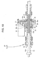
- FIG. 19 illustrates a sectional configuration of this steering apparatus.
- a first gear 21 is fixed to a rotary shaft of a motor 22.
- a second gear 32a formed integrally with a ball screw nut 32 meshes with the first gear 21.
- the ball screw nut 32 is rotatably supported by a housing 25 through bearings 28.
- a rack shaft 33 is internally fitted in the ball screw nut 32.
- the rack shaft 33 is formed with a helical groove 33b indirectly engaging through balls 26 with a helical groove 32b of the nut 32.
- a rack 33a is formed on a left sided portion, as viewed in FIG. 19, of the helical groove 33b of the rack shaft 33, and meshes with a pinion gear 36 to which a rotation of a handle 35 is transferred via a steering shaft.
- the ball screw type electric power steering apparatus in the prior art adopts the deceleration mechanism constructing by combining the gears with each other as the first gear 21, the second gear 32a and the ball screw nut 32 are combined, and therefore large operating noises emit due to sliding on a contact portion of a metal and so on.
- the deceleration mechanism using the gears composed of steels there exists a problem in which butting noises occur due to gaps between the teeth, and a driver of the vehicle might feel the noises uncomfortable.
- an electric power steering apparatus comprises a rotary shaft member connected to a steering wheel and rotating together with the steering wheel, an elongate member capable of making a rectilinear motion in either of opposite directions in order to steer dirigible wheels, a rack-and-pinion mechanism connected drivewise to the rotary shaft member and the elongate member and constructed of a pinion gear rotated by the rotary shaft member and of a rack gear provided in a first axial position of the elongate member and meshing with the pinion gear, a ball screw mechanism constructed of a screw member provided in a second axial position of the elongate member, a nut member surrounding at least a part of the screw member and a multiplicity of balls interposed between the screw member and the nut member, an electric motor unit disposed with its axis different from that of the elongate member, and a meshing type rotation decelerating mechanism including at least two pieces of meshing components in order to de
- the resin of at least the one component of the components of the rotation decelerating mechanism is joined by bonding chemically based on a metal-plastic composite making technology or by bonding of a bonding agent.
- a meshing contact surface of the synthetic resin is formed as an easy-to-slide smooth surface.
- An electric power steering apparatus comprises a rotary shaft member connected to a steering wheel and rotating together with the steering wheel, an elongate member capable of making a rectilinear motion in either of opposite directions in order to steer dirigible wheels, a rack-and-pinion mechanism connected drivewise to the rotary shaft member and the elongate member and constructed of a pinion gear rotated by the rotary shaft member and of a rack gear provided in a first axial position of the elongate member and meshing with the pinion gear, a ball screw mechanism constructed of a screw member provided in a second axial position of the elongate member, a nut member surrounding at least a part of the screw member and a multiplicity of balls interposed between the screw member and the nut member, an electric motor unit disposed with its axis different from that of the elongate member, and a meshing type rotation decelerating mechanism including three two pieces of meshing components in order to decelerate rotation of an output shaft of the electric
- the synthetic resin of the intermediate component is joined by chemical bonding based on a metal-plastic composite making technology or by bonding of a bonding agent.
- the synthetic resin absorbs oscillations when the two pieces of meshing components are brought into contact with each other, and the oscillations are restrained owing to a high slidability of the surface thereof. Therefore, the emissions of the operating noises when driving the rotation decelerating mechanism and of the butting noises due to the gaps between these components, can be prevented.
- An electric power steering apparatus comprises an electric motor, a ball screw mechanism connected to the electric motor via a gear train containing an idler gear and used for driving a rack shaft, and a steering gear case incorporating the rack shaft and the ball screw mechanism, wherein the idler gear is rotatably supported by an idler gear shaft fixed at its two side ends to the steering gear case, and a couple of bearings pre-loaded by pre-loading members is interposed between the idler gear shaft and the idler gear.
- the idler gear is supported at two points with respect to the steering gear case, thereby preventing the idler gear from falling down due to a steering reactive force.
- the bearing is preloaded by the pre-loading members, whereby a supporting rigidity of the idler gear enhances, and a backlash and noises of the idler gear become hard to occur when reversely rotated in steering.
- the idler gear is a helical gear or a double helical gear.
- the idler gear consecutively mesh with other gears, whereby the emission of the gear noises is restrained and the smooth power transmission is actualized.
- an axis C2 of an idler gear 38 deviates by a predetermined dimension 1 from a plane S' containing an axis C1 of a gear 37 on the side of an electric motor 35 and an axis C3 of a gear 39 on the side of a ball nut 41.
- the reason is that the electric motor 35 and the ball nut 41 are made closer in order to downsize the EPS apparatus with the result that an inconvenience occurs when the EPS apparatus operates.
- the idler gear 38 is, when the respective gears 37, 38, 39 are rotated in direction indicated by arrowheads in FIG. 10, biased in such a direction as to be caught in between other gears 37 and 39.
- the idler gear 38 moves corresponding to the backlash of a rolling bearing that rotationally supports the idler gear 38, and the backlash between the other hears 37 and 39 alternately changes, thereby causing uncomfortable driving noises.
- An electric power steering apparatus comprises a ball nut rotationally driven by an electric motor through a gear train containing an idler gear and having a female thread groove formed in its inner periphery, a rack shaft disposed on an axis of the ball nut and having a male thread groove so formed in its outer periphery as to face to the female thread groove, and a plurality of circulation balls interposed between the female thread groove and the male thread groove, wherein an axis of the electric motor, an axis of the idler gear and an axis of the ball nut, are disposed substantially on the same plane.
- the idler gear does not take such a form as to be caught in between the other gears also when performing the rotating operation in any direction in the EPS apparatus, and the noises due to the change in the backlash are not emitted.
- the male thread grove of the ball screw shaft that is formed in the rack shaft engages with the female thread groove formed in the ball nut through the multiplicity of circulation balls (steel balls), and the electric motor rotationally drives the ball nut, whereby the rack shaft moves in the axial direction.
- a method of transmitting the power between the electric motor and the ball nut is exemplified such as a timing belt system disclosed in Japanese Utility Model Post-Exam Publication No. 6-49489, however, what is general is a gear system disclosed in each of Japanese Patent No 3062852, Japanese Utility Model Post-Exam Publication No. 5-14939 and Japanese Utility Model Post-Exam Publication No. 2-46455.
- an idler gear is normally interposed between the gear on the side of the electric motor and the gear on the side of the ball nut in order to avoid these two gears from having large diameters.
- the helical gear and the spur gears are used as the gears of the gear train for the power transmission.
- a proper backlash is required to be provided between the gears meshing with each other for smoothly operating these gears.
- a rotating direction of the gear is changed with a reverse rotation in steering.
- the scissors gear is structured such that the spur gears are divided by half in the axial directions, the spur gears divided by half are biased in relative rotating directions by a tensile coil spring or compression coil spring, and teeth of the two pieces of spur gears seize and hold by pressure teeth of an opposite gear, thus preventing a collision occurred by a loose movement.
- This type of scissors gear requires two through four pieces of tensile coil springs or compression coil springs, and, in addition, the two spur gears need installing spaces (or storage spaces) for the tensile coils springs or compression coil springs and engaging pins as well. This leads to increases in the number of components and the number of assembling steps, and it is inevitable that the structure and the gear configuration become complicated.
- a scissors gear constituting a part of a gear train and seizing and holding by pressure teeth of a gear meshing therewith in order to restrain gear butting noises, comprises a first cylindrical gear whose tooth trace is parallel to an axis thereof;
- the first and second gears get apart from or close to each other in the axial direction, thereby seizing and holding by pressure the teeth of the gear meshing with the scissors gear. An emission of the gear butting noises due to the loose movement is prevented.
- a scissors gear constituting a part of a gear train and seizing and holding by pressure teeth of a gear meshing therewith in order to restrain gear butting noises, comprises a first cylindrical gear whose tooth trace is not parallel with an axis thereof;
- the first and second gears get apart from or close to each other in the axial direction, thereby seizing and holding by pressure the teeth of the spur gear meshing with the scissors gear. The emission of the gear butting noises due to the loose movement is prevented.
- the biasing member is a compression coil spring.
- the compression coil spring is stretched on the axis between the first gear and the second gear, whereby the two gears are made apart from each other in the axial direction by one piece of compression coil spring.
- an electric power steering apparatus for providing a steering assist by transferring a driving force of an electric motor to a steering drive component through a gear train containing a scissors gear, the scissors gear comprising a first gear, a second gear so engaging with the first gear as to be slidable in an axial direction, and a biasing member for making the first gear and the second gear apart from or close to each other in the axial direction.
- the first and second gears get apart from or close to each other in the axial direction with relative rotations, thereby seizing and holding by pressure the teeth of the gear meshing with the scissors gear. The emission of the gear butting noises due to the loose movement is prevented.
- the first and second gears may be, respectively, helical gears or spur gears.
- FIG. 1 is a perspective view illustrating car-room-sided components of an electric power steering apparatus common to all the embodiments that will hereinafter be described.
- a member indicated by a symbol 1X in FIG. 1 is a steering column, the steering column 1X supports an upper steering shaft 3X rotatably.
- a steering wheel 5X is fitted to an upper side end of the upper steering shaft 3X on one hand, and a lower steering shaft 9X is connected via a universal joint 7X to a lower side end of the shaft 3X.
- a steering gear arrangement 11X constructed of a rack-and-pinion mechanism and a power assist mechanism is connected to a lower side end of the lower steering shaft 9X.
- the symbol 13X represents a column cover for covering the steering column 1X, and the symbols 15X indicate tie rods connected to left and right side ends of the steering gear 11X.
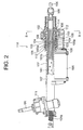
- FIG. 2 is a partial sectional view of a configuration of the electric power steering apparatus, showing a first embodiment of the first invention.
- FIG. 3 is a sectional view taken along the line B-B in FIG. 2, illustrating a gear geometry of a rotation decelerating mechanism.
- FIG. 4 is a vertical sectional view of a gear geometry of the rotation decelerating mechanism, showing a second embodiment of the first invention.
- a pinion gear 106 is fixed to a shaft 112 (see FIG. 3) separate from an output rotary shaft of a brushless electric motor 105 defined as an electric motor unit on the same axial line of this output shaft, and a deceleration gear 102 meshes with this pinion gear 106.
- the deceleration gear 102 is externally fitted on and thus fixed to a nut-shaped ball screw nut 103 or formed integrally with this screw nut 103.
- the ball screw nut 103 is so supported as to be rotatable with respect to a housing 107 through bearings 108, 108 and a nut damper 113, and is, a rack shaft 101 being internally fitted therein, i.e., so provided as to encompass this rack shaft 101.
- the rack shaft 101 is formed with a helical groove 101b engaging indirectly with a helical groove 103a of the ball screw nut 103 through balls 104.
- this ball screw nut 103 indirectly engages with the rack shaft 101 through a multiplicity of spherical balls 104 rotatably fitted in between the helical groove 103a and the helical groove 101b, and the ball screw nut 103 is fitted on a part of the helical grooves 101b in the axial direction.
- the ball screw nut 103 and the balls 104 configure a known so-called ball screw or ball thread unit.
- the pinion gear 106, the deceleration gear 102 and the ball screw nut 103 configure a rotation deceleration mechanism.
- the helical groove 101b, the ball screw nut 103 and the balls 104 configure a ball screw mechanism.
- a rack stroke damper 114 is provided at one side end of the housing 107, and works to disperse an energy caused when the housing impinges on the ball joint at the rack end.
- the electric motor 105 described above is constructed of a stator (unillustrated), a rotor (not shown) having a rotary shaft and others, and is disposed in a direction of the axis substantially parallel to the rack shaft 101 in this embodiment.
- the electric motor 105 may be disposed properly with a tilt corresponding to an installation space.
- One side end of the rack shaft 101 is connected to the tie rod 15X via the universal joint 109.
- the rack shaft 101 has a rack 101a provided at, as viewed in the drawing, a left-sided portion (a front side end) of the helical groove 101b.
- This rack 101a meshes with a pinion gear (not shown) fixedly fitted on a pinion shaft 110 connected to a lower side end of a steering shaft (unillustrated) connected to a steering wheel, and built in a pinion gear box 111.
- the steering shaft and the pinion shaft 110 configure a rotary shaft mechanism
- the rack 101a and the pinion gear configure a ran-and-pinion mechanism.
- the rack-and-pinion mechanism itself is a known mechanism that connects drivewise the rotary shaft mechanism to the rack shaft 1.
- the synthetic resin 106a has a predetermined elasticity, and a gear surface thereof is formed as a smooth surface that is easy to slide on.
- the pinion gear 106 is structured such that only the gear surface 106a is composed of the synthetic resin and the core is composed of a metal
- the synthetic resin 106a is joined to a core gear surface by a metal-plastic composite technology, for instance, as by TRI Composite Technology by Toa Denka and Tohno Seimitsu Co. Inc., wherein the gear with the whole gear surface composed of the resin 106a is formed at a stage of completing this compositing and finished by a mechanical work using a hob cutter thereafter.
- the TRI Composite Technology is a technology of joining plastic to a metal such as an aluminum alloy, a copper alloy etc within the metal mold by chemical coupling or by bonding chemically, which involves applying an electrochemical special metal surface treatment and insert injection molding. This technology provides firm joining without using any adhesive or bonding agent and is therefore capable of designing minute parts.
- a first step of joining the core metal to the resin 106a by this TRI composite making process is to execute an organic plating treatment of the tooth surface (an entire surface of outer periphery) of the core metal and to cause chemical reaction in an interior just under the tooth surface.
- this core metal is fitted into an injection metal mold, a molten resin is injected into the same metal mold, and the insert molding is then carried out, thereby bonding chemically the resin 106a to the gear surface of the core metal.
- the electric motor 105 is controlled based on information such as a torque applied to the steering wheel by the driver or a car speed etc, however, a detailed explanation of a control circuit thereof is not related directly to the present invention and is therefore omitted herein.
- the control device controls an output of the electric motor 105 to acquire a proper assisting force corresponding to the detected torque and car speed.
- the rotary shaft of the electric motor 105 is joined to the shaft of the pinion gear 106.
- the rotations of the pinion gear 106 are transferred to the ball screw nut 103 via the deceleration gear 102, thereby rotating the ball screw nut 103.
- These rotations of the ball screw nut 103 drive the rack shaft 101 in any one of directions indicated by arrowheads A, thus steering the dirigible wheels.
- a torque of the steering shaft that corresponds to a load received by the rack shaft 101 on this occasion and a car speed are detected.
- the output of the electric motor 105 is controlled corresponding to detection values thereof, whereby an electric assisting force is properly added to the manual steering force.
- the gear portion of the pinion gear 106 is composed of the synthetic resin in the first embodiment, however, the present invention is not limited to this structure, the gear portion of only the deceleration gear 102 meshing with the pinion gear 106 or the gear portions of both of these gears may also be composed of the synthetic resins. In short, a desired effect can by expected on condition that at least the gear portion, meshing with the other gear, of at least one of the gears of the rotation decelerating mechanism, be formed of the synthetic resin.
- the rotation decelerating mechanism for transferring the rotations of the output pinion gear 106 of the electric motor unit 105 to the nut-shaped ball screw nut 103 is constructed of the two components, i.e., the pinion gear 106 and the deceleration gear 102 engaging this gear 106 in the first embodiment, and, by contrast, the rotation decelerating mechanism is constructed of three components, i.e., the pinion gear 106, the deceleration gear 102 and an intermediate gear 118 interposed therebetween in the second embodiment. Accordingly, the same components as those in the first embodiment are marked with the same symbols in FIG. 4, and their repetitive explanations are omitted.
- all or any two of the three components configuring the rotation decelerating mechanism may be composed of the synthetic resins, however, preferably the whole or the gear surface of the intermediate component, i.e., the intermediate gear 118 may be composed of the synthetic resin. If only the gear surface is composed of the synthetic resin, it is preferable to adopt the TRI joining as in the first embodiment. As explained above, if only the intermediate component among the three components is composed of the synthetic resin, it is possible to reduce the gear noises such as the butting noises, the operation noises and so on at a low cost.
- the resinous gear obtained has an more improved rigidity than the resinous gear in the prior art, and therefore can decrease its own outside diameter. Hence, it is feasible to decrease an inter-axis distance between the electric motor 5 and the elongate member, i.e., the rack shaft 101.
- the contact portion, with other component, of at least one of the meshing components of the rotation decelerating mechanism is composed of the synthetic resin. Therefore, the oscillations occurred when meshing with each other are absorbed by the resin and restrained by the high slidability, and it is possible to sufficiently prevent the emission of the operation noises and the emission of the butting noises caused in the gaps between the meshing components.
- FIG. 5 is a vertical sectional view showing principal portions of the steering gear 11X of the electric power steering apparatus in an embodiment of the second invention.
- FIG. 6 is a sectional view taken along the line A-A in FIG. 5.
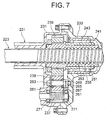
- FIG. 7 is an enlarged sectional view of a portion B in FIG. 5.
- a member indicated by the numeral 221 in FIG. 5 is a rack-and-pinion housing configuring a steering gear case.
- the rack-and-pinion housing 221 holds a rack shaft 223 and a pinion (not shown) constituting a rack-and-pinion mechanism.
- the rack shaft 223 has a rack 225 provided on the left side in FIG. 5 and meshing with the pinion, and spherical joints 227 for supporting tie rods 15X in a way that permits the tie rods 15X to oscillate, are fixed to the left and right side ends of the rack shaft 223.
- a power assist mechanism has its shell constructed of a gear housing 231 formed at a right side end, as viewed in FIG. 5, of the rack-and-pinion housing 221 and of a ball screw housing 233 fastened to the gear housing 231 by bolts and configuring the steering gear case incorporation with the rack-and-pinion housing 221.
- a front side end of an electric motor 235 is fastened by bolts to a lower portion of the gear housing 231.
- a drive gear 237 fixed to a motor shaft (unillustrated) of the electric motor 235 and a driven gear 239 meshing with the drive gear 237 through an idler gear 238, are housed between the gear housing 213 and the ball screw housing 233.
- the respective gears 237 through 239 are classified as helical gears.
- the rack shaft 223 is formed with a male thread groove 251, while the ball nut 241 is formed with a female thread groove 253.
- a multiplicity of steel balls 225 defined as circulation balls are interposed between the male thread groove 251 and the female thread groove 253. Further, the ball nut 241 is fitted with circulation pieces (unillustrated) for circulating the steel balls 255.
- the idler gear 238 is rotatably supported on an idler gear shaft 263 fixed to the gear housing 231 and the ball screw housing 233 through a couple of bearings (both of which are deep groove ball bearings in the second embodiment) 261.
- the two bearings 261 are disposed inside the idler gear 238 in the axial direction and pre-loaded by a couple of nuts (double nuts) 265, 267.
- a member designated by the numeral 269 in the drawing is a shim interposed between the nut 267 and the ball screw housing 233, and a member indicated by the numeral 271 is a bearing for supporting the drive gear 237.
- the steering gear arrangement 11X has a built-in rack-and-pinion mechanism for converting the rotational input into a rectilinear motion, and hence the rack shaft 223 moves in any one of the right and left directions, whereby the steering is performed with a change of an steering angle of the wheel through the right and left tie rods 15X.
- the electric motor 235 rotates with a predetermined rotational torque in any one of forward and reverse directions on the basis of an output of an unillustrated steering torque sensor, and the rotations of the electric motor 235 are decelerated and thus transferred to the ball but 241 via the idler gear 238 and the driven gear 239.
- a thrust acts on the male thread groove 251 of the rack shaft 223 through the steel balls 255 engaging with the female thread groove 253, thereby actualizing the steering assist.
- the idler gear shaft 263 is supported at two points by the gear housing 231 and the ball screw housing 233, and therefore the idler gear 238 does not fall down by dint of a steering reactive force etc from the rack shaft 223.
- the bearing 261 is pre-loaded, and hence almost no noise when reversely rotated in steering in combination with the gears 237 through 239 being the helical gears.
- the bearings 261 are provided in the idler gear 238, thereby decreasing an inertia of the power transmission system due to a reduction in an inertial mass of the idler gear 238, preventing an interference between the bearings 261 and 271 and downsizing the gear housing 231 and the ball screw housing 233.
- the mode of the second invention is not limited to the embodiment described above.
- the idler gear and others are formed as the helical gears in the embodiment described above but may also be formed as spur gears and double helical gears.
- the idler gear is supported on the idler gear shaft through the deep groove ball bearing in the embodiment described above, however, an angular ball bearing and a taper roller bearing may also be adopted.
- the whole configuration of the steering gear and the structure of the power assist mechanism are not limited to the exemplifications given in the embodiment explained above and may be properly modified corresponding to requests in terms of designs and specifications if within the range that does not deviate from the concept of the present invention.
- the electric power steering apparatus includes the electric motor, the ball screw mechanism connected to the electric motor via the gear train containing the idler gear and used for driving the rack shaft, and the steering gear case incorporating the rack shaft and the ball screw mechanism.
- the idler gear is rotatably supported on the idler gear shaft fixed at its two side ends to the steering gear case, the couple of bearings pre-loaded by the pre-loading members are interposed between the idler gear shaft and the idler gear, whereby the idler gear is hard to fall down by dint of the steering reactive force, and a backlash and the noises are hard to occur when reversely rotated in steering.
- FIG. 8 is a sectional plan view showing principal components of the steering gear 11X in the electric power steering (EPS) apparatus according to an embodiment of a third invention.
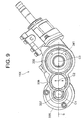
- FIG. 9 is an enlarged sectional view taken along the line A-A in FIG. 8.
- a member indicated by the numeral 321 in FIG. 8 is a rack-and-pinion housing configuring a steering gear case.
- the rack-and-pinion housing 321 holds a rack shaft 323 and a pinion (not shown) constituting a rack-and-pinion mechanism.
- the rack shaft 323 has a rack 325 provided on the left side in FIG. 8 and meshing with the pinion, and spherical joints 327 for supporting tie rods 315 in a way that permits the tie rods 15X to oscillate, are fixed to the left and right side ends of the rack shaft 323.
- a power assist mechanism has its shell constructed of a gear housing 331 defined as a second housing formed at a left side end of the rack-and-pinion housing 321 and of a ball screw housing 333 defined as a first housing fastened to the gear housing 331 by bolts and configuring the steering gear case incorporation with the rack-and-pinion housing 321.
- An electric motor 335 is fastened by bolts to a lower portion of the gear housing 331.
- the ball nut 341 is constructed of a ball nut body 343 and double-row angular ball bearings 345 fitted on the ball nut body 343.
- the rack shaft 323 is formed with a male thread groove 361, while the ball nut body 343 is formed with a female thread groove 363.
- a multiplicity of steel balls 365 defined as circulation balls are interposed between the male thread groove 361 and the female thread groove 363. Further, the ball nut body 343 is fitted with circulation pieces (unillustrated) for circulating the steel balls 365.
- an axis C1 of the drive gear 337 i.e., the electric motor 335
- an axis C2 of the idler gear 338 and an axis C3 of the driven gear 339 i.e., the ball nut 341
- the gears 337, 338, 339 are disposed on the same plane S, even if the idler gear 338 moves in upward or downward direction due to backlash of rolling bearings (unillustrated) that support rotatably the idler gear 338, the idler gear 338 is not caught into between the drive gear 337 and the driven gear 339. As a result, the backlashes between the idler gear 338, the drive gear 337 and the driven gear 339 do not change, with the result that the drive noises conceived as a problem in the prior art apparatus are not emitted.
- the electric power steering apparatus includes the ball nut rotationally driven by the electric motor through the gear train containing the idler gear and having the female thread groove formed in its inner periphery, the rack shaft disposed on the axis of this ball nut and having the male thread groove so formed in its outer periphery as to face to the female thread groove, and the plurality of circulation balls interposed between the female thread groove and the male thread groove.
- the idler gear does not take such a form as to be caught in by other gears even when operated in the rotations in any one of directions in the EPS apparatus, and the noises caused due to the changes in the backlash are not emitted.
- FIG. 11 is a sectional plan view showing principal components of the steering gear 11X in an electric power steering (EPS) apparatus in a first embodiment of a fourth invention.
- FIG. 12 is an enlarged sectional view taken along the line A-A in FIG. 11.
- a member indicated by the numeral 421 in these drawings is a rack-and-pinion housing configuring a steering gear case.
- the rack-and-pinion housing 421 holds a rack shaft 423 and a pinion (not shown) constituting a rack-and-pinion mechanism.
- the rack shaft 423 has a rack 425 provided on the left side in FIG. 11 and meshing with the pinion, and spherical joints 427 for supporting tie rods 15X in a way that permits the tie rods 15X to oscillate, are fixed to the left and right side ends of the rack shaft 423.
- a power assist mechanism has its shell constructed of a gear housing 431 defined as a second housing formed at a right side end of the rack-and-pinion housing 421 and of a ball screw housing 433 defined as a first housing fixed to the gear housing 431 by bolts and configuring the steering gear case incorporation with the rack-and-pinion housing 421.
- An electric motor 435 is fixed by bolts to a lower portion of the gear housing 431. Note that the electric motor 435 is depicted downwards for an explanatory convenience in FIG. 11.
- the respective gears 437, 438, 439 are helical gears.
- a ball nut 441 with its side end provided with the driven gear 439 is rotatably held in the ball screw housing 433.
- the ball nut 441 is constructed of a ball nut body 443 and a double-row angular ball bearing 445 fitted in the ball nut body 443.
- the rack shaft 423 is formed with a male thread groove 461, while the ball nut body 443 is formed with a female thread groove 463.
- a multiplicity of steel balls 465 defined as circulation balls are interposed between the male thread groove 461 and the female thread groove 463. Further, the ball nut body 443 is fitted with circulation pieces (unillustrated) for circulating the steel balls 465.
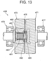
- FIG. 13 is a sectional plan view illustrating principal components of the idler gear 438 classified as the scissors gear.
- the idler gear 438 is constructed of a first helical gear 471, a second helical gear 473, and a compression coil spring 475 interposed between the two helical gears 471, 473.
- the reference numerals 477, 479 represent rolling bearings (deep groove ball bearings) that rotatably support the first and second helical gears 471, 473.
- a connecting shaft 483 having its outer peripheral surface formed with a male spline 481 is protruded from an inner side end surface of the first helical gear 471 on one hand, and a connecting hole 487 having its inner peripheral surface formed with a female spline 485 is bored in an axial core portion of the second helical gear 473 on the other hand.
- the male spline 481 engages with the female spline 485, whereby the first helical gear 471 and the second helical gear 473 are so connected to each other as to be slidable in the axial direction.
- Annular recessed portions 489, 490 are formed in the inner side end surfaces of the first and second helical gears 471, 473, and the compression coil spring 475 described above is fitted and thus accommodated in these annular recessed portions 489, 490.
- the first and second helical gears 471, 473 are formed so that tooth traces thereof become coincident just when getting close to each other with a predetermined quantity from the state shown in FIG. 13. Further, when assembling, the idler gear 438 is made to mesh with the drive gear 437 and the driven gear 439 in the state where the first and second helical gears 471, 473 get close to each other resisting a spring force of the compression coil spring 475.
- an unillustrated torque sensor detects a steering torque, whereby the electric motor 435 receives a drive current from an ECU (not shown) for the EPS apparatus and is thus actuated.
- the drive gear 437 fixed to the motor shaft of the electric motor 435 is thereby rotated, and, as indicated by the arrowheads in FIG. 12, a rotating force thereof is transferred to the driven gear 439 via the idler gear 438.
- the backlash exists between the teeth of the drive gear 437 and the teeth of the idler gear 438.
- the idler gear 438 is the scissors gear, and hence an emission of rattles (gear butting noises) attributed to this backlash is restrained.
- a backlash b exists between the drive gear 437 and the first helical gear 471, when biased by the compression coil spring 475 as shown in FIG. 14, the first and second helical gears 471, 473 become apart from each other in the axial direction, and the teeth of the two helical gears 471, 473 seizure and hold by pressure the teeth of the drive gear 437.
- FIG. 16 is a sectional plan view showing the principal components of an idler gear 438 in a second embodiment of the fourth invention.
- the idler gear 438 is constructed of a first spur gear 491, a second spur gear 493, and a compression coil spring 475 interposed between the two spur gears 491, 493.
- the reference numerals 477, 479 represent rolling bearings (deep groove ball bearings) that rotatably support the first and second spur gears 491, 493.
- a connecting shaft 497 having its outer peripheral surface formed with a male spline 495 is protruded from an inner side end surface of the first spur gear 491 on one hand; and a connecting hole 501 having its inner peripheral surface formed with a female spline 499 is bored in an axial core portion of the second spur gear 493 on the other hand.
- the male spline 495 engages with the female spline 499, whereby the first spur gears 495, 499 are so connected to each other as to be slidable in the axial direction with predetermined relative rotations.
- Annular recessed portions 489, 490 are formed in the inner side end surfaces of the first and second spur gears 491, and the compression coil spring 475 described above is fitted and thus accommodated in these annular recessed portions 487, 489.
- the first and second spur gears 491, 493 are formed so that tooth traces thereof become coincident just when getting close to each other with a predetermined quantity from the state shown in FIG. 16.
- the fourth invention is applied to the idler gear of the gear train for transmitting the driving force of the EPS apparatus and may also be applied to the scissors gear used for a power valve system of an internal combustion engine and for the power transmission system of an industrial machine.
- the embodiments described above adopt such a configuration that the couple of helical or spur gears separated away from each other by use of one piece of compression coil spring but may be made close to each other, and the biasing member may involve the use of a tensile coil spring, a belleville spring, a leaf spring and others.
- the number of these biasing members and an installing mode can be properly selected.
- the whole configuration of the steering gear and the structure of the power assist mechanism and others, may be properly modified corresponding to requests in terms of designs and specifications if within the range that does not deviate from the concept of the present invention.
- each of the scissors gear and the electric power steering apparatus of the fourth invention includes the first helical gear, the second helical gear engaging with the first helical gear so as to be slidable in the axial direction, and the biasing member that make the first and second helical gears apart from or close to each other in the axial direction.
- the first and second helical gears become apart from or close to each other in the axial direction, with the result that the teeth of the helical gears meshing with the scissors gear are seized and held by pressure. It is therefore possible, though taking the simple configuration requiring a comparatively small number of parts, to effectively prevent the emission of the gear butting noises due to the loose movement.
- the application discloses an electric power steering apparatus comprising:
- the resin of at least said one component of said components of said rotation decelerating mechanism is preferably joined by chemical bonding based on a metal-plastic composite making technology or by bonding of a bonding agent.
- a meshing contact surface of the synthetic resin is formed as an easy-to-slide smooth surface.
- the application also discloses an electric power steering apparatus comprising:
- the resin of said intermediate component is preferably joined by chemically bonding based on a metal-plastic composite making technology or by bonding of a bonding agent.
- the application also discloses electric power steering apparatus comprising:
- the idler gear is preferably a helical gear or a double helical gear.
- the application also discloses an electric power steering apparatus comprising:
- the application also discloses an electric power steering apparatus comprising: a steering shaft connectable to a steering wheel, a steering rack connected to the steering shaft by a gear mechanism; an electric motor having a motor shaft connected for power transmission to the steering rack through a gear train and a rotation decelerating mechanism; and impact absorption means to absorb impact when power is transmitted from said motor shaft to said steering rack.
Landscapes
- Engineering & Computer Science (AREA)
- Mechanical Engineering (AREA)
- Chemical & Material Sciences (AREA)
- Combustion & Propulsion (AREA)
- Transportation (AREA)
- General Engineering & Computer Science (AREA)
- Power Steering Mechanism (AREA)
- Transmission Devices (AREA)
Abstract
Description
- The present invention relates to an electric power steering apparatus for a vehicle. The present invention also relates to a power transmission gear suitable for use of the electric power steering apparatus.
- A steering apparatus for a vehicle has hitherto been classified into a manual type and a power assist type. The latter power assist type is designed to relieve the manual force by assisting the manual steering force with power taking some form. This power assist type steering apparatus is further classified into an electric type and a hydraulic type.
- The former electric type is known as an electric power steering apparatus. Within this category, an electric power steering apparatus with a deceleration mechanism using a ball screw nut is disclosed in, e.g., Japanese Patent Application Post-Exam Publication No. 6-504. FIG. 19 illustrates a sectional configuration of this steering apparatus. Referring to FIG. 19, a
first gear 21 is fixed to a rotary shaft of amotor 22. Asecond gear 32a formed integrally with aball screw nut 32 meshes with thefirst gear 21. Theball screw nut 32 is rotatably supported by ahousing 25 throughbearings 28. Arack shaft 33 is internally fitted in theball screw nut 32. Therack shaft 33 is formed with ahelical groove 33b indirectly engaging throughballs 26 with ahelical groove 32b of thenut 32. Arack 33a is formed on a left sided portion, as viewed in FIG. 19, of thehelical groove 33b of therack shaft 33, and meshes with apinion gear 36 to which a rotation of ahandle 35 is transferred via a steering shaft. - The ball screw type electric power steering apparatus in the prior art adopts the deceleration mechanism constructing by combining the gears with each other as the
first gear 21, thesecond gear 32a and theball screw nut 32 are combined, and therefore large operating noises emit due to sliding on a contact portion of a metal and so on. Especially in the case of the deceleration mechanism using the gears composed of steels, there exists a problem in which butting noises occur due to gaps between the teeth, and a driver of the vehicle might feel the noises uncomfortable. - It is an object of a first invention of the present application to provide an electric power steering apparatus capable of preventing emissions of large operating noises and butting noises by improving the inconveniences inherent in the prior arts described above.
- To accomplish the above object, according to a first aspect of the first invention of the present application, an electric power steering apparatus comprises a rotary shaft member connected to a steering wheel and rotating together with the steering wheel, an elongate member capable of making a rectilinear motion in either of opposite directions in order to steer dirigible wheels, a rack-and-pinion mechanism connected drivewise to the rotary shaft member and the elongate member and constructed of a pinion gear rotated by the rotary shaft member and of a rack gear provided in a first axial position of the elongate member and meshing with the pinion gear, a ball screw mechanism constructed of a screw member provided in a second axial position of the elongate member, a nut member surrounding at least a part of the screw member and a multiplicity of balls interposed between the screw member and the nut member, an electric motor unit disposed with its axis different from that of the elongate member, and a meshing type rotation decelerating mechanism including at least two pieces of meshing components in order to decelerate rotations of an output shaft of the electric motor unit and to transfer the decelerated rotations to the nut member of the ball screw mechanism, wherein a contact portion, with the other component, of at least the one component of the components of the rotation decelerating mechanism, is composed of a synthetic resin.
- In the electric power steering apparatus according to the first aspect of the first invention, the resin of at least the one component of the components of the rotation decelerating mechanism, is joined by bonding chemically based on a metal-plastic composite making technology or by bonding of a bonding agent.
- In the electric power steering apparatus according to the first aspect of the first invention, a meshing contact surface of the synthetic resin is formed as an easy-to-slide smooth surface.
- An electric power steering apparatus according to a second aspect of the first invention, comprises a rotary shaft member connected to a steering wheel and rotating together with the steering wheel, an elongate member capable of making a rectilinear motion in either of opposite directions in order to steer dirigible wheels, a rack-and-pinion mechanism connected drivewise to the rotary shaft member and the elongate member and constructed of a pinion gear rotated by the rotary shaft member and of a rack gear provided in a first axial position of the elongate member and meshing with the pinion gear, a ball screw mechanism constructed of a screw member provided in a second axial position of the elongate member, a nut member surrounding at least a part of the screw member and a multiplicity of balls interposed between the screw member and the nut member, an electric motor unit disposed with its axis different from that of the elongate member, and a meshing type rotation decelerating mechanism including three two pieces of meshing components in order to decelerate rotation of an output shaft of the electric motor unit and to transfer the decelerated rotation to the nut member of the ball screw mechanism, wherein a contact portion, with the other component, of the intermediate (tangent to the two other gears at the same time) of the components of the rotation decelerating mechanism, is composed of a synthetic resin.
- In the electric power steering apparatus according to the second aspect of the first invention, the synthetic resin of the intermediate component is joined by chemical bonding based on a metal-plastic composite making technology or by bonding of a bonding agent.
- With the configuration described above, the synthetic resin absorbs oscillations when the two pieces of meshing components are brought into contact with each other, and the oscillations are restrained owing to a high slidability of the surface thereof. Therefore, the emissions of the operating noises when driving the rotation decelerating mechanism and of the butting noises due to the gaps between these components, can be prevented.
- It is an object of a second invention of the present application to provide a rack assist type electric power steering apparatus constructed to ensure a rigidity and prevent noises in a power transmission system.
- An electric power steering apparatus according to the second invention comprises an electric motor, a ball screw mechanism connected to the electric motor via a gear train containing an idler gear and used for driving a rack shaft, and a steering gear case incorporating the rack shaft and the ball screw mechanism, wherein the idler gear is rotatably supported by an idler gear shaft fixed at its two side ends to the steering gear case, and a couple of bearings pre-loaded by pre-loading members is interposed between the idler gear shaft and the idler gear.
- According to the second invention, the idler gear is supported at two points with respect to the steering gear case, thereby preventing the idler gear from falling down due to a steering reactive force. Moreover, the bearing is preloaded by the pre-loading members, whereby a supporting rigidity of the idler gear enhances, and a backlash and noises of the idler gear become hard to occur when reversely rotated in steering.
- In the electric power steering apparatus according to the second invention, it is preferable that the idler gear is a helical gear or a double helical gear.
- According to the second invention, the idler gear consecutively mesh with other gears, whereby the emission of the gear noises is restrained and the smooth power transmission is actualized.
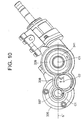
- As illustrated in FIG. 10, in the related rack assist type EPS apparatus, an axis C2 of an idler gear 38 deviates by a predetermined dimension 1 from a plane S' containing an axis C1 of a gear 37 on the side of an
electric motor 35 and an axis C3 of a gear 39 on the side of a ball nut 41. The reason is that theelectric motor 35 and the ball nut 41 are made closer in order to downsize the EPS apparatus with the result that an inconvenience occurs when the EPS apparatus operates. To be specific, the idler gear 38 is, when the respective gears 37, 38, 39 are rotated in direction indicated by arrowheads in FIG. 10, biased in such a direction as to be caught in between other gears 37 and 39. Therefore, each time there occurs a reversal rotating operation of the EPS apparatus which follows the reversal rotation in steering, the idler gear 38 moves corresponding to the backlash of a rolling bearing that rotationally supports the idler gear 38, and the backlash between the other hears 37 and 39 alternately changes, thereby causing uncomfortable driving noises. - It is an object of a third invention of the present application to provide an electric power steering apparatus constructed to restrain the operating noises due to the change in the backlash when making the reversal rotating operation.
- An electric power steering apparatus according to the third invention comprises a ball nut rotationally driven by an electric motor through a gear train containing an idler gear and having a female thread groove formed in its inner periphery, a rack shaft disposed on an axis of the ball nut and having a male thread groove so formed in its outer periphery as to face to the female thread groove, and a plurality of circulation balls interposed between the female thread groove and the male thread groove, wherein an axis of the electric motor, an axis of the idler gear and an axis of the ball nut, are disposed substantially on the same plane.
- According to the third invention, the idler gear does not take such a form as to be caught in between the other gears also when performing the rotating operation in any direction in the EPS apparatus, and the noises due to the change in the backlash are not emitted.
- Further, according to the rack assist type EPS apparatus, the male thread grove of the ball screw shaft that is formed in the rack shaft engages with the female thread groove formed in the ball nut through the multiplicity of circulation balls (steel balls), and the electric motor rotationally drives the ball nut, whereby the rack shaft moves in the axial direction. A method of transmitting the power between the electric motor and the ball nut is exemplified such as a timing belt system disclosed in Japanese Utility Model Post-Exam Publication No. 6-49489, however, what is general is a gear system disclosed in each of Japanese Patent No 3062852, Japanese Utility Model Post-Exam Publication No. 5-14939 and Japanese Utility Model Post-Exam Publication No. 2-46455. According to the rack assist type EPS apparatus taking the power transmission method based on the gear system, an idler gear is normally interposed between the gear on the side of the electric motor and the gear on the side of the ball nut in order to avoid these two gears from having large diameters.
- In the rack assist type EPS apparatus described above, the helical gear and the spur gears are used as the gears of the gear train for the power transmission. As known well, a proper backlash is required to be provided between the gears meshing with each other for smoothly operating these gears. In the case of the EPS apparatus, however, a rotating direction of the gear is changed with a reverse rotation in steering. Hence, if a driver gives a minute steering angle in forward and reverse directions as in rectilinear traveling etc, a problem that rattles (gear butting noises) are emitted. This problem is derived from the fact that the gears are rotated repeatedly in the forward and reverse directions at a comparatively short interval, and a tooth surface of the gear loosely moving by the backlash impinges on a tooth surface of the gear to be meshed with.
- There have hitherto existed the scissors gears of the types disclosed in Japanese Patent Application Laid-Open No. 2-116495 and others as a technology of restraining the butting noises of the spur gears. The scissors gear is structured such that the spur gears are divided by half in the axial directions, the spur gears divided by half are biased in relative rotating directions by a tensile coil spring or compression coil spring, and teeth of the two pieces of spur gears seize and hold by pressure teeth of an opposite gear, thus preventing a collision occurred by a loose movement. This type of scissors gear, however, requires two through four pieces of tensile coil springs or compression coil springs, and, in addition, the two spur gears need installing spaces (or storage spaces) for the tensile coils springs or compression coil springs and engaging pins as well. This leads to increases in the number of components and the number of assembling steps, and it is inevitable that the structure and the gear configuration become complicated.
- It is an object of fourth invention, which were devised under such circumstances, to provide a scissors gear capable of effectively restraining gear butting noises with a comparatively simple configuration adopted and an electric power steering apparatus using this scissors gear.
- According to an aspect of the fourth invention, a scissors gear constituting a part of a gear train and seizing and holding by pressure teeth of a gear meshing therewith in order to restrain gear butting noises, comprises a first cylindrical gear whose tooth trace is parallel to an axis thereof;
- a second cylindrical gear whose tooth trace is parallel with an axis thereof, the second gear being slidable in an axial direction with predetermined relative rotations and engageable with said first gear; and
- a biasing member for making said first gear and said second gear apart from or close to each other in the axial direction.
-
- According to the fourth invention, the first and second gears get apart from or close to each other in the axial direction, thereby seizing and holding by pressure the teeth of the gear meshing with the scissors gear. An emission of the gear butting noises due to the loose movement is prevented.
- According to a second aspect of the fourth invention, a scissors gear constituting a part of a gear train and seizing and holding by pressure teeth of a gear meshing therewith in order to restrain gear butting noises, comprises a first cylindrical gear whose tooth trace is not parallel with an axis thereof;
- a second cylindrical gear whose tooth trace is not parallel with an axis thereof, the second gear being slidable in an axial direction; and
- a biasing member for making said first gear and said second gear apart from or close to each other in the axial direction.
-
- With this configuration taken, the first and second gears get apart from or close to each other in the axial direction, thereby seizing and holding by pressure the teeth of the spur gear meshing with the scissors gear. The emission of the gear butting noises due to the loose movement is prevented.
- Further, in the scissors gear according to the fourth invention, it is preferable that the biasing member is a compression coil spring.
- According to this configuration, for instance, the compression coil spring is stretched on the axis between the first gear and the second gear, whereby the two gears are made apart from each other in the axial direction by one piece of compression coil spring.
- According to a third aspect of the fourth invention, there is provided an electric power steering apparatus for providing a steering assist by transferring a driving force of an electric motor to a steering drive component through a gear train containing a scissors gear, the scissors gear comprising a first gear, a second gear so engaging with the first gear as to be slidable in an axial direction, and a biasing member for making the first gear and the second gear apart from or close to each other in the axial direction.
- According to the third aspect of the fourth invention, the first and second gears get apart from or close to each other in the axial direction with relative rotations, thereby seizing and holding by pressure the teeth of the gear meshing with the scissors gear. The emission of the gear butting noises due to the loose movement is prevented.
- In the fifth invention, the first and second gears may be, respectively, helical gears or spur gears.
-
- FIG. 1 is a perspective view illustrating car room sided components of a steering apparatus according to the present inventions;
- FIG. 2 is a sectional view showing a configuration of an electric power steering apparatus in a first embodiment of the first invention;
- FIG. 3 is a sectional view taken along the line B-B in FIG. 1, showing a gear geometry of a rotation deceleration mechanism;
- FIG. 4 is a vertical sectional view showing a gear geometry of the rotation deceleration mechanism in a second embodiment of the first invention;
- FIG. 5 is a vertical sectional view showing principal components of a steering gear in an embodiment of a second invention;
- FIG. 6 is a sectional view taken along the line A-A in FIG. 5;
- FIG. 7 is an enlarge sectional view of a portion B in FIG. 5;
- FIG. 8 is a sectional plan view showing principal components of the steering gear in a first embodiment of a third invention;
- FIG. 9 is an enlarged sectional view taken along the line A-A in FIG. 8;
- FIG. 10 is an explanatory view showing a gear geometry in a related apparatus;
- FIG. 11 is a sectional plan view showing principal components of the steering gear in a first embodiment of a fourth invention;
- FIG. 12 is an enlarged sectional view taken along the line A-A in FIG. 11;
- FIG. 13 is a sectional plan view showing principal components of an idler gear in the first embodiment of the fourth invention;
- FIG. 14 is an explanatory view showing an operation in the first embodiment of the fourth invention;
- FIG. 15 is an explanatory view showing the operation in the first embodiment of the fourth invention;
- FIG. 16 is a sectional plan view showing principal components of the idler gear in a second embodiment of the fourth invention;
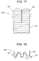
- FIG. 17 is an explanatory view showing an operation in the second embodiment of the fourth invention;
- FIG. 18 is an explanatory view showing the operation in the second embodiment of the fourth invention; and
- FIG. 19 is a sectional view showing a configuration of a conventional electric power steering apparatus.
-
- Embodiments of the present inventions will hereinafter be described with reference to the accompanying drawings.
- FIG. 1 is a perspective view illustrating car-room-sided components of an electric power steering apparatus common to all the embodiments that will hereinafter be described. A member indicated by a
symbol 1X in FIG. 1 is a steering column, thesteering column 1X supports anupper steering shaft 3X rotatably. Asteering wheel 5X is fitted to an upper side end of theupper steering shaft 3X on one hand, and alower steering shaft 9X is connected via a universal joint 7X to a lower side end of theshaft 3X. Asteering gear arrangement 11X constructed of a rack-and-pinion mechanism and a power assist mechanism is connected to a lower side end of thelower steering shaft 9X. Referring again to FIG. 1, thesymbol 13X represents a column cover for covering thesteering column 1X, and thesymbols 15X indicate tie rods connected to left and right side ends of thesteering gear 11X. - FIG. 2 is a partial sectional view of a configuration of the electric power steering apparatus, showing a first embodiment of the first invention. FIG. 3 is a sectional view taken along the line B-B in FIG. 2, illustrating a gear geometry of a rotation decelerating mechanism. FIG. 4 is a vertical sectional view of a gear geometry of the rotation decelerating mechanism, showing a second embodiment of the first invention.
- Referring to FIG. 2, a
pinion gear 106 is fixed to a shaft 112 (see FIG. 3) separate from an output rotary shaft of a brushlesselectric motor 105 defined as an electric motor unit on the same axial line of this output shaft, and adeceleration gear 102 meshes with thispinion gear 106. - The
deceleration gear 102 is externally fitted on and thus fixed to a nut-shapedball screw nut 103 or formed integrally with thisscrew nut 103. Theball screw nut 103 is so supported as to be rotatable with respect to ahousing 107 throughbearings nut damper 113, and is, arack shaft 101 being internally fitted therein, i.e., so provided as to encompass thisrack shaft 101. Therack shaft 101 is formed with ahelical groove 101b engaging indirectly with ahelical groove 103a of theball screw nut 103 throughballs 104. Namely, thisball screw nut 103 indirectly engages with therack shaft 101 through a multiplicity ofspherical balls 104 rotatably fitted in between thehelical groove 103a and thehelical groove 101b, and theball screw nut 103 is fitted on a part of thehelical grooves 101b in the axial direction. Theball screw nut 103 and theballs 104 configure a known so-called ball screw or ball thread unit. Thepinion gear 106, thedeceleration gear 102 and theball screw nut 103 configure a rotation deceleration mechanism. Thehelical groove 101b, theball screw nut 103 and theballs 104 configure a ball screw mechanism. Arack stroke damper 114 is provided at one side end of thehousing 107, and works to disperse an energy caused when the housing impinges on the ball joint at the rack end. - The
electric motor 105 described above is constructed of a stator (unillustrated), a rotor (not shown) having a rotary shaft and others, and is disposed in a direction of the axis substantially parallel to therack shaft 101 in this embodiment. Theelectric motor 105 may be disposed properly with a tilt corresponding to an installation space. One side end of therack shaft 101 is connected to thetie rod 15X via theuniversal joint 109. - The
rack shaft 101 has arack 101a provided at, as viewed in the drawing, a left-sided portion (a front side end) of thehelical groove 101b. Thisrack 101a meshes with a pinion gear (not shown) fixedly fitted on a pinion shaft 110 connected to a lower side end of a steering shaft (unillustrated) connected to a steering wheel, and built in apinion gear box 111. The steering shaft and the pinion shaft 110 configure a rotary shaft mechanism, and therack 101a and the pinion gear configure a ran-and-pinion mechanism. The rack-and-pinion mechanism itself is a known mechanism that connects drivewise the rotary shaft mechanism to the rack shaft 1. - A whole gear portion or a gear surface of the
pinion gear 106 fixed to the rotary shaft of theelectric motor 105, is composed of asynthetic resin 106a (drawn by hatching). Thesynthetic resin 106a has a predetermined elasticity, and a gear surface thereof is formed as a smooth surface that is easy to slide on. - If the
pinion gear 106 is structured such that only thegear surface 106a is composed of the synthetic resin and the core is composed of a metal, thesynthetic resin 106a is joined to a core gear surface by a metal-plastic composite technology, for instance, as by TRI Composite Technology by Toa Denka and Tohno Seimitsu Co. Inc., wherein the gear with the whole gear surface composed of theresin 106a is formed at a stage of completing this compositing and finished by a mechanical work using a hob cutter thereafter. - The TRI Composite Technology is a technology of joining plastic to a metal such as an aluminum alloy, a copper alloy etc within the metal mold by chemical coupling or by bonding chemically, which involves applying an electrochemical special metal surface treatment and insert injection molding. This technology provides firm joining without using any adhesive or bonding agent and is therefore capable of designing minute parts.
- A first step of joining the core metal to the
resin 106a by this TRI composite making process is to execute an organic plating treatment of the tooth surface (an entire surface of outer periphery) of the core metal and to cause chemical reaction in an interior just under the tooth surface. Next, this core metal is fitted into an injection metal mold, a molten resin is injected into the same metal mold, and the insert molding is then carried out, thereby bonding chemically theresin 106a to the gear surface of the core metal. - An operation in the configuration described above will briefly be explained. The
electric motor 105 is controlled based on information such as a torque applied to the steering wheel by the driver or a car speed etc, however, a detailed explanation of a control circuit thereof is not related directly to the present invention and is therefore omitted herein. The control device controls an output of theelectric motor 105 to acquire a proper assisting force corresponding to the detected torque and car speed. - Oscillations occurred when the
pinion gear 106 of theelectric motor 105 engages with thedeceleration gear 102, are absorbed by the elasticity of thesynthetic resin 106a and restrained by a high slidability of the smooth surface. Therefore, operation noises due to gear meshing are not emitted, and gear butting noises in gaps between the teeth are sufficiently prevented. - The rotary shaft of the
electric motor 105 is joined to the shaft of thepinion gear 106. In this case, the rotations of thepinion gear 106 are transferred to theball screw nut 103 via thedeceleration gear 102, thereby rotating theball screw nut 103. These rotations of theball screw nut 103 drive therack shaft 101 in any one of directions indicated by arrowheads A, thus steering the dirigible wheels. A torque of the steering shaft that corresponds to a load received by therack shaft 101 on this occasion and a car speed are detected. The output of theelectric motor 105 is controlled corresponding to detection values thereof, whereby an electric assisting force is properly added to the manual steering force. - Note that only the gear portion of the
pinion gear 106 is composed of the synthetic resin in the first embodiment, however, the present invention is not limited to this structure, the gear portion of only thedeceleration gear 102 meshing with thepinion gear 106 or the gear portions of both of these gears may also be composed of the synthetic resins. In short, a desired effect can by expected on condition that at least the gear portion, meshing with the other gear, of at least one of the gears of the rotation decelerating mechanism, be formed of the synthetic resin. - Next, a second embodiment of the first invention will be described referring to FIG. 4. A different point of the second embodiment from the first embodiment discussed above is that the rotation decelerating mechanism for transferring the rotations of the
output pinion gear 106 of theelectric motor unit 105 to the nut-shapedball screw nut 103 is constructed of the two components, i.e., thepinion gear 106 and thedeceleration gear 102 engaging thisgear 106 in the first embodiment, and, by contrast, the rotation decelerating mechanism is constructed of three components, i.e., thepinion gear 106, thedeceleration gear 102 and anintermediate gear 118 interposed therebetween in the second embodiment. Accordingly, the same components as those in the first embodiment are marked with the same symbols in FIG. 4, and their repetitive explanations are omitted. - According to the second embodiment, all or any two of the three components configuring the rotation decelerating mechanism may be composed of the synthetic resins, however, preferably the whole or the gear surface of the intermediate component, i.e., the
intermediate gear 118 may be composed of the synthetic resin. If only the gear surface is composed of the synthetic resin, it is preferable to adopt the TRI joining as in the first embodiment. As explained above, if only the intermediate component among the three components is composed of the synthetic resin, it is possible to reduce the gear noises such as the butting noises, the operation noises and so on at a low cost. Further, when adopting the TRI joining as in the first and second embodiments, the resinous gear obtained has an more improved rigidity than the resinous gear in the prior art, and therefore can decrease its own outside diameter. Hence, it is feasible to decrease an inter-axis distance between the electric motor 5 and the elongate member, i.e., therack shaft 101. - According to the first invention, the contact portion, with other component, of at least one of the meshing components of the rotation decelerating mechanism is composed of the synthetic resin. Therefore, the oscillations occurred when meshing with each other are absorbed by the resin and restrained by the high slidability, and it is possible to sufficiently prevent the emission of the operation noises and the emission of the butting noises caused in the gaps between the meshing components.
- An embodiment of a second invention will hereinafter be discussed with reference to the accompanying drawings.
- FIG. 5 is a vertical sectional view showing principal portions of the
steering gear 11X of the electric power steering apparatus in an embodiment of the second invention. FIG. 6 is a sectional view taken along the line A-A in FIG. 5. FIG. 7 is an enlarged sectional view of a portion B in FIG. 5. A member indicated by the numeral 221 in FIG. 5 is a rack-and-pinion housing configuring a steering gear case. The rack-and-pinion housing 221 holds arack shaft 223 and a pinion (not shown) constituting a rack-and-pinion mechanism. Therack shaft 223 has arack 225 provided on the left side in FIG. 5 and meshing with the pinion, andspherical joints 227 for supportingtie rods 15X in a way that permits thetie rods 15X to oscillate, are fixed to the left and right side ends of therack shaft 223. - A power assist mechanism has its shell constructed of a
gear housing 231 formed at a right side end, as viewed in FIG. 5, of the rack-and-pinion housing 221 and of aball screw housing 233 fastened to thegear housing 231 by bolts and configuring the steering gear case incorporation with the rack-and-pinion housing 221. A front side end of anelectric motor 235 is fastened by bolts to a lower portion of thegear housing 231. Further, adrive gear 237 fixed to a motor shaft (unillustrated) of theelectric motor 235 and a drivengear 239 meshing with thedrive gear 237 through anidler gear 238, are housed between the gear housing 213 and the ball screwhousing 233. Then, aball nut 241 with its outer periphery to which the drivengear 239 is spline-fitted, is rotatably held through double-rowangular ball bearings 243 in the ball screwhousing 233. According to the second embodiment, therespective gears 237 through 239 are classified as helical gears. - The
rack shaft 223 is formed with amale thread groove 251, while theball nut 241 is formed with afemale thread groove 253. A multiplicity ofsteel balls 225 defined as circulation balls are interposed between themale thread groove 251 and thefemale thread groove 253. Further, theball nut 241 is fitted with circulation pieces (unillustrated) for circulating thesteel balls 255. - As shown in FIG. 7, the
idler gear 238 is rotatably supported on anidler gear shaft 263 fixed to thegear housing 231 and the ball screwhousing 233 through a couple of bearings (both of which are deep groove ball bearings in the second embodiment) 261. The twobearings 261 are disposed inside theidler gear 238 in the axial direction and pre-loaded by a couple of nuts (double nuts) 265, 267. A member designated by the numeral 269 in the drawing is a shim interposed between thenut 267 and the ball screwhousing 233, and a member indicated by the numeral 271 is a bearing for supporting thedrive gear 237. - An operation in the second embodiment will hereinafter be described.
- When the driver rotates the
steering wheel 5X (see FIG. 1), a rotating force thereof is transferred to thesteering gear 11X via theupper steering shaft 3X and thelower steering shaft 9X. Thesteering gear arrangement 11X has a built-in rack-and-pinion mechanism for converting the rotational input into a rectilinear motion, and hence therack shaft 223 moves in any one of the right and left directions, whereby the steering is performed with a change of an steering angle of the wheel through the right and lefttie rods 15X. On this occasion, within the power assist mechanism, theelectric motor 235 rotates with a predetermined rotational torque in any one of forward and reverse directions on the basis of an output of an unillustrated steering torque sensor, and the rotations of theelectric motor 235 are decelerated and thus transferred to the ball but 241 via theidler gear 238 and the drivengear 239. When theball nut 241 rotates, a thrust acts on themale thread groove 251 of therack shaft 223 through thesteel balls 255 engaging with thefemale thread groove 253, thereby actualizing the steering assist. - According to the second embodiment, the
idler gear shaft 263 is supported at two points by thegear housing 231 and the ball screwhousing 233, and therefore theidler gear 238 does not fall down by dint of a steering reactive force etc from therack shaft 223. Further, thebearing 261 is pre-loaded, and hence almost no noise when reversely rotated in steering in combination with thegears 237 through 239 being the helical gears. Further, thebearings 261 are provided in theidler gear 238, thereby decreasing an inertia of the power transmission system due to a reduction in an inertial mass of theidler gear 238, preventing an interference between thebearings gear housing 231 and the ball screwhousing 233. - The discussion on the embodiment of the second invention comes to an end so far, however, the mode of the second invention is not limited to the embodiment described above. For instance, the idler gear and others are formed as the helical gears in the embodiment described above but may also be formed as spur gears and double helical gears. Moreover, the idler gear is supported on the idler gear shaft through the deep groove ball bearing in the embodiment described above, however, an angular ball bearing and a taper roller bearing may also be adopted. Furthermore, the whole configuration of the steering gear and the structure of the power assist mechanism, are not limited to the exemplifications given in the embodiment explained above and may be properly modified corresponding to requests in terms of designs and specifications if within the range that does not deviate from the concept of the present invention.
- As discussed above, the electric power steering apparatus according to the second invention includes the electric motor, the ball screw mechanism connected to the electric motor via the gear train containing the idler gear and used for driving the rack shaft, and the steering gear case incorporating the rack shaft and the ball screw mechanism. In the thus constructed electric power steering apparatus, the idler gear is rotatably supported on the idler gear shaft fixed at its two side ends to the steering gear case, the couple of bearings pre-loaded by the pre-loading members are interposed between the idler gear shaft and the idler gear, whereby the idler gear is hard to fall down by dint of the steering reactive force, and a backlash and the noises are hard to occur when reversely rotated in steering.
- FIG. 8 is a sectional plan view showing principal components of the
steering gear 11X in the electric power steering (EPS) apparatus according to an embodiment of a third invention. FIG. 9 is an enlarged sectional view taken along the line A-A in FIG. 8. A member indicated by the numeral 321 in FIG. 8 is a rack-and-pinion housing configuring a steering gear case. The rack-and-pinion housing 321 holds arack shaft 323 and a pinion (not shown) constituting a rack-and-pinion mechanism. Therack shaft 323 has arack 325 provided on the left side in FIG. 8 and meshing with the pinion, andspherical joints 327 for supporting tie rods 315 in a way that permits thetie rods 15X to oscillate, are fixed to the left and right side ends of therack shaft 323. - A power assist mechanism has its shell constructed of a
gear housing 331 defined as a second housing formed at a left side end of the rack-and-pinion housing 321 and of aball screw housing 333 defined as a first housing fastened to thegear housing 331 by bolts and configuring the steering gear case incorporation with the rack-and-pinion housing 321. Anelectric motor 335 is fastened by bolts to a lower portion of thegear housing 331. - A
drive gear 337 fixed to a motor shaft (unillustrated) of theelectric motor 335 and a drivengear 339 meshing with thedrive gear 337 through anidler gear 338, are housed between the gear housing 313 and the ball screwhousing 333. Further, aball nut 341 with its side end provided with the drivengear 339 is rotatably held in the ball screwhousing 333. Theball nut 341 is constructed of aball nut body 343 and double-rowangular ball bearings 345 fitted on theball nut body 343. - The
rack shaft 323 is formed with amale thread groove 361, while theball nut body 343 is formed with afemale thread groove 363. A multiplicity ofsteel balls 365 defined as circulation balls are interposed between themale thread groove 361 and thefemale thread groove 363. Further, theball nut body 343 is fitted with circulation pieces (unillustrated) for circulating thesteel balls 365. - As shown in FIG. 9, in the EPS apparatus in this embodiment, an axis C1 of the drive gear 337 (i.e., the electric motor 335), an axis C2 of the
idler gear 338 and an axis C3 of the driven gear 339 (i.e., the ball nut 341), are disposed on the same plane S. - An operation of this embodiment will hereinafter be explained.
- When the driver steers the
steering wheel 5X in any one of the right and left directions, therespective gears idler gear 338 is biased upwards in FIG. 9. Further, when the driver steers thesteering wheel 5X in the reversed direction, therespective gears idler gear 338 is biased downwards in FIG. 9. - According to this embodiment, however, since the
gears idler gear 338 moves in upward or downward direction due to backlash of rolling bearings (unillustrated) that support rotatably theidler gear 338, theidler gear 338 is not caught into between thedrive gear 337 and the drivengear 339. As a result, the backlashes between theidler gear 338, thedrive gear 337 and the drivengear 339 do not change, with the result that the drive noises conceived as a problem in the prior art apparatus are not emitted. - The discussion on the embodiment of the third invention comes to an end so far, however; the mode of the third invention is not limited to the embodiment described above. The whole configuration of the steering gear arrangement and the structure of the power assist mechanism, may be properly modified corresponding to requests in terms of designs and specifications if within the range that does not deviate from the concept of the present invention.
- As discussed above, the electric power steering apparatus according to the third invention includes the ball nut rotationally driven by the electric motor through the gear train containing the idler gear and having the female thread groove formed in its inner periphery, the rack shaft disposed on the axis of this ball nut and having the male thread groove so formed in its outer periphery as to face to the female thread groove, and the plurality of circulation balls interposed between the female thread groove and the male thread groove. In the thus constructed electric power steering apparatus; since the axis of the electric motor, the axis of the idler gear and the axis of the ball nut are disposed substantially on the same plane, the idler gear does not take such a form as to be caught in by other gears even when operated in the rotations in any one of directions in the EPS apparatus, and the noises caused due to the changes in the backlash are not emitted.
- FIG. 11 is a sectional plan view showing principal components of the
steering gear 11X in an electric power steering (EPS) apparatus in a first embodiment of a fourth invention. FIG. 12 is an enlarged sectional view taken along the line A-A in FIG. 11. A member indicated by the numeral 421 in these drawings is a rack-and-pinion housing configuring a steering gear case. The rack-and-pinion housing 421 holds arack shaft 423 and a pinion (not shown) constituting a rack-and-pinion mechanism. Therack shaft 423 has arack 425 provided on the left side in FIG. 11 and meshing with the pinion, andspherical joints 427 for supportingtie rods 15X in a way that permits thetie rods 15X to oscillate, are fixed to the left and right side ends of therack shaft 423. - A power assist mechanism has its shell constructed of a
gear housing 431 defined as a second housing formed at a right side end of the rack-and-pinion housing 421 and of aball screw housing 433 defined as a first housing fixed to thegear housing 431 by bolts and configuring the steering gear case incorporation with the rack-and-pinion housing 421. Anelectric motor 435 is fixed by bolts to a lower portion of thegear housing 431. Note that theelectric motor 435 is depicted downwards for an explanatory convenience in FIG. 11. - A
drive gear 437 fixed to a motor shaft (unillustrated) of theelectric motor 435 and a drivengear 439 meshing with thedrive gear 437 through anidler gear 438 classified as a scissors gear, are housed between the gear housing 413 and the ball screwhousing 433. In the case of this embodiment, therespective gears - A
ball nut 441 with its side end provided with the drivengear 439 is rotatably held in the ball screwhousing 433. Theball nut 441 is constructed of aball nut body 443 and a double-rowangular ball bearing 445 fitted in theball nut body 443. - The
rack shaft 423 is formed with amale thread groove 461, while theball nut body 443 is formed with afemale thread groove 463. A multiplicity ofsteel balls 465 defined as circulation balls are interposed between themale thread groove 461 and thefemale thread groove 463. Further, theball nut body 443 is fitted with circulation pieces (unillustrated) for circulating thesteel balls 465. - FIG. 13 is a sectional plan view illustrating principal components of the
idler gear 438 classified as the scissors gear. As shown in FIG. 13, theidler gear 438 is constructed of a firsthelical gear 471, a secondhelical gear 473, and acompression coil spring 475 interposed between the twohelical gears reference numerals helical gears - A connecting
shaft 483 having its outer peripheral surface formed with amale spline 481 is protruded from an inner side end surface of the firsthelical gear 471 on one hand, and a connectinghole 487 having its inner peripheral surface formed with afemale spline 485 is bored in an axial core portion of the secondhelical gear 473 on the other hand. Themale spline 481 engages with thefemale spline 485, whereby the firsthelical gear 471 and the secondhelical gear 473 are so connected to each other as to be slidable in the axial direction. - Annular recessed
portions helical gears compression coil spring 475 described above is fitted and thus accommodated in these annular recessedportions helical gears idler gear 438 is made to mesh with thedrive gear 437 and the drivengear 439 in the state where the first and secondhelical gears compression coil spring 475. - An operation of this embodiment will hereinafter be explained.
- When the driver steers the
steering wheel 5X in any one of the right and left directions, an unillustrated torque sensor detects a steering torque, whereby theelectric motor 435 receives a drive current from an ECU (not shown) for the EPS apparatus and is thus actuated. Thedrive gear 437 fixed to the motor shaft of theelectric motor 435 is thereby rotated, and, as indicated by the arrowheads in FIG. 12, a rotating force thereof is transferred to the drivengear 439 via theidler gear 438. - Normally, the backlash exists between the teeth of the
drive gear 437 and the teeth of theidler gear 438. According to this embodiment, however, theidler gear 438 is the scissors gear, and hence an emission of rattles (gear butting noises) attributed to this backlash is restrained. Namely, if a backlash b exists between thedrive gear 437 and the firsthelical gear 471, when biased by thecompression coil spring 475 as shown in FIG. 14, the first and secondhelical gears helical gears drive gear 437. - With this configuration, it does not happen in this embodiment that the
drive gear 437 loosely moves with respect to theidler gear 438 when reversely rotated in steering, and a silence when the EPS apparatus operates is remarkably improved. Note that the discussion made so far is related to thedrive gear 437 and theidler gear 438, however, the same effect can be obtained with respect to theidler gear 438 and the drivengear 439 if the quantity of the backlash remains unchanged. - FIG. 16 is a sectional plan view showing the principal components of an
idler gear 438 in a second embodiment of the fourth invention. As shown in FIG. 16, theidler gear 438 is constructed of afirst spur gear 491, asecond spur gear 493, and acompression coil spring 475 interposed between the twospur gears reference numerals - A connecting
shaft 497 having its outer peripheral surface formed with amale spline 495 is protruded from an inner side end surface of thefirst spur gear 491 on one hand; and a connecting hole 501 having its inner peripheral surface formed with afemale spline 499 is bored in an axial core portion of thesecond spur gear 493 on the other hand. Themale spline 495 engages with thefemale spline 499, whereby the first spur gears 495, 499 are so connected to each other as to be slidable in the axial direction with predetermined relative rotations. - Annular recessed
portions compression coil spring 475 described above is fitted and thus accommodated in these annular recessedportions - An operation of the second embodiment of the fourth invention will hereinafter be explained.
- If a backlash b' exists between the
drive gear 437 and thefirst spur gear 491, when biased by thecompression coil spring 475 as shown in FIG. 17, the first and second spur gears 491, 493 rotate while becoming apart from each other in the axial direction, and, as illustrated in FIG. 18, the teeth of the twospur gears drive gear 437. - With this configuration, it does not happen in this second embodiment that the
drive gear 437 loosely moves with respect to theidler gear 438 when reversely rotated in steering, and the silence when the EPS apparatus operates is remarkably improved. Note that the discussion made so far is related to thedrive gear 437 and theidler gear 438, however, the same effect can be obtained with respect to theidler gear 438 and the drivengear 439 if the quantity of the backlash remains unchanged. - The discussions on the specific embodiments of the fourth invention come to an end so far, however, the mode of the fourth invention is not restricted to the embodiments described above. For example, in the embodiments given above, the fourth invention is applied to the idler gear of the gear train for transmitting the driving force of the EPS apparatus and may also be applied to the scissors gear used for a power valve system of an internal combustion engine and for the power transmission system of an industrial machine. Further, the embodiments described above adopt such a configuration that the couple of helical or spur gears separated away from each other by use of one piece of compression coil spring but may be made close to each other, and the biasing member may involve the use of a tensile coil spring, a belleville spring, a leaf spring and others. The number of these biasing members and an installing mode can be properly selected. The whole configuration of the steering gear and the structure of the power assist mechanism and others, may be properly modified corresponding to requests in terms of designs and specifications if within the range that does not deviate from the concept of the present invention.
- As discussed above, each of the scissors gear and the electric power steering apparatus of the fourth invention, includes the first helical gear, the second helical gear engaging with the first helical gear so as to be slidable in the axial direction, and the biasing member that make the first and second helical gears apart from or close to each other in the axial direction. With this configuration, the first and second helical gears become apart from or close to each other in the axial direction, with the result that the teeth of the helical gears meshing with the scissors gear are seized and held by pressure. It is therefore possible, though taking the simple configuration requiring a comparatively small number of parts, to effectively prevent the emission of the gear butting noises due to the loose movement.
- The application discloses an electric power steering apparatus comprising:
- a rotary shaft member connected to a steering wheel and rotating together with the steering wheel;
- an elongate member capable of making a rectilinear motion in either of opposite directions in order to steer dirigible wheels;
- a rack-and-pinion mechanism connected drivewise to said rotary shaft member and said elongate member and constructed of a pinion gear rotated by said rotary shaft member and of a rack gear provided in a first axial position of said elongate member and meshing with said pinion gear;
- a ball screw mechanism constructed of a screw member provided in a second axial position of said elongate member, a nut member surrounding at least a part of said screw member and a multiplicity of balls interposed between said screw member and said nut member;
- an electric motor unit disposed with its axis different from that of said elongate member; and
- a meshing type rotation decelerating mechanism including at least two pieces of meshing components in order to decelerate rotations of an output shaft of said electric motor unit and to transfer the decelerated rotation to said nut member of said ball screw mechanism, wherein a contact portion, with said other component, of at least said one component of said components of said rotation decelerating mechanism, is composed of a synthetic resin.
-
- In this electric power steering apparatus, the resin of at least said one component of said components of said rotation decelerating mechanism, is preferably joined by chemical bonding based on a metal-plastic composite making technology or by bonding of a bonding agent. A meshing contact surface of the synthetic resin is formed as an easy-to-slide smooth surface.
- The application also discloses an electric power steering apparatus comprising:
- a rotary shaft member connected to a steering wheel and rotating together with the steering wheel;
- an elongate member capable of making a rectilinear motion in either of opposite directions in order to steer dirigible wheels;
- a rack-and-pinion mechanism connected drivewise to said rotary shaft member and said elongate member and constructed of a pinion gear rotating based on said rotary shaft member and of a rack gear provided in a first axial position of said elongate member and meshing with said pinion gear;
- a ball screw mechanism constructed of a screw member provided in a second axial position of said elongate member, a nut member surrounding at least a part of said screw member and a multiplicity of balls interposed between said screw member and said nut member;
- an electric motor unit disposed with its axial line different from that of said elongate member; and
- a meshing type rotation decelerating mechanism including three pieces of meshing components in order to decelerate rotation of an output shaft of said electric motor unit and to transfer the decelerated rotations to said nut member of said ball screw mechanism, wherein a contact portion, with said other component, of said intermediate (tangent to said two other gears at the same time) of said components of said rotation decelerating mechanism, is composed of a synthetic resin.
-
- In this electric power steering apparatus, the resin of said intermediate component is preferably joined by chemically bonding based on a metal-plastic composite making technology or by bonding of a bonding agent.
- The application also discloses electric power steering apparatus comprising:
- an electric motor;
- a ball screw mechanism connected to said electric motor via a gear train containing an idler gear and used for driving a rack shaft; and
- a steering gear case incorporating said rack shaft and said ball screw mechanism, wherein said idler gear is rotatably supported by an idler gear shaft fixed at its two side ends to said steering gear case, and
- a couple of bearings pre-loaded by pre-loading members is interposed between said idler gear shaft and said idler gear.
-
- In this electric power steering apparatus, the idler gear is preferably a helical gear or a double helical gear.
- The application also discloses an electric power steering apparatus comprising:
- a ball nut rotationally driven by an electric motor through a gear train containing an idler gear and having a female thread groove formed in its inner periphery;
- a rack shaft disposed on an axis of said ball nut and having a male thread groove so formed in its outer periphery as to face to said female thread groove; and
- a plurality of circulation balls interposed between said female thread groove and said male thread groove, wherein an axis of said electric motor, an axis of said idler gear and an axis of said ball nut, are disposed substantially on the same plane.
-
- The application also discloses an electric power steering apparatus comprising: a steering shaft connectable to a steering wheel, a steering rack connected to the steering shaft by a gear mechanism; an electric motor having a motor shaft connected for power transmission to the steering rack through a gear train and a rotation decelerating mechanism; and impact absorption means to absorb impact when power is transmitted from said motor shaft to said steering rack.
Claims (8)
- A scissors gear constituting a part of a gear train and seizing and holding by pressure teeth of a gear meshing therewith in order to restrain gear butting noises, comprising:a first cylindrical gear whose tooth trace is not parallel to an axis thereof;a second cylindrical gear whose tooth trace is not parallel to an axis thereof, the second gear being slidable in an axial direction; anda biasing member for making said first gear and said second gear apart from or close to each other in the axial direction.
- A scissors gear according to claim 1, wherein said first gear and said second gear each is a helical gear.
- A scissors gear according to claim 1 or 2, wherein said biasing member is a compression coil spring.
- An electric power steering apparatus for providing a steering assist by transferring a driving force of an electric motor to a steering drive component through a gear train containing a scissors gear.
- A scissors gear constituting a part of a gear train and seizing and holding by pressure teeth of a gear meshing therewith in order to restrain gear butting noises, comprising:a first cylindrical gear whose tooth trace is parallel to an axis thereof;a second cylindrical gear whose tooth trace is parallel to an axis thereof and being slidable in an axial direction with predetermined relative rotations and engageable with said first gear; anda biasing member for making said first gear and said second gear apart from or close to each other in the axial direction.
- A scissors gear according to claim 5, wherein said first and second gear each is a spur gear.
- A scissors gear according to claim 5 or 6, wherein said biasing member is a compression coil spring.
- An electric power steering apparatus for providing a steering assist by transferring a driving force of an electric motor to a steering drive component through a gear train containing a scissors gear according to claim 5, 6 or 7.
Applications Claiming Priority (9)
| Application Number | Priority Date | Filing Date | Title |
|---|---|---|---|
| JP2001115603A JP2002308123A (en) | 2001-04-13 | 2001-04-13 | Electric power steering device |
| JP2001115603 | 2001-04-13 | ||
| JP2001194825A JP2003002219A (en) | 2001-06-27 | 2001-06-27 | Electric power steering device |
| JP2001194825 | 2001-06-27 | ||
| JP2002057538A JP2003252216A (en) | 2002-03-04 | 2002-03-04 | Electric power steering device |
| JP2002057538 | 2002-03-04 | ||
| JP2002060736 | 2002-03-06 | ||
| JP2002060736A JP2003261044A (en) | 2002-03-06 | 2002-03-06 | Scissors gear and electric power steering device |
| EP02252619A EP1254826A3 (en) | 2001-04-13 | 2002-04-12 | Electric power steering apparatus |
Related Parent Applications (1)
| Application Number | Title | Priority Date | Filing Date |
|---|---|---|---|
| EP02252619A Division EP1254826A3 (en) | 2001-04-13 | 2002-04-12 | Electric power steering apparatus |
Publications (1)
| Publication Number | Publication Date |
|---|---|
| EP1524172A1 true EP1524172A1 (en) | 2005-04-20 |
Family
ID=27482204
Family Applications (4)
| Application Number | Title | Priority Date | Filing Date |
|---|---|---|---|
| EP04030013A Withdrawn EP1524172A1 (en) | 2001-04-13 | 2002-04-12 | No backlash scissors gear and electric power steering apparatus provided therewith |
| EP07018899A Withdrawn EP1870315A3 (en) | 2001-04-13 | 2002-04-12 | Electric power steering apparatus |
| EP04030014A Expired - Lifetime EP1524173B1 (en) | 2001-04-13 | 2002-04-12 | Electric power steering apparatus |
| EP02252619A Withdrawn EP1254826A3 (en) | 2001-04-13 | 2002-04-12 | Electric power steering apparatus |
Family Applications After (3)
| Application Number | Title | Priority Date | Filing Date |
|---|---|---|---|
| EP07018899A Withdrawn EP1870315A3 (en) | 2001-04-13 | 2002-04-12 | Electric power steering apparatus |
| EP04030014A Expired - Lifetime EP1524173B1 (en) | 2001-04-13 | 2002-04-12 | Electric power steering apparatus |
| EP02252619A Withdrawn EP1254826A3 (en) | 2001-04-13 | 2002-04-12 | Electric power steering apparatus |
Country Status (3)
| Country | Link |
|---|---|
| US (1) | US7284634B2 (en) |
| EP (4) | EP1524172A1 (en) |
| DE (1) | DE60223853T2 (en) |
Cited By (1)
| Publication number | Priority date | Publication date | Assignee | Title |
|---|---|---|---|---|
| EP2080686A4 (en) * | 2006-10-27 | 2011-03-02 | Jtekt Corp | Electric power steering device |
Families Citing this family (42)
| Publication number | Priority date | Publication date | Assignee | Title |
|---|---|---|---|---|
| US6662897B2 (en) * | 2001-06-15 | 2003-12-16 | Nsk Ltd. | Electric power steering apparatus |
| JP4013132B2 (en) | 2002-09-30 | 2007-11-28 | 株式会社ジェイテクト | Electric power steering device |
| DE10258826A1 (en) * | 2002-12-17 | 2004-07-15 | Ina-Schaeffler Kg | Drive device with a Wälzkörpergewindetrieb |
| JP4089781B2 (en) * | 2003-04-15 | 2008-05-28 | 株式会社ジェイテクト | Electric power steering device |
| JP4016886B2 (en) * | 2003-05-28 | 2007-12-05 | 株式会社ジェイテクト | Electric power steering device |
| JP2004353835A (en) * | 2003-05-30 | 2004-12-16 | Koyo Seiko Co Ltd | Ball screw and electric power steering using the same |
| DE10331597A1 (en) * | 2003-07-11 | 2005-02-03 | Zf Lenksysteme Gmbh | Actuator, in particular Radaktuator with an output |
| JP2005075117A (en) * | 2003-08-29 | 2005-03-24 | Favess Co Ltd | Electric power steering device |
| DE10352256A1 (en) | 2003-11-08 | 2005-06-09 | Ina-Schaeffler Kg | rolling bodies |
| DE102004011593B4 (en) * | 2004-03-10 | 2008-04-30 | Audi Ag | Steering device for motor vehicles |
| JP2005263149A (en) * | 2004-03-22 | 2005-09-29 | Nsk Ltd | Electric power steering device |
| JP4735977B2 (en) * | 2006-06-27 | 2011-07-27 | 株式会社ジェイテクト | Electric power steering device |
| DE102007001531B4 (en) | 2007-01-10 | 2018-09-13 | Volkswagen Ag | Electric Power Steering |
| DE102007034771A1 (en) * | 2007-07-25 | 2009-01-29 | Zf Lenksysteme Gmbh | Steering system, in particular for a motor vehicle |
| US7699674B1 (en) * | 2007-09-05 | 2010-04-20 | Brunswick Corporation | Actuator for a marine steering system |
| JP5499527B2 (en) * | 2009-02-13 | 2014-05-21 | 株式会社ジェイテクト | Ball screw device and electric power steering device |
| US8307940B2 (en) * | 2010-03-15 | 2012-11-13 | Trw Automotive U.S. Llc | Electric power steering assembly |
| DE102010029266A1 (en) * | 2010-05-25 | 2011-12-01 | Zf Lenksysteme Gmbh | Recirculating ball gear |
| JP5897874B2 (en) * | 2011-11-11 | 2016-04-06 | Ntn株式会社 | Electric linear actuator |
| KR101305749B1 (en) * | 2011-11-24 | 2013-09-06 | 주식회사 만도 | Power Steering Apparatus Capable of Sensing Moisture |
| CN203747139U (en) * | 2014-01-22 | 2014-07-30 | 富士康(昆山)电脑接插件有限公司 | Electric connector |
| CN104191302A (en) * | 2014-08-25 | 2014-12-10 | 芜湖瑞精机床有限责任公司 | Feeding mechanism for large numerically-controlled machine tool |
| US9849957B1 (en) | 2015-03-31 | 2017-12-26 | Brunswick Corporation | Systems and steering actuators for steering outboard marine engines |
| JP6752663B2 (en) * | 2016-09-15 | 2020-09-09 | Ntn株式会社 | Electric actuator |
| CN109249985A (en) * | 2017-07-12 | 2019-01-22 | 株式会社捷太格特 | Transfer |
| US10518858B1 (en) | 2017-07-12 | 2019-12-31 | Brunswick Corporation | Systems and steering actuators for steering outboard marine engines |
| DE102017126205A1 (en) * | 2017-11-09 | 2019-05-09 | Man Truck & Bus Ag | Gear, in particular intermediate, for a gear drive |
| TWI664365B (en) * | 2017-12-29 | 2019-07-01 | 財團法人工業技術研究院 | Ball screw with tilt detector |
| DE112019000464T5 (en) * | 2018-01-18 | 2020-09-24 | Trw Automotive U.S. Llc | DEVICE FOR USE WHEN TURNING STEERABLE VEHICLE WHEELS |
| US11654958B2 (en) | 2018-10-12 | 2023-05-23 | Robert Bosch Gmbh | Detecting impact forces on an electric power steering system |
| CN110626324B (en) * | 2019-09-17 | 2021-03-19 | 郑州轻工业学院 | Guardrail cleaning vehicle driving system with constant-speed cruising and steering fine-adjustment functions |
| US11708105B2 (en) * | 2020-02-11 | 2023-07-25 | Robert Bosch Gmbh | Detecting damage to components of an electric power steering system |
| CN111766406B (en) * | 2020-07-01 | 2024-02-09 | 合肥兆科机电科技有限公司 | Concentric circle three-dimensional electric step-by-step scanning system for high-vacuum scientific experimental device |
| DE102020208584A1 (en) * | 2020-07-08 | 2022-01-13 | Thyssenkrupp Ag | Power steering for a motor vehicle |
| DE102020121808A1 (en) | 2020-08-19 | 2022-02-24 | Knorr-Bremse Systeme für Nutzfahrzeuge GmbH | Steering gear for a vehicle, in particular a commercial vehicle |
| CN112249152B (en) * | 2020-11-17 | 2024-01-30 | 安徽德孚转向系统股份有限公司 | Electric power steering system of large commercial vehicle and control method thereof |
| CN112699192B (en) * | 2020-12-29 | 2023-05-02 | 数字丝路新疆产业投资集团有限公司 | Geographic position positioner based on thing networking |
| US12330709B2 (en) * | 2022-03-09 | 2025-06-17 | Steering Solutions Ip Holding Corporation | Ball nut and ballscrew absolute position sensor for vehicle steering system |
| US20230399046A1 (en) * | 2022-06-10 | 2023-12-14 | Zf Active Safety And Electronics Us Llc | Apparatus for use in turning steerable vehicle wheels |
| US20240116562A1 (en) * | 2022-10-10 | 2024-04-11 | Zf Friedrichshafen Ag | Electric Power Steering System with a Ball-Screw Assembly |
| US20240182105A1 (en) * | 2022-12-06 | 2024-06-06 | Zf Active Safety And Electronics Us Llc | Apparatus for use in turning steerable vehicle wheels |
| DE102024202996A1 (en) | 2024-03-28 | 2025-10-02 | Robert Bosch Gesellschaft mit beschränkter Haftung | Steering gear for a steering system of a motor vehicle |
Citations (4)
| Publication number | Priority date | Publication date | Assignee | Title |
|---|---|---|---|---|
| US4593780A (en) * | 1983-07-22 | 1986-06-10 | Nippon Seiko Kabushiki Kaisha | Power assist steering gear assembly |
| US4719813A (en) * | 1983-10-28 | 1988-01-19 | Lazar Chalik | Gear assembly |
| US5979260A (en) * | 1997-05-08 | 1999-11-09 | Cummins Engine Company, Inc. | Anti-lash gear assembly |
| US6109129A (en) * | 1997-05-08 | 2000-08-29 | Cummins Engine Company, Inc. | Apparatus and method for adjusting a gear |
Family Cites Families (33)
| Publication number | Priority date | Publication date | Assignee | Title |
|---|---|---|---|---|
| US2869383A (en) * | 1953-08-31 | 1959-01-20 | Thompson Prod Inc | Power steering assembly |
| US3013440A (en) * | 1959-12-14 | 1961-12-19 | John T White | Composite plastic metal gear and method of making same |
| US3199364A (en) * | 1963-09-10 | 1965-08-10 | Morse Chain Co | Composite plastic gear |
| GB1257785A (en) * | 1968-12-12 | 1971-12-22 | ||
| US4188821A (en) * | 1978-03-02 | 1980-02-19 | Ex-Cell-O Corporation | Load measurement device |
| JPS55135265A (en) * | 1979-04-07 | 1980-10-21 | Daihatsu Motor Co Ltd | Gear made of resin in engine |
| JPS61191468A (en) * | 1985-02-20 | 1986-08-26 | Nippon Seiko Kk | Electric power steering gear |
| JPS62214055A (en) | 1986-03-13 | 1987-09-19 | Aisin Seiki Co Ltd | Electric power steering device |
| JPH0662092B2 (en) | 1986-04-11 | 1994-08-17 | 本田技研工業株式会社 | Electric power steering device |
| US5083626A (en) | 1986-10-20 | 1992-01-28 | Honda Giken Kogyo Kabushiki Kaishi | Rear wheel steering device for vehicle with four steerable wheels |
| US4841790A (en) * | 1988-05-27 | 1989-06-27 | General Motors Corporation | Electro mechanical actuator |
| JPH0246455A (en) | 1988-08-08 | 1990-02-15 | Sharp Corp | Image forming device |
| JP2549717B2 (en) | 1988-10-25 | 1996-10-30 | キヤノン株式会社 | Moving mechanism |
| FR2639598B1 (en) * | 1988-11-29 | 1993-05-14 | Renault | DEVICE FOR TURNING THE REAR WHEELS OF A VEHICLE WITH FOUR STEERING WHEELS |
| US4987963A (en) * | 1988-12-27 | 1991-01-29 | Ford Motor Company | Steering gear for the roadwheels of a vehicle |
| JPH0315591A (en) | 1989-03-07 | 1991-01-23 | Mitsui Petrochem Ind Ltd | Optical recording medium |
| JPH0362852A (en) | 1989-07-31 | 1991-03-18 | Nippon G Ii Plast Kk | Polyphenylene sulfide-based resin composition |
| JP2748947B2 (en) | 1991-07-05 | 1998-05-13 | 富士通株式会社 | Pin disposal device |
| JP3062852B2 (en) | 1992-03-18 | 2000-07-12 | 光洋精工株式会社 | Electric power steering system |
| DE4215836A1 (en) | 1992-05-14 | 1993-11-18 | Hoechst Ag | Cleaning solution based on isopropanol with an increased flash point |
| JP2991860B2 (en) | 1992-06-19 | 1999-12-20 | 新日本製鐵株式会社 | Cold rolling of steel strip |
| DE4232316C1 (en) | 1992-09-26 | 1994-03-24 | Deutsche Forsch Luft Raumfahrt | Prodn. method of rings for gearwheels - entails prodn. of thin metal ring with inner or other toothing and connected to ring made of fibre cpd. material |
| JP2001116052A (en) * | 1993-08-30 | 2001-04-27 | Nsk Ltd | Synthetic resin gear |
| JPH1016799A (en) | 1996-04-30 | 1998-01-20 | Koyo Seiko Co Ltd | Power steering system |
| DE69819826T2 (en) | 1997-02-28 | 2004-09-23 | Koyo Seiko Co., Ltd. | POWER CONTROL SYSTEM |
| JPH10278813A (en) * | 1997-04-10 | 1998-10-20 | Koyo Seiko Co Ltd | Electric power steering device |
| US6155376A (en) * | 1998-12-28 | 2000-12-05 | Trw Inc. | Electric power steering assembly |
| US6390230B1 (en) * | 1999-10-06 | 2002-05-21 | Honda Giken Kogyo Kabushiki Kaisha | Electric power steering apparatus |
| US6805017B2 (en) * | 2000-06-19 | 2004-10-19 | Nsk Ltd. | Motor-driven power steering device |
| JP2002021980A (en) * | 2000-07-07 | 2002-01-23 | Nsk Ltd | Electric power steering device |
| KR20020062569A (en) * | 2001-01-22 | 2002-07-26 | 고요 세이코 가부시키가이샤 | An electric power steering system |
| US6454044B1 (en) * | 2001-04-17 | 2002-09-24 | Delphi Technologies, Inc. | Gearing without backlash for electric power steering |
| JP2003028278A (en) * | 2001-07-18 | 2003-01-29 | Koyo Seiko Co Ltd | Worm wheel, speed reducing mechanism, and electric steering device |
-
2002
- 2002-04-11 US US10/119,699 patent/US7284634B2/en not_active Expired - Lifetime
- 2002-04-12 DE DE60223853T patent/DE60223853T2/en not_active Expired - Fee Related
- 2002-04-12 EP EP04030013A patent/EP1524172A1/en not_active Withdrawn
- 2002-04-12 EP EP07018899A patent/EP1870315A3/en not_active Withdrawn
- 2002-04-12 EP EP04030014A patent/EP1524173B1/en not_active Expired - Lifetime
- 2002-04-12 EP EP02252619A patent/EP1254826A3/en not_active Withdrawn
Patent Citations (4)
| Publication number | Priority date | Publication date | Assignee | Title |
|---|---|---|---|---|
| US4593780A (en) * | 1983-07-22 | 1986-06-10 | Nippon Seiko Kabushiki Kaisha | Power assist steering gear assembly |
| US4719813A (en) * | 1983-10-28 | 1988-01-19 | Lazar Chalik | Gear assembly |
| US5979260A (en) * | 1997-05-08 | 1999-11-09 | Cummins Engine Company, Inc. | Anti-lash gear assembly |
| US6109129A (en) * | 1997-05-08 | 2000-08-29 | Cummins Engine Company, Inc. | Apparatus and method for adjusting a gear |
Cited By (2)
| Publication number | Priority date | Publication date | Assignee | Title |
|---|---|---|---|---|
| EP2080686A4 (en) * | 2006-10-27 | 2011-03-02 | Jtekt Corp | Electric power steering device |
| US8042645B2 (en) | 2006-10-27 | 2011-10-25 | Jtekt Corporation | Electric power steering device |
Also Published As
| Publication number | Publication date |
|---|---|
| DE60223853D1 (en) | 2008-01-10 |
| DE60223853T2 (en) | 2008-10-09 |
| EP1524173A1 (en) | 2005-04-20 |
| US7284634B2 (en) | 2007-10-23 |
| EP1254826A2 (en) | 2002-11-06 |
| EP1870315A2 (en) | 2007-12-26 |
| EP1870315A3 (en) | 2008-01-02 |
| EP1524173B1 (en) | 2007-11-28 |
| US20020148672A1 (en) | 2002-10-17 |
| EP1254826A3 (en) | 2004-10-27 |
Similar Documents
| Publication | Publication Date | Title |
|---|---|---|
| US7284634B2 (en) | Electric power steering apparatus | |
| JP5234314B2 (en) | Vehicle steering system | |
| CN109923767B (en) | Electric Actuator | |
| JP2018071687A (en) | Electric actuator | |
| JP2008030747A (en) | Steering device | |
| CN101835672B (en) | Transmission ratio variable mechanism and vehicle steering device with the mechanism | |
| CN109891723B (en) | Electric actuator | |
| US20090260468A1 (en) | Steering device and movement converting device used therefor | |
| KR20210102783A (en) | Steer-by-wire type steering apparatus | |
| JP2006111133A (en) | Electric power steering device | |
| JP2003002220A (en) | Electric power steering device | |
| JP4520804B2 (en) | Electric power steering device | |
| JP5234313B2 (en) | Vehicle steering system | |
| JP2008213536A (en) | Electric power steering device | |
| JP2010285000A (en) | Electric power steering device | |
| JP2002308123A (en) | Electric power steering device | |
| JP2004196034A (en) | Electric power steering device | |
| JP3856606B2 (en) | Electric power steering device | |
| JP2005075117A (en) | Electric power steering device | |
| JP2006206005A (en) | Electric power steering device | |
| JP7653131B2 (en) | Rack and pinion steering system | |
| JP5110361B2 (en) | Transmission ratio variable mechanism and vehicle steering apparatus including the same | |
| JP2007216721A (en) | Electric power steering device | |
| JP5110362B2 (en) | Transmission ratio variable mechanism and vehicle steering apparatus including the same | |
| JP2003026007A (en) | Electric power steering device |
Legal Events
| Date | Code | Title | Description |
|---|---|---|---|
| PUAI | Public reference made under article 153(3) epc to a published international application that has entered the european phase |
Free format text: ORIGINAL CODE: 0009012 |
|
| AC | Divisional application: reference to earlier application |
Ref document number: 1254826 Country of ref document: EP Kind code of ref document: P |
|
| AK | Designated contracting states |
Kind code of ref document: A1 Designated state(s): AT BE CH CY DE DK ES FI FR GB GR IE IT LI LU MC NL PT SE TR |
|
| AX | Request for extension of the european patent |
Extension state: AL LV MK |
|
| 17P | Request for examination filed |
Effective date: 20050720 |
|
| AKX | Designation fees paid |
Designated state(s): DE GB |
|
| STAA | Information on the status of an ep patent application or granted ep patent |
Free format text: STATUS: THE APPLICATION IS DEEMED TO BE WITHDRAWN |
|
| 18D | Application deemed to be withdrawn |
Effective date: 20060311 |