JP4520804B2 - Electric power steering device - Google Patents
Electric power steering device Download PDFInfo
- Publication number
- JP4520804B2 JP4520804B2 JP2004273110A JP2004273110A JP4520804B2 JP 4520804 B2 JP4520804 B2 JP 4520804B2 JP 2004273110 A JP2004273110 A JP 2004273110A JP 2004273110 A JP2004273110 A JP 2004273110A JP 4520804 B2 JP4520804 B2 JP 4520804B2
- Authority
- JP
- Japan
- Prior art keywords
- gear
- shaft
- electric motor
- teeth
- input shaft
- Prior art date
- Legal status (The legal status is an assumption and is not a legal conclusion. Google has not performed a legal analysis and makes no representation as to the accuracy of the status listed.)
- Expired - Lifetime
Links
- 230000009467 reduction Effects 0.000 claims description 37
- 239000003638 chemical reducing agent Substances 0.000 claims description 32
- 230000007246 mechanism Effects 0.000 claims description 6
- 230000002093 peripheral effect Effects 0.000 description 7
- 230000009471 action Effects 0.000 description 3
- 230000001603 reducing effect Effects 0.000 description 3
- 238000004804 winding Methods 0.000 description 2
- XEEYBQQBJWHFJM-UHFFFAOYSA-N Iron Chemical group [Fe] XEEYBQQBJWHFJM-UHFFFAOYSA-N 0.000 description 1
- 230000008901 benefit Effects 0.000 description 1
- 238000001514 detection method Methods 0.000 description 1
- 230000001771 impaired effect Effects 0.000 description 1
- 230000004048 modification Effects 0.000 description 1
- 238000012986 modification Methods 0.000 description 1
- 230000000149 penetrating effect Effects 0.000 description 1
- 230000036316 preload Effects 0.000 description 1
- 239000011347 resin Substances 0.000 description 1
- 229920005989 resin Polymers 0.000 description 1
- 230000004044 response Effects 0.000 description 1
Images


Landscapes
- Power Steering Mechanism (AREA)
- Retarders (AREA)
- Transmission Devices (AREA)
Description
本発明は、電動パワーステアリング装置、特にラック軸と同軸的に電動モータと減速機とを設けた電動パワーステアリング装置に関する。 The present invention relates to an electric power steering apparatus, and more particularly to an electric power steering apparatus provided with an electric motor and a speed reducer coaxially with a rack shaft.
従来、ラック軸と同軸的に電動モータと減速機とを配置した、いわゆる同軸型電動パワーステアリング装置は、特許文献1および特許文献2に示すようにそれぞれ開示されている。
Conventionally, a so-called coaxial electric power steering device in which an electric motor and a speed reducer are arranged coaxially with a rack shaft is disclosed as shown in Patent Document 1 and
この種のパワーステアリング装置は、ステアリングホイールの回転を入力軸、ピニオン軸を介してラック軸に伝達し、このラック軸の両端部に連結したタイロッドを介して左右の前輪を操舵するものであり、ステアリングホイールに加えられた操舵トルクをトルクセンサーによって検出し、この検出トルクに基づいてラック軸上に配置した電動モータを駆動し、この電動モータの出力トルクを減速機で増幅してボールねじ装置を介してラック軸に伝えることにより、操舵力をアシストするようになっている。 This type of power steering device transmits the rotation of the steering wheel to the rack shaft via the input shaft and pinion shaft, and steers the left and right front wheels via tie rods connected to both ends of the rack shaft. The steering torque applied to the steering wheel is detected by a torque sensor, an electric motor arranged on the rack shaft is driven based on the detected torque, and the output torque of the electric motor is amplified by a speed reducer to The steering force is assisted by transmitting to the rack shaft via
ところで、ラック軸周りにアシスト用の電動モータと減速機を配設した構成の電動パワーステアリング装置は、ラック軸周りにコンパクトにまとめられることから、車両への搭載性に優れ、しかも減速機によってモータ出力を大幅に増幅することができるので小容量の電動モータを用いることができ、性能的にも優れている。
しかしながら、車両において求められるアシスト力は、車両の種別、たとえば、スポーツカーと普通車、普通車と軽自動車とでも異なり、その要求幅は極めて広い。したがって、基本出力性能を維持して、信頼性、コンパクト性を同時に満足できるものはいまだ提案されていない。 However, the assist force required for a vehicle differs depending on the type of vehicle, for example, a sports car and a normal vehicle, or a normal vehicle and a light vehicle, and the required range is very wide. Accordingly, there has not yet been proposed a device that can maintain the basic output performance and satisfy the reliability and compactness at the same time.
特許文献1に示す電動パワーステアリング装置は、減速機として撓み噛み合い式減速装置、いわゆるハーモニックドライブ式減速装置を用い、電動モータの出力を増幅するように構成されており、高出力およびコンパクト性において優れている。しかしながら、特許文献1に記載の減速装置は撓み噛み合い式であるが故に耐久信頼性において課題がある。 The electric power steering device shown in Patent Document 1 is configured to amplify the output of an electric motor using a flexure-meshing type reduction device, a so-called harmonic drive type reduction device as a reduction device, and is excellent in high output and compactness. ing. However, the speed reduction device described in Patent Document 1 has a problem in durability reliability because it is a flexure meshing type.
すなわち、減速機は単に電動モータからの力を受けるだけではなく、車輪からの反力を受ける。たとえば、縁石などに乗り上げた場合その反力はきわめて大きい。したがって、撓み噛み合い式減速装置の基本構成要素である可撓性外歯車が過大な反力に対してネックとなり、いまだ実用化されていない。 That is, the speed reducer receives not only the force from the electric motor but also the reaction force from the wheels. For example, when riding on a curbstone, the reaction force is extremely large. Therefore, the flexible external gear, which is a basic component of the flexure meshing reduction gear, becomes a bottleneck against an excessive reaction force and has not yet been put into practical use.
また、撓み噛み合い式減速装置は、本質的に高減速型であって、中、低減速比の減速機としてはなじまない。つまり、撓みかみ合い式減速装置は、可撓性外歯車と、それと噛み合う剛性内歯車との間の歯数差によって減速比が決められるものであり、歯数差が小さいほど減速比が大きく、歯数差が1のとき最大の減速比が得られる。減速比を小さくするためには可撓性外歯車と剛性内歯車との歯数差を大きくする必要があるが、歯数差を大きくする分、楕円形状の波動発生器の短軸を小さくする必要があり、その分可撓性外歯車の撓み量が大きくなり耐久性がより厳しくなる。 Further, the flexure-meshing type reduction gear is essentially a high reduction type, and is not suitable as a reduction gear with a medium / reduction speed ratio. In other words, in the flexure meshing reduction gear, the reduction gear ratio is determined by the difference in the number of teeth between the flexible external gear and the rigid internal gear meshing therewith. When the number difference is 1, the maximum reduction ratio is obtained. In order to reduce the reduction ratio, it is necessary to increase the difference in the number of teeth between the flexible external gear and the rigid internal gear. However, the short axis of the elliptical wave generator is reduced as the difference in the number of teeth is increased. Accordingly, the amount of flexure of the flexible external gear is increased and the durability becomes more severe.
したがって、特許文献1に示す撓み噛み合い式減速装置については、高減速比は得られるものの、減速比の設定の自由度が狭く、しかも高荷重が繰り返し作用する電動パワーステアリング装置としては耐久性においても課題が残り信頼性が確立されていない。 Therefore, the flexure-meshing type reduction gear shown in Patent Document 1 can provide a high reduction ratio, but the degree of freedom in setting the reduction ratio is narrow, and the durability of an electric power steering device in which a high load repeatedly acts is also high. Issues remain and reliability has not been established.
また、特許文献2に示されたパワーステアリング装置は、減速機として遊星歯車式減速装置を用い、電動モータの出力を受ける入力軸にサンギヤを固定し、ピニオンギヤを支承するキャリアあるいはリングギヤから出力を取り出すように構成されている。
Further, the power steering device disclosed in
この方式においては、減速比は基本的にサンギヤとリングギヤとの歯数比すなわちピッチ円の比率によって支配され、高減速比を得るためにはサンギヤ径を小さく、リングギヤ径を大きくする必要がある。サンギヤの径を小さくすると入力軸の軸径を小さくする必要があり、半径方向内方においてラック軸を嵌挿することが困難になる。ラック軸を嵌挿するためには、サンギヤの径を大きくする必要があり、その分、リングギヤの径も大きくなり同軸型パワーステアリング装置の最大の利点であるコンパクト性が損なわれ、車両の限られた空間内にレイアウトする際、多大な困難が伴う。半径方向のコンパクト性を確保し、必要高減速比を確保するためには、遊星歯車機構を軸方向に複数セット配置することによって確保できるが、構造が複雑となり、これも現実的でない。 In this system, the reduction ratio is basically governed by the ratio of the number of teeth between the sun gear and the ring gear, that is, the ratio of the pitch circle. In order to obtain a high reduction ratio, it is necessary to reduce the sun gear diameter and increase the ring gear diameter. When the diameter of the sun gear is reduced, it is necessary to reduce the shaft diameter of the input shaft, and it becomes difficult to insert the rack shaft radially inward. In order to insert the rack shaft, it is necessary to increase the diameter of the sun gear, and accordingly, the diameter of the ring gear also increases, and the compactness, which is the greatest advantage of the coaxial power steering device, is impaired, and the vehicle is limited. When laying out in an open space, great difficulty is involved. In order to ensure the compactness in the radial direction and the required high reduction ratio, it can be ensured by arranging a plurality of planetary gear mechanisms in the axial direction, but the structure becomes complicated and this is not practical.
本発明は、かかる点に鑑みなされたもので、ラック軸に対し電動モータと減速機とを同軸的に配置した同軸型の電動パワーステアリング装置において、半径方向および軸方向のコンパクト性を確保でき、車両に対する搭載性に優れ、なおかつ減速比の設定の自由度が広く、キックバックに伴う車輪からの高反力に対する耐久性に優れた電動パワーステアリング装置を得ることをその目的とする。 The present invention has been made in view of such points, and in a coaxial electric power steering device in which an electric motor and a speed reducer are coaxially arranged with respect to a rack shaft, radial and axial compactness can be secured, An object of the present invention is to obtain an electric power steering device that is excellent in mountability to a vehicle, has a wide degree of freedom in setting a reduction ratio, and is excellent in durability against a high reaction force from a wheel accompanying kickback.
上記課題を解決するための本発明の請求項1に係わる手段は、ラック軸の周りに同軸的に、電動モータと、電動モータの回転を減速する減速機とを備えた電動パワーステアリング装置であって、
上記減速機は、上記電動モータによって駆動される入力軸と、該入力軸の外周あるいは内周に形成した傾斜部において回転自在に支承された回転体と、上記ラック軸に対して送りねじ機構によって連携される出力軸とを備え、該回転体の軸方向端部に、ハウジングに固定された歯数n1の第1歯車と噛み合う歯数n2の第2歯車と、出力軸に形成された歯数n4の第4歯車と噛み合う歯数n3の第3歯車とを形成し、上記入力軸の回転により上記回転体が揺動運動しながら各歯車間の噛み合い位置を変える揺動型減速機として構成し、
上記減速機と上記電動モータとをラック軸と同軸的に配置し、なおかつ両者を半径方向に重合するように配置したことを特徴とする。
The means according to claim 1 of the present invention for solving the above problems is an electric power steering apparatus comprising an electric motor coaxially around a rack shaft and a speed reducer for reducing the rotation of the electric motor. And
The speed reducer includes an input shaft driven by the electric motor, a rotating body rotatably supported at an inclined portion formed on the outer periphery or inner periphery of the input shaft, and a feed screw mechanism with respect to the rack shaft. A second output gear having a number of teeth n2 meshing with a first gear having a number of teeth n1 fixed to the housing, and the number of teeth formed on the output shaft. A third gear with n3 teeth meshing with the fourth gear of n4 is formed, and is configured as an oscillating speed reducer that changes the meshing position between the gears while the rotor rotates by the rotation of the input shaft. ,
The speed reducer and the electric motor are arranged coaxially with a rack shaft, and are arranged so as to overlap in the radial direction .
本発明は、入力軸の傾斜部上において支承された回転体の揺動運動により減速を行ういわゆる揺動型の減速機をラック軸と同軸的に配置したものであるから、揺動型減速装置固有の特徴を有機的に活用することにより、同軸型電動パワーステアリング装置の特徴としてのコンパクト性を確保できるとともに、車輪側からの高反力に対する高耐久性も確保できる。しかも、半径方向および軸方向のコンパクト性を損なうことなく減速比の設定の自由度を高めることができるので、操舵特性を異にする各種車両に対する適用が可能となり、有用性が高い。 In the present invention, a so-called oscillating speed reducer that decelerates by a oscillating motion of a rotating body supported on an inclined portion of an input shaft is arranged coaxially with a rack shaft. By utilizing the unique features organically, it is possible to ensure compactness as a feature of the coaxial electric power steering device and also to ensure high durability against high reaction force from the wheel side. Moreover, since the degree of freedom in setting the reduction ratio can be increased without impairing the compactness in the radial direction and the axial direction, it can be applied to various vehicles having different steering characteristics and is highly useful .
しかも、上記減速機と上記電動モータとをラック軸と同軸的に配置し、なおかつ両者を半径方向に重合するように配置したので、半径方向のコンパクト性をむやみに損なうことなく、軸方向のコンパクト化に大きく貢献する。 Moreover, the above-mentioned reduction gear and the electric motor arranged rack shaft coaxially with, yet so arranged so as to overlap both radially without compromising unnecessarily the radial compactness, the axial compactness Greatly contributes to
請求項2に係わる手段は、請求項1において、上記減速機の入力軸は外周において上記電動モータのロータと連携され、内周側に形成された傾斜部において上記回転体を回転自在に支承するように構成されていることを特徴とする。この構成によれば、軸方向のコンパクト化への貢献に加えて、ラック軸に対する連携構造を極めて簡略化できる。すなわち、上記構成によると、入力軸によって制約を受けることなく、回転体の内周側に大径の貫通空間を確保できるので、この貫通空間に、入力軸によってその必要径が制限されることがなく、出力軸および大径のラック軸を配置でき連携構造の簡略化を図ることができる。 According to a second aspect of the present invention , in the first aspect , the input shaft of the speed reducer is linked with the rotor of the electric motor on the outer periphery, and rotatably supports the rotating body at an inclined portion formed on the inner peripheral side. It is comprised as follows. According to this configuration, in addition to contributing to the downsizing in the axial direction, the linkage structure with respect to the rack shaft can be greatly simplified. That is, according to the above configuration, since a large-diameter through space can be secured on the inner peripheral side of the rotating body without being restricted by the input shaft, the required diameter of the through space may be limited by the input shaft. In addition, the output shaft and the large-diameter rack shaft can be arranged, and the cooperation structure can be simplified.
本発明の電動パワーステアリング装置は、以上のように構成されているので、同軸型電動パワーステアリング装置の特徴としてのコンパクト性を確保できるとともに、車輪側からの高反力に対する高耐久性も確保できる。しかも、半径方向および軸方向のコンパクト性を損なうことなく減速比の設定の自由度を高めることができるので、操舵特性を異にする各種車両に対する適用が可能となり、有用性が高い。 Since the electric power steering device of the present invention is configured as described above, it is possible to ensure compactness as a feature of the coaxial electric power steering device and also to ensure high durability against high reaction force from the wheel side. . Moreover, since the degree of freedom in setting the reduction ratio can be increased without impairing the compactness in the radial direction and the axial direction, it can be applied to various vehicles having different steering characteristics and is highly useful.
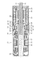
以下にまず、本発明の実施の形態に類似の構成を有する参考例を図1および図2に基づいて説明し、その後に実施例について説明する。図1,2に示す参考例において、10はハウジングで、その両端において車輪に連携されるタイロッド(図示せず)に連携されるラック軸11が貫通配置されている。このラック軸11はステアリングハンドル(図示せず)の操作トルクを伝えるピニオン軸12と所定の角度で連携されている。ハウジング10内には、電動モータ13と減速機14とが、ラック軸11に対し同軸的に配置されている。
First, a reference example having a configuration similar to that of the embodiment of the present invention will be described with reference to FIGS. 1 and 2, and then the examples will be described . In the reference example shown in FIGS. 1 and 2,
電動モータ13は、ステータ15とロータ16を備え、ステータ15はハウジング10の内周に固定され、ロータ16はハウジング10に軸受け部材としてのベアリングを介して回転可能に支承された中空のモータ出力軸17に一体に固定されている。
The
減速機14は、入力軸18と、回転体19と出力軸20とで構成される。入力軸18はモータ出力軸17の一部として構成され、電動モータ13の出力トルクを回転体19に伝える。また入力軸18の外周には、入力軸18の軸心Xに対し所定角度傾斜した軸心Yの傾斜部21が形成されており、この傾斜部21によって回転体19が軸受け部材としてのボール22を介して回転自在に支承されている。
The
回転体19は、内輪23と外輪24とで構成され、その間にボール22が介在されている。内輪23は入力軸18の傾斜部21の外周に固定されている。外輪24の軸方向の端面には、一方においてハウジング10に固定された第1歯車A1と噛み合う第2歯車A2が形成され、また他方において出力軸20に固定された第4歯車A4と噛み合う第3歯車A3が形成されている。これら第1ないし第4歯車A1ないしA4は傘歯車として形成され、第1歯車A1と第2歯車A2との噛み合い部および第3歯車A3と第4歯車A4との噛み合い部にはコロ26が介在されている。各歯車の歯形は、コロ26に適合する凹状に形成されている。コロ26は第1歯車A1と第4歯車A4側に配設されており、第1、第4歯車は凹部に位置するコロ26とで凸状歯として形成され、第2、第3歯車は、上記凸状歯と噛み合う凹状歯として構成される。
The rotating
出力軸20は、端面において第4歯車A4が形成された大径部27と、軸受け部材としてのベアリングを介してギヤハウジング10に回転自在に支承される小径部28とで構成される。小径部28の内周には、送りナット29が形成され、この送りナット29においてボール30を介してラック軸11の送りねじ部31と噛み合っている。送りナット29、ボール30およびラック軸の送りねじ部31とでボールねじ機構が構成され、このボールねじ機構により出力軸20の回転運動が直線運動に変換されることになる。
The
なお32は入力軸18の回転角を検出する回転センサーとしてのエンコーダ、33および34は左右の車輪の推力を検出する応力センサーとしての推力センサー、35はピニオン軸上に設けられたトルクセンサーとしてのハンドルセンサーである。36は電動パワーステアリング装置を制御する制御装置で、上記各センサーからの信号処理を行うインターフェース37と、制御信号を受けて各種の演算をするCPU38とドライバー39とで構成されている。制御装置36はハンドルセンサー35のトルク、左右の推力の差などによって電動モータの出力すなわちアシスト力を制御するように構成されている。
32 is an encoder as a rotation sensor that detects the rotation angle of the
以上のように構成された電動パワーステアリング装置は以下のように作動する。 Is configured electrostatic power steering apparatus having the above operates as follows.
運転者がステアリングハンドルを操作すると、操作トルクはピニオン軸12、ラック軸11、タイロッドを介して車輪に伝えられる。このとき、ピニオン軸12上に設けられたハンドルセンサー35により操作トルクが検出されると、その検出信号は制御装置36に出力され、制御装置36のCPU38の指令により電動モータ13が作動する。電動モータ13は所定の電流値で作動し、その出力は減速機14の入力軸18に伝えられ、減速機14の減速作用すなわちトルク増幅作用により、モータ出力は大幅に増幅され、出力軸20からラック軸11に伝えられる。したがって、ラック軸11は、電動パワーステアリング装置から所定のアシスト力が付与されることになり運転者は軽い操作力で必要な操作角を与えることができる。この場合、電動モータ13の出力は、減速機14の減速作用により大幅に増幅されるので小容量の電動モータでよい。
When the driver operates the steering handle, the operation torque is transmitted to the wheels via the
以下、本発明に係わる揺動型減速機13の基本動作(基本原理)について詳細に説明する。
入力軸18が回転すると、傾斜部21が揺動すなわち首を振るような運動をし、これに軸支される回転体19は、あたかも停止寸前のこまのように揺動運動をする。そして、回転体19は揺動運動をすることにより、第2歯車A2 を第1歯車A1 に、また、第3歯車A3 を第4歯車A4の週方向に夫々噛み合わせていく。すると、第2歯車A2 は、1周期の揺動運動(入力軸1の1回転)当り、第1歯車A1 との歯数差に相当する分だけ第1歯車A1 に対して回転する。すなわち、第1歯車A1 と、第2歯車A2 との間で、1段階の減速がなされる。
Hereinafter, the basic operation of the rocking
When the
ここで、第1歯車A1 の歯数を 99、第2歯車A2 の歯数を 100とした場合を考える。入力軸1が1回正回転すると、第1歯車A1 に対して第2歯車A2 は1/100だけ正回転する。第2歯車A2 の運動は、第3歯車A3 に直接伝わり、第3歯車A3 と第4歯車A4 との間でも、同様の噛み合いを行う。この場合、第3歯車A3 の歯数を 101、第4歯車A4 の歯数を100とすると、第3歯車A3 に対して第4歯車A4 は1/100だけ逆回転する。よって、第3歯車A3 と第4歯車A4 との間でも、1段階の減速がなされる。すなわち、入力軸18の回転運動が出力軸20に伝達される際に、第1、第2歯車A1 ,A2 の間と、第3、第4歯車A3 ,A4 の間とで、2段階の減速作用を受けることになる。
Consider the case where the number of teeth of the first gear A1 is 99 and the number of teeth of the second gear A2 is 100. When the input shaft 1 rotates forward once, the second gear A2 rotates forward by 1/100 with respect to the first gear A1. The movement of the second gear A2 is directly transmitted to the third gear A3, and the same meshing is performed between the third gear A3 and the fourth gear A4. In this case, assuming that the number of teeth of the third gear A3 is 101 and the number of teeth of the fourth gear A4 is 100, the fourth gear A4 rotates reversely by 1/100 with respect to the third gear A3. Therefore, one-stage deceleration is also performed between the third gear A3 and the fourth gear A4. That is, when the rotational motion of the
上記揺動型減速機の減速比をR(入力軸18が1回転したときの出力軸20の回転数)とすると、R=1−(n1 ×n3 )/(n2 ×n4 ) ……(i)
ここで、n1 :第1歯車A1 の歯数、n2 :第2歯車A2 の歯数、n3 :第3歯車A3 の歯数、n4 :第4歯車A4 の歯数で求めることができ、例えば、n1 =999,n2 =1000,n3 =1001,n4 =1000とすると、減速比R=1/ 100万(正回転)となる。
R = 1− (n1 × n3) / (n2 × n4) (i) where R is the reduction ratio of the oscillating speed reducer and R is the number of rotations of the
Where n1 is the number of teeth of the first gear A1, n2 is the number of teeth of the second gear A2, n3 is the number of teeth of the third gear A3, and n4 is the number of teeth of the fourth gear A4. If n1 = 999, n2 = 1000, n3 = 1001, and n4 = 1000, the reduction ratio R = 1 / 1,000,000 (forward rotation).
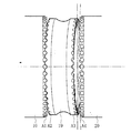
また、第2歯車A2 、第3歯車A3 が揺動運動をしながら、第1歯車A1、第4歯車A4 とそれぞれ噛み合う際には、固定歯間の各噛み合いであれば噛み合い面には摺動を生ずる。この摺動により発生する騒音、振動および発熱による焼き付きを防止する為に、各歯車の噛み合い部には、上述のように、コロ26が介在されている。したがって、図4に示すように、回転体19が周方向に揺動運動を行うと、第1歯車A1と第2歯車A2の噛み合い位置 (第3歯車A3と第4歯車の噛み合い位置 )は周方向に移動し、各凹状歯と凸状歯とを噛み合わせていく。そして、各凹状歯と凸状歯との間に生ずる摺動を、コロ26の回転で吸収している。したがって、バックラッシの設定を不要とするばかりか、各歯車間に予圧を付与して、精密な噛み合わせを行うことができる。
Further, when the second gear A2 and the third gear A3 are engaged with the first gear A1 and the fourth gear A4 while oscillating, the sliding surface is slid on the meshing surface as long as the meshing between the fixed teeth. Is produced. In order to prevent seizure due to noise, vibration and heat generated by the sliding, the
なお、前述のごとく、第1歯車A1 の歯数と第2歯車A2 の歯数差が1の場合には、揺動運動が1周期進むと、第1歯車A1 と第2歯車A2 との間で、噛み合う歯は1つずれる。また、同歯数差が2の場合は、揺動運動が1周期進むと、第1歯車A1 と第2歯車A2 との間で、噛み合う歯は2つずれる。同様にして、歯数差がnの場合には、噛み合う歯はn個ずれることになる。このことは、第3、第4歯車A3 ,A4 の関係においても同じである(なお、この種の減速機のより詳細については、本発明者の発明による特公平7-56324号公報に記載されている)。 As described above, when the difference between the number of teeth of the first gear A1 and the number of teeth of the second gear A2 is 1, when the oscillating motion advances by one cycle, the distance between the first gear A1 and the second gear A2 Thus, the teeth that mesh are shifted by one. Further, when the difference in the number of teeth is 2, when the oscillating motion advances by one period, the meshing teeth are shifted by two between the first gear A1 and the second gear A2. Similarly, when the difference in the number of teeth is n, the meshing teeth are shifted by n. This also applies to the relationship between the third and fourth gears A3 and A4 (in addition, the details of this type of reduction gear are described in Japanese Patent Publication No. 7-56324 by the inventor of the present invention. ing).
以上のごとく、本発明にかかわる揺動型減速機14は、その大きさの割りに大きなトルクを伝達することが可能であり、しかも減速比の設定についても高減速比に限られず、各歯車の外径をむやみに変更することなく、歯数差とモジュールの変更だけで高減速比から低減速比まで任意に設定できるので、電動パワーステアリング装置の車両への搭載性を損なうことなく、アシスト特性の設定の自由度が極めて拡大する。この揺動型減速機は4枚の剛性歯車により構成されるので、車輪からの高反力に対しても耐久性が高く、電動パワーステアリング装置としての信頼性を大幅に高めることができる。しかも、回転体19の軸心部は減速比に直接影響を受けることなく、半径方向内方に大径の貫通孔を確保できるので、入出力軸および出力軸と直接連携されるラック軸等の関連各部の設計の自由度が極めて向上する。
As described above, the
次に、図3に基づいて、本発明の実施例について説明する。上述した参考例と同一部分および相当部分には同一符号を付し詳細な説明を省略する。
この実施例の電動パワーステアリング装置は、電動モータ13と減速機14とがラック軸11に対し同軸的に配置されるとともにこの両者が半径方向において重合するように配置されていることを特徴とする。
Next, based on FIG. 3, it described real施例of the present invention. Parts that are the same as or equivalent to those in the reference example described above are given the same reference numerals, and detailed descriptions thereof are omitted.
The electric power steering device of the actual施例has a feature that the two are disposed so as to overlap in the radial direction together with the
具体的には、減速機14は、ハウジング10の内周面に対してベアリングを介して支承される入力軸18と、この入力軸18の内周において支承される回転体19と、出力軸20とを備える。
Specifically, the
入力軸18は中空軸として構成され、ラック軸11と同心的に支承されており、その内周面には、入力軸18の軸心Xに対し、所定角度傾斜した軸心Yを有する傾斜部21を備えている。入力軸18の傾斜部21には軸受け部材としてのボール22,22を介して、回転体19が回転自在に支承されている。
The
回転体19は、参考例と同様に、内輪23と外輪24とを備え、その間にボール22が介在されている点では同じであるが、外輪24が入力軸18の内周面に固定され、内輪側の端面に第2、第3歯車が形成されている点で相違する。したがって、回転体19は入力軸18の半径方向内方において、揺動運動すなわち首振り運動を行うことになる。また、回転体19の軸方向の端面には第2歯車A2および第3歯車A3が形成されている。第2歯車A2は、ハウジング10の端壁にボルトにて一体に固定されたスリーブ40の軸方向端面に形成された第1歯車A1と噛み合い、また、第3歯車A3は、出力軸20に一体に固定されたスリーブ41の軸方向端面に形成された第4歯車A4と噛み合うように構成されている。この各噛み合い部にはコロ26が介在されている。また、回転体19の半径方向内方には、第2および第3歯車A2,A3より内方において、軸方向に貫通する大径の貫通孔42が形成されている。
Similar to the reference example, the rotating
出力軸20は、回転体19の貫通孔42を貫通して配設されかつ第1歯車側の端部においてベアリング43を介してハウジング10に支承される小径部44と、第4歯車側においてベアリング45を介してハウジング10に支承される大径部46とで構成されている。この小径部44と大径部46とは互いに別部材として形成され、両者は、小径部44の第4歯車側の端部フランジ部において、スリーブ41の内周部端面にボルトでもって固定されることにより、一体に結合される。また、両者にはその軸心部において軸方向に貫通する連続する貫通孔が形成されている。大径部側の貫通孔には送りナット29が形成されボール30を介してラック軸11の送りねじ部31と噛み合い、出力軸20のトルクをこのボールねじ機構を介してラック軸11にアシスト力として伝えるように構成されている。また、出力軸20の小径部外周には、出力軸20の回転角を検出する回転センサーとしてのエンコーダ47が取り付けられている。
The
以上のように構成された減速機14に駆動トルクを伝える電動モータ13は、ラック軸11と同軸でかつ減速機14の半径方向外方において重合するように配設されている。この電動モータ13はコアレスモータとして構成され、ステータ15とロータ16とを備えている。ロータ16は減速機14の入力軸18に圧入嵌合されている。したがって、電動モータ13の駆動トルクは、入力軸18、回転体19、出力軸20を経由してラック軸11へと半径方向外方から内方に向かって効率よく伝えられる。
The
なお、電動モータ13の形式としては、コアとしての鉄心に巻き線を巻いた通常のタイプと、巻き線が樹脂などにより固められてコアを省略したコアレスモータとがある。実施例においては、コアレスモータを用いることにより電動パワーステアリング装置の半径方向の寸法拡大を抑制するように構成されている。つまり、コアレスモータは文字どおりステータのコアが省略されており、その分電動モータとしての半径方向の占有スペースが圧縮されることになる。
The types of the
なお、48は入力軸18の回転角を検出する回転センサーとしてのレゾルバである。
以上のように構成された実施例の電動パワーステアリング装置は、以下のような特徴がある。 Above configured real施例of the electric power steering apparatus as is characterized as follows.
まず、電動モータ13と減速機14とが、ラック軸11に対し共に同軸的に配設されると同時に両者が半径方向において重合するように配設さているので、参考例のように電動モータ13と減速機14とをラック軸11に対し軸方向において併設したものに比べ、半径方向の寸法をむやみに拡大することなく軸方向の寸法を大きく短縮することができる。
First, since the
また、入力軸18が回転体19の半径方向外方に位置することにより、回転体19の大径の貫通空間を出力軸20の専用空間として利用することができるので出力軸20の軸径の設定にあたって入力軸18によって制限を受けることなく必要径を確保することができ、しかもその軸心部において必要径のラック軸11を嵌挿することができる等、周辺関連部品の設計の自由度が向上する。
In addition, since the
特に、出力軸20を、回転体19の貫通孔42を貫通させて配置し、その両端においてハウジング10に支承することができるので、出力軸20の支持剛性が向上する。
Particularly, since the
(他の実施形態)
本発明は上記の参考例や実施例に限定されるものではなく、本発明の要旨を逸脱しない範囲で種々の変更が可能である。
(Other embodiments)
The present invention is not limited to the above reference examples and examples , and various modifications can be made without departing from the gist of the present invention.
上記参考例や実施例において、減速機による減速作用は2段階減速の例について説明したが、第1ないし第4歯車の歯数設定、傾斜部と入力軸との傾斜角度の設定によって、第1、第2歯車間による1段階のみの減速作用に限定することもでき、必要に応じて任意に設定できる。 In the above reference examples and examples, the deceleration action by the reduction gear has been described for the example of two-stage deceleration, but the first to fourth gears are set by the number of teeth, the inclination angle between the inclined portion and the input shaft is set to the first Also, it can be limited to a one-stage deceleration action between the second gears, and can be arbitrarily set as required.
また、上記参考例や実施例においては、回転体を内輪と外輪とで構成しているが、入力軸側において固定される内輪(参考例の場合)あるいは外輪(実施例の場合)を省略しボールを傾斜部で直接支持するように構成することもできる。 In the above reference examples and examples, but the rotating member is constituted by an inner ring and an outer ring, omit the inner ring (in reference example) or an outer ring which is fixed at the input shaft side (in the case of real施例) It is also possible to configure so that the ball is directly supported by the inclined portion.
11 ラック軸
13 電動モータ
14 減速機
18 入力軸
19 回転体
20 出力軸
21 傾斜部
29 送りナット
31 送りねじ軸
A1 第1歯車
A2 第2歯車
A3 第3歯車
A4 第4歯車
11 Rack axis
13 Electric motor
14 Reducer
18 Input shaft
19 Rotating body
20 Output shaft
21 Inclined part
29 Feed nut
31 Lead screw shaft
A1 1st gear
A2 Second gear
A3 3rd gear
A4 4th gear
Claims (2)
上記減速機は、上記電動モータによって駆動される入力軸と、該入力軸の外周あるいは内周に形成した傾斜部において回転自在に支承された回転体と、上記ラック軸に対して送りねじ機構によって連携される出力軸とを備え、該回転体の軸方向端部に、ハウジングに固定された歯数n1の第1歯車と噛み合う歯数n2の第2歯車と、出力軸に形成された歯数n4の第4歯車と噛み合う歯数n3の第3歯車とを形成し、上記入力軸の回転により上記回転体が揺動運動しながら各歯車間の噛み合い位置を変える揺動型減速機として構成し、
上記減速機と上記電動モータとをラック軸と同軸的に配置し、なおかつ両者を半径方向に重合するように配置したことを特徴とする電動パワーステアリング装置。 An electric power steering device comprising an electric motor and a reduction gear that decelerates rotation of the electric motor coaxially around the rack shaft,
The speed reducer includes an input shaft driven by the electric motor, a rotating body rotatably supported at an inclined portion formed on the outer periphery or inner periphery of the input shaft, and a feed screw mechanism with respect to the rack shaft. A second output gear having a number of teeth n2 meshing with a first gear having a number of teeth n1 fixed to the housing, and the number of teeth formed on the output shaft. A third gear with n3 teeth meshing with the fourth gear of n4 is formed, and is configured as an oscillating speed reducer that changes the meshing position between the gears while the rotor rotates by the rotation of the input shaft. ,
An electric power steering apparatus, wherein the speed reducer and the electric motor are arranged coaxially with a rack shaft and are arranged so as to overlap in the radial direction .
Priority Applications (1)
| Application Number | Priority Date | Filing Date | Title |
|---|---|---|---|
| JP2004273110A JP4520804B2 (en) | 2004-09-21 | 2004-09-21 | Electric power steering device |
Applications Claiming Priority (1)
| Application Number | Priority Date | Filing Date | Title |
|---|---|---|---|
| JP2004273110A JP4520804B2 (en) | 2004-09-21 | 2004-09-21 | Electric power steering device |
Related Child Applications (1)
| Application Number | Title | Priority Date | Filing Date |
|---|---|---|---|
| JP2007235463A Division JP2008030747A (en) | 2007-09-11 | 2007-09-11 | Steering device |
Publications (3)
| Publication Number | Publication Date |
|---|---|
| JP2006088726A JP2006088726A (en) | 2006-04-06 |
| JP2006088726A5 JP2006088726A5 (en) | 2007-10-25 |
| JP4520804B2 true JP4520804B2 (en) | 2010-08-11 |
Family
ID=36230125
Family Applications (1)
| Application Number | Title | Priority Date | Filing Date |
|---|---|---|---|
| JP2004273110A Expired - Lifetime JP4520804B2 (en) | 2004-09-21 | 2004-09-21 | Electric power steering device |
Country Status (1)
| Country | Link |
|---|---|
| JP (1) | JP4520804B2 (en) |
Families Citing this family (11)
| Publication number | Priority date | Publication date | Assignee | Title |
|---|---|---|---|---|
| JP4617130B2 (en) * | 2004-10-01 | 2011-01-19 | 荻野工業株式会社 | Wheel motor and reduction device |
| JP2008030747A (en) * | 2007-09-11 | 2008-02-14 | Ogino Kogyo Kk | Steering device |
| JP5234313B2 (en) * | 2007-10-22 | 2013-07-10 | 株式会社ジェイテクト | Vehicle steering system |
| US8371977B2 (en) | 2007-10-22 | 2013-02-12 | Jtekt Corporation | Transmission ratio variable mechanism and motor vehicle steering system including the same |
| JP5110361B2 (en) * | 2007-10-22 | 2012-12-26 | 株式会社ジェイテクト | Transmission ratio variable mechanism and vehicle steering apparatus including the same |
| JP5234314B2 (en) * | 2007-10-22 | 2013-07-10 | 株式会社ジェイテクト | Vehicle steering system |
| JP5110362B2 (en) * | 2007-10-22 | 2012-12-26 | 株式会社ジェイテクト | Transmission ratio variable mechanism and vehicle steering apparatus including the same |
| JP2009228784A (en) * | 2008-03-21 | 2009-10-08 | Jtekt Corp | Bearing gear |
| JP5218830B2 (en) * | 2008-06-30 | 2013-06-26 | 株式会社ジェイテクト | Vehicle steering system |
| FR3021615B1 (en) * | 2014-05-27 | 2017-12-08 | Peugeot Citroen Automobiles Sa | DIRECTION HOUSING FOR A MOTOR VEHICLE, COMPRISING AN ELECTRIC MOTOR AND A REDUCER AROUND THE TRANSVERSE AXIS |
| JP2020133761A (en) * | 2019-02-20 | 2020-08-31 | 住友重機械工業株式会社 | Drive device |
Citations (4)
| Publication number | Priority date | Publication date | Assignee | Title |
|---|---|---|---|---|
| JPS58128550A (en) * | 1982-01-26 | 1983-08-01 | Nichimen Kk | Apparatus for locking and varying power transmitting characteristics of syncline face cycloidal gear mechanism |
| JPH03149449A (en) * | 1989-11-01 | 1991-06-26 | Ichiro Kamimura | Electromotive differential type thrust generator |
| JP2000302051A (en) * | 1999-04-21 | 2000-10-31 | Aisin Seiki Co Ltd | Power steering device |
| JP2003252231A (en) * | 2002-02-28 | 2003-09-10 | Aisin Seiki Co Ltd | Rear wheel steering device for vehicle |
-
2004
- 2004-09-21 JP JP2004273110A patent/JP4520804B2/en not_active Expired - Lifetime
Patent Citations (4)
| Publication number | Priority date | Publication date | Assignee | Title |
|---|---|---|---|---|
| JPS58128550A (en) * | 1982-01-26 | 1983-08-01 | Nichimen Kk | Apparatus for locking and varying power transmitting characteristics of syncline face cycloidal gear mechanism |
| JPH03149449A (en) * | 1989-11-01 | 1991-06-26 | Ichiro Kamimura | Electromotive differential type thrust generator |
| JP2000302051A (en) * | 1999-04-21 | 2000-10-31 | Aisin Seiki Co Ltd | Power steering device |
| JP2003252231A (en) * | 2002-02-28 | 2003-09-10 | Aisin Seiki Co Ltd | Rear wheel steering device for vehicle |
Also Published As
| Publication number | Publication date |
|---|---|
| JP2006088726A (en) | 2006-04-06 |
Similar Documents
| Publication | Publication Date | Title |
|---|---|---|
| JP2008030747A (en) | Steering device | |
| JP5418834B2 (en) | Electric power steering device | |
| JP2017128250A (en) | Steering force adjustment device and steering device | |
| JP4520804B2 (en) | Electric power steering device | |
| JP2007186021A (en) | Electric power steering device | |
| JP4465240B2 (en) | Transmission gear device and vehicle steering system using the same | |
| US9114823B2 (en) | Actuating device employed in steering system for vehicle | |
| JP2006046405A5 (en) | ||
| JP2007168613A (en) | Electric power steering device | |
| JP4617130B2 (en) | Wheel motor and reduction device | |
| JP2016159668A (en) | Vehicular steering device | |
| JP2003237599A (en) | Electric power steering device | |
| JP3950695B2 (en) | Electric power steering device | |
| JP4811648B2 (en) | Electric power steering device | |
| JP2007112245A (en) | Electric power steering device | |
| JP2010144825A (en) | Vehicular steering unit | |
| JP2007216721A (en) | Electric power steering device | |
| JP2010143284A (en) | Electric power steering device | |
| JP2010285000A (en) | Electric power steering device | |
| JP5397662B2 (en) | Vehicle steering system | |
| JP3935371B2 (en) | Electric power steering device | |
| JP2010100143A (en) | Steering device for vehicle | |
| JP2005180587A (en) | Variable gear ratio mechanism and steering control device for vehicle equipped with the variable gear ratio mechanism | |
| KR100651157B1 (en) | Variable gear ratio transmission and active front wheel steering system of automobile including same | |
| JP2006205758A (en) | Electric power steering device |
Legal Events
| Date | Code | Title | Description |
|---|---|---|---|
| A521 | Request for written amendment filed |
Free format text: JAPANESE INTERMEDIATE CODE: A523 Effective date: 20070911 |
|
| A621 | Written request for application examination |
Free format text: JAPANESE INTERMEDIATE CODE: A621 Effective date: 20070911 |
|
| A131 | Notification of reasons for refusal |
Free format text: JAPANESE INTERMEDIATE CODE: A131 Effective date: 20091117 |
|
| A977 | Report on retrieval |
Free format text: JAPANESE INTERMEDIATE CODE: A971007 Effective date: 20091119 |
|
| A521 | Request for written amendment filed |
Free format text: JAPANESE INTERMEDIATE CODE: A523 Effective date: 20100113 |
|
| TRDD | Decision of grant or rejection written | ||
| A01 | Written decision to grant a patent or to grant a registration (utility model) |
Free format text: JAPANESE INTERMEDIATE CODE: A01 Effective date: 20100511 |
|
| A01 | Written decision to grant a patent or to grant a registration (utility model) |
Free format text: JAPANESE INTERMEDIATE CODE: A01 |
|
| A61 | First payment of annual fees (during grant procedure) |
Free format text: JAPANESE INTERMEDIATE CODE: A61 Effective date: 20100521 |
|
| FPAY | Renewal fee payment (event date is renewal date of database) |
Free format text: PAYMENT UNTIL: 20130528 Year of fee payment: 3 |
|
| R150 | Certificate of patent or registration of utility model |
Ref document number: 4520804 Country of ref document: JP Free format text: JAPANESE INTERMEDIATE CODE: R150 Free format text: JAPANESE INTERMEDIATE CODE: R150 |
|
| FPAY | Renewal fee payment (event date is renewal date of database) |
Free format text: PAYMENT UNTIL: 20140528 Year of fee payment: 4 |
|
| R250 | Receipt of annual fees |
Free format text: JAPANESE INTERMEDIATE CODE: R250 |
|
| R250 | Receipt of annual fees |
Free format text: JAPANESE INTERMEDIATE CODE: R250 |
|
| R250 | Receipt of annual fees |
Free format text: JAPANESE INTERMEDIATE CODE: R250 |
|
| R250 | Receipt of annual fees |
Free format text: JAPANESE INTERMEDIATE CODE: R250 |
|
| R250 | Receipt of annual fees |
Free format text: JAPANESE INTERMEDIATE CODE: R250 |
|
| R250 | Receipt of annual fees |
Free format text: JAPANESE INTERMEDIATE CODE: R250 |
|
| R250 | Receipt of annual fees |
Free format text: JAPANESE INTERMEDIATE CODE: R250 |
|
| R250 | Receipt of annual fees |
Free format text: JAPANESE INTERMEDIATE CODE: R250 |
|
| R250 | Receipt of annual fees |
Free format text: JAPANESE INTERMEDIATE CODE: R250 |
|
| R250 | Receipt of annual fees |
Free format text: JAPANESE INTERMEDIATE CODE: R250 |
|
| R250 | Receipt of annual fees |
Free format text: JAPANESE INTERMEDIATE CODE: R250 |
|
| R250 | Receipt of annual fees |
Free format text: JAPANESE INTERMEDIATE CODE: R250 |