EP1524081B1 - Spanneinrichtung mit einem Gelenkhebel - Google Patents
Spanneinrichtung mit einem Gelenkhebel Download PDFInfo
- Publication number
- EP1524081B1 EP1524081B1 EP04024245.5A EP04024245A EP1524081B1 EP 1524081 B1 EP1524081 B1 EP 1524081B1 EP 04024245 A EP04024245 A EP 04024245A EP 1524081 B1 EP1524081 B1 EP 1524081B1
- Authority
- EP
- European Patent Office
- Prior art keywords
- rod
- locking device
- sleeve
- support member
- sensors
- Prior art date
- Legal status (The legal status is an assumption and is not a legal conclusion. Google has not performed a legal analysis and makes no representation as to the accuracy of the status listed.)
- Expired - Lifetime
Links
Images




Classifications
-
- B—PERFORMING OPERATIONS; TRANSPORTING
- B25—HAND TOOLS; PORTABLE POWER-DRIVEN TOOLS; MANIPULATORS
- B25B—TOOLS OR BENCH DEVICES NOT OTHERWISE PROVIDED FOR, FOR FASTENING, CONNECTING, DISENGAGING, OR HOLDING
- B25B5/00—Clamps
- B25B5/06—Arrangements for positively actuating jaws
- B25B5/12—Arrangements for positively actuating jaws using toggle links
- B25B5/122—Arrangements for positively actuating jaws using toggle links with fluid drive
-
- B—PERFORMING OPERATIONS; TRANSPORTING
- B25—HAND TOOLS; PORTABLE POWER-DRIVEN TOOLS; MANIPULATORS
- B25B—TOOLS OR BENCH DEVICES NOT OTHERWISE PROVIDED FOR, FOR FASTENING, CONNECTING, DISENGAGING, OR HOLDING
- B25B5/00—Clamps
- B25B5/16—Details, e.g. jaws, jaw attachments
Definitions
- the present invention refers to a locking device of the articulated lever type provided with a clamping arm which can swing in order to allow to clamp workpieces with respect to the body of the device.
- a control unit for controlling the angular end-of-stroke positions of the clamping arm of such a device is known from EP-803 331 .
- This document discloses a support member for supporting a pair of sensors, typically micro-switches for example of the inductive or pneumatic type, which are removably associated to the support member in order to allow the adjustment of their mutual distance, which sensors are intended to sense the passing close to them of an appendage extending from a rod which controls the movement of the arm.
- the angular end-of-stroke positions of the clamping arm can be adjusted by changing the respective position of the sensors on the support member.
- the support member to which the sensors are associated can be inserted in a long and narrow slot extending longitudinally at the rear zone of the body of the device, in order to close sealingly the slot with the aim to prevent penetration inside the body of extraneous elements coming from the external environment.
- a locking device of the articulated lever type as per the preamble of claim 1 is known from DE-202 03 790 U1 , in which the control rod has a pair of reference means aligned along the axial direction, that move together with the control rod as a result of its sliding movement.
- a pair of sensors are fixed to the body of the device along an axial direction for sensing the passage of the reference means close to them, in order to stop the movement of the rod when it reaches respective preset end-of-stroke positions.
- the subject of the invention is a locking device having the features indicated in the claim 1.
- the locking device of the invention in addition to have a simple and reliable structure, allows to adjust the end-of-stroke positions of the clamping arm without any need to remove the sensor support member, so that the sensors are not exposed to any risk of damaging and no effect is produced on the sealing exerted by the support member with respect to the edges of the opening of the body in which it is inserted, which makes therefore the adjusting operation of the end-of-stroke of the swing of the arm at the same time much faster and simple.
- the opening in correspondence of which the support member is arranged does not have an elongated shape such as to affect a large zone of a face of the body of the device, but can have a more compact shape the extension of which is considerably smaller than that of the entire support member, so that the influence of the opening on the design requirements of the body of the device is reduced.
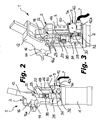
- a locking device of the articulated lever type which can be used for clamping workpieces, is indicated 1 as a whole.
- a generally fork shaped clamping arm 12 is associated to the body 2 of device 1 and is fastened to the square sectioned ends of a shaft 16 by means of U-shaped locking members 14.
- the arm 12 can swing between a preset opening position (one of which is shown by solid lines in figure 1 ) and a closing position (shown by dashed lines in the same figure).
- the shaft 16 is provided centrally by a radial control appendage 18 ( figure 3 ) having the function of a crank, which is connected by means of an articulation pin to a pair of connecting rods 23 which are in turn connected to the end of a control rod 20 slidably guided inside the body 2, by means of another articulation pin engaging a hole 20a.
- the sliding of the rod 20 is usually controlled by automatic drive means which, in the most common case, comprise a fluid-driven double acting cylinder 4, typically pneumatic, which is fixed at the bottom of the body 2.
- automatic drive means which, in the most common case, comprise a fluid-driven double acting cylinder 4, typically pneumatic, which is fixed at the bottom of the body 2.
- a coaxial sleeve 28 is slidably mounted outside the rod 20.
- a pin-shaped appendage 32 extends from the sleeve 28 towards a rear wall 3 of the body 2, transversely to the axis of the sleeve 28.
- the pin 32 is removably mounted on the sleeve 28, for example by means of a threaded connection, allowing therefore to modify the extension of its portion projecting from the sleeve itself.
- an axial through slit 30 is provided, in which another appendage 34 connected to the rod 20 and also having the shape of a pin, is guided.
- the pin 34 which is parallel to the pin 32, is preferably mounted radially and removably on the rod 20, for example by means of a threaded connection, in order to allow to change its extension with respect to the rod 20.
- the sleeve 28 is provided with fastening means adapted to fasten it selectively in a plurality of positions axially spaced along the rod 20.
- These fastening means preferably comprise a pair of threaded through holes 36, transverse to the axis of the sleeve 28 and formed at diametrically opposite zones with respect to the rod 20.
- a locking dowel screw 38 having an end provided with a hexagonal hollow seat 38a, can be engaged in each one of the holes 36.
- the seat 38a is intended to be engaged by a corresponding control wrench (not shown in the figures) which can be inserted through an opening 52 of each half-shell forming the body 2, in order to selectively fasten the sleeve 28 in one of a plurality of axial positions along the rod 20, for the purposes which will be explained in greater detail in the following.
- the openings 52 are closed by means of easy removable plugs (not shown), for example of plastic material, which can be inserted by pressure.
- Respective axial rows of seats are formed on diametrically opposite sides of the rod 20, each seat being constituted by a blind hole 40 which can be engaged by the end of the dowel screw 38 opposite to its hexagonal seat 38a, the holes 40 on a side of the rod 20 being axially offset with respect to the holes 40 of the opposite side.
- the consecutive holes 40 formed both on a side and on the opposite side of the rod 20 are axially spaced of a constant pitch, for example corresponding to a rotation of 10° of the clamping arm 12.
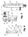
- a support member is associated to the body 2 of the device 1.
- the support member supports a pair of fixed sensors 48, 50, typically consisting of microswitches for example of the inductive, magnetic or pneumatic type, which are adapted to sense the passage in their proximity of the pins 32 and 34 as a result of the sliding of the rod 20 and the sleeve 28, in order to control the stopping of the axial sliding of the rod 20 when it reaches the end-of-stroke positions corresponding to the preset angular end-of-stroke positions of the arm 12.
- the member 5 can be fixed to the body 2 at a rectangular opening 5a formed in a rear wall 3 of the body 2 of the device 1.
- the sensors 48 and 50 are rigidly connected to a substantially L-shaped support post 46.
- the end of the less extended branch of the post 46 is fixed to a cover plate 42 having a shape corresponding to that of the opening 5a and intended to close sealingly such an opening in the assembled condition of the member 5.
- the plate 42 supports a case 42a containing the electronic control elements of the sensors 48 and 50 and, usually, a series of external LEDs for the visual signaling of their operative condition.
- An electrical connector extends from the case 42a, provided with wirings 7 to transmit pulses for controlling the operation of the cylinder 4 as a result of the operative condition of the sensors 48, 50.
- the plate is usually provided with holes 44 adapted to be engaged by locking screws (not shown) in order to allow the fixing of the plate 42 to the body 2.
- the sensors 48 and 50 are arranged on the post 46 according to positions outset sideways to each other, so that they face the directions of the axial movement of the free ends of the respective pins 32 and 36 following to the sliding of the rod 20 inside the body 2.
- the extension of the cover plate 42 in the axial direction of the rod 20 is considerably smaller of the extension of the entire support member 5, and therefore the opening 5a of the body 2 can be kept small and not much extended axially so as to affect only a small portion of the rear wall 3 of the body 2.
- the end of the post 46 opposite to the plate 42 is initially introduced in the opening 5a and, by applying a small rotation to the member 5, the post 46 is brought into a position adjacent to the wall 3 which separates it from the external environment, and the plate 42 is simultaneously arranged at the edge of the opening 5a so as to close it sealingly.
Landscapes
- Engineering & Computer Science (AREA)
- Mechanical Engineering (AREA)
- Jigs For Machine Tools (AREA)
- Mechanical Control Devices (AREA)
Claims (10)
- Spannvorrichtung vom Gelenkhebel-Typ, enthaltend eine Steuereinheit zum Steuern der Hubende-Winkelpositionen eines Spannarms, wobei der Arm (12) an einem Schaft (16) befestigt ist, welcher um eine Drehachse drehbar montiert ist, und durch eine bewegliche Gelenkhebeleinheit (22) in eine Drehung gesteuert wird als Ergebnis des axialen Gleitens einer Steuerstange (20) in Bezug zum Körper (2) der Vorrichtung (1), wobei die Steuereinheit ein Element (5) zum Tragen eines Paars von Sensoren (48, 50) enthält, welche dazu ausgelegt sind, das nah an ihnen erfolgende Passieren von mit der Steuerstange (20) verbundenen Referenzvorrichtungen (32, 34) zu erkennen, mit dem Ziel, das Stoppen des axialen Gleitens der Stange (20) in ihre Gleitrichtungen zu steuern, wenn sie entsprechende vorgegebene Hubende-Winkelpositionen des Arms (12) erreicht, wobei das Trägerelement (5) dazu ausgelegt ist, am Körper (2) der Vorrichtung an einer im hinteren Bereich (3) der Vorrichtung (1) ausgebildeten Öffnung (5a) fixiert zu werden, wobei die Sensoren (48, 50) starr mit dem Trägerelement (5) verbunden sind und die Referenzvorrichtungen ein Paar von Fortsätzen (32, 34) enthalten, die axial getrennt und mit der Stange (20) verbunden sind, wobei wenigstens (34) einer der Fortsätze (32, 34) mit einer einstellbaren Befestigungsvorrichtung (28, 36, 38, 40) verbunden ist, um ihn in einer von einer Vielzahl von Positionen entlang der Steuerstange (20) befestigen zu können,
dadurch gekennzeichnet, dass die Sensoren (48, 50) entsprechend seitlich gegeneinander versetzten Positionen angeordnet sind, und dass jeder der Fortsätze (32, 34) derart angeordnet ist, dass er sich als Ergebnis des Gleitens der Stange (20) entlang einer dem jeweiligen Sensor (48, 50) zugewandten Bewegungsrichtung bewegt. - Spannvorrichtung nach Anspruch 1, dadurch gekennzeichnet, dass die Fortsätze mit der Stange (20) verbundene entfernbare Stifte (32, 34) sind, von welchen jeder ein freies Ende hat, das in die Richtung des jeweiligen Sensors (48, 50) gerichtet ist.
- Spannvorrichtung nach Anspruch 1 oder 2, dadurch gekennzeichnet, dass das Paar von Fortsätzen einen sich von der Stange (20) erstreckenden ersten Fortsatz (32) und sich einen von einer Hülse (28) erstreckenden zweiten Fortsatz (34) umfasst, wobei die Hülse (28) koaxial außerhalb der Stange (20) und in Bezug zu dieser verschiebbar angeordnet ist, einen axialen Schlitz (30) hat, der dazu ausgelegt ist, vom ersten Fortsatz (32) durchlaufen zu werden und eine Befestigungsvorrichtung (36, 38) enthält, um sie selektiv in einer von einer Vielzahl von axialen Positionen in Bezug zur Stange (20) befestigen zu können.
- Spannvorrichtung nach Anspruch 3, dadurch gekennzeichnet, dass die Befestigungsvorrichtung zur Befestigung der Hülse ein Gegenstück (38) enthält, das quer zur Stange (20) bewegt werden kann und das ein Ende hat, das dazu ausgelegt ist, selektiv in einen von einer Vielzahl von in der Stange (20) ausgebildeten Sitzen (40) einzugreifen.
- Spannvorrichtung nach Anspruch 4, dadurch gekennzeichnet, dass die Befestigungsvorrichtung zur Befestigung der Hülse (28) ein Gegenstück (38) enthält, das an entgegengesetzten Seiten der Hülse (28) in Bezug zur Stange (20) angeordnet werden kann, und dass die Stange (20) jeweilige Serien von Sitzen (40) an Positionen hat, die denen entsprechen, an welchen das Gegenstück (38) an der Hülse (28) angeordnet werden kann, wobei in jeden Sitz (40) selektiv durch ein Ende des Gegenstücks (38) eingegriffen werden kann, wobei die Sitze (40) von jeder der Serien von Sitzen (40) axial entlang der Stange in Bezug zu den Sitzen (40) der anderen Serie von Sitzen (40) versetzt sind.
- Spannvorrichtung nach Anspruch 4 oder 5, dadurch gekennzeichnet, dass das Gegenstück (38) von außerhalb des Körpers (2) der Vorrichtung (1) durch eine jeweilige Seitenöffnung (52) des Körpers (2) gesteuert werden kann.
- Spannvorrichtung nach Anspruch 6, dadurch gekennzeichnet, dass das Gegenstück eine Verriegelungspassschraube (38) ist, die dazu ausgelegt ist, in ein entsprechendes Gewindedurchgangsloch (36) einzugreifen, das quer in der Hülse (28) gebildet ist und eine sechseckige Hohlaufnahme (38a) an seinem der Stange (20) gegenüberliegenden Ende hat, für den Eingriff eines entsprechenden Steuerschlüssels, der durch einen jeweiligen Schlitz (52) des Körpers (2) eingeführt werden kann.
- Spannvorrichtung nach einem der Ansprüche 1 bis 7, dadurch gekennzeichnet, dass das Trägerelement (5) zum Tragen der Sensoren (48, 50) eine Deckplatte (42) enthält, die dazu ausgelegt ist, die im hinteren Bereich (3) des Körpers (2) der Vorrichtung (1) gebildete Öffnung (5a) dichtend zu verschließen, und dass sich von der Deckplatte (42) eine Säule (46) zum Tragen der Sensoren (48, 50) erstreckt.
- Spannvorrichtung nach Anspruch 8, dadurch gekennzeichnet, dass die Trägersäule (46) im Wesentlichen L-förmig ist.
- Spannvorrichtung nach Anspruch 8 oder 9, dadurch gekennzeichnet, dass die Erstreckung der Deckplatte (42) in axialer Richtung der Stange (20) beträchtlich kleiner ist als die Erstreckung des Trägerelements (5), und dass die Verbindung des Trägerelements (5) mit dem Körper (2) der Vorrichtung (1) einen ersten Schritt umfasst, in welchem die Säule (46) in die Öffnung (5a) des hinteren Bereichs (3) des Körpers (2) der Vorrichtung (1) eingeführt wird, und einen zweiten Schritt, in welchem das Trägerelement (5) gedreht wird bis die Deckplatte (42) eine Position erreicht, in welcher sie die Öffnung (5a) dichtend verschließt.
Priority Applications (1)
| Application Number | Priority Date | Filing Date | Title |
|---|---|---|---|
| PL04024245T PL1524081T3 (pl) | 2003-10-16 | 2004-10-12 | Blokujące urządzenie w rodzaju dźwigni przegubowej |
Applications Claiming Priority (2)
| Application Number | Priority Date | Filing Date | Title |
|---|---|---|---|
| ITTO20030814 | 2003-10-16 | ||
| IT000814A ITTO20030814A1 (it) | 2003-10-16 | 2003-10-16 | Gruppo di controllo delle posizioni di fine corsa angolare del braccio di serraggio di un dispositivo di chiusura a leva articolata. |
Publications (3)
| Publication Number | Publication Date |
|---|---|
| EP1524081A2 EP1524081A2 (de) | 2005-04-20 |
| EP1524081A3 EP1524081A3 (de) | 2009-05-20 |
| EP1524081B1 true EP1524081B1 (de) | 2013-05-22 |
Family
ID=34362452
Family Applications (1)
| Application Number | Title | Priority Date | Filing Date |
|---|---|---|---|
| EP04024245.5A Expired - Lifetime EP1524081B1 (de) | 2003-10-16 | 2004-10-12 | Spanneinrichtung mit einem Gelenkhebel |
Country Status (4)
| Country | Link |
|---|---|
| EP (1) | EP1524081B1 (de) |
| ES (1) | ES2424351T3 (de) |
| IT (1) | ITTO20030814A1 (de) |
| PL (1) | PL1524081T3 (de) |
Cited By (1)
| Publication number | Priority date | Publication date | Assignee | Title |
|---|---|---|---|---|
| TWI635935B (zh) * | 2016-08-23 | 2018-09-21 | Smc股份有限公司 | 夾鉗裝置 |
Families Citing this family (9)
| Publication number | Priority date | Publication date | Assignee | Title |
|---|---|---|---|---|
| ITMI20061226A1 (it) * | 2006-06-26 | 2007-12-27 | Univer Spa | Dispositivo per il bloccaggio e-o la centragtuira di pezzi da lavorare con posizioni operative settabili manualmente |
| DE102009054153A1 (de) * | 2009-11-23 | 2011-05-26 | De-Sta-Co Europe Gmbh | Spannvorrichtung |
| DE102012103921A1 (de) | 2012-05-04 | 2013-11-07 | De-Sta-Co Europe Gmbh | Spannvorrichtung |
| US10625382B2 (en) | 2012-08-01 | 2020-04-21 | Delaware Capital Formation, Inc. | Toggle lever clamp |
| EP3078453B1 (de) | 2015-04-09 | 2018-04-04 | Pneumax S.p.A. | Betätigungsvorrichtung vom gelenkhebel- oder nockentyp zur genauen positionierung eines schwenkbaren arms |
| JP6434638B2 (ja) | 2015-04-09 | 2018-12-05 | ニューマックス エス.ピー.エー. | 枢動可能アームの精密位置決めのための関節式レバー又はカム型作動装置 |
| EP3116685B1 (de) | 2015-04-29 | 2017-08-30 | Pneumax S.p.A. | Betätigungsvorrichtung mit einem betätigungselement und einem messmittel zur erkennung der positionierung des betätigungselements |
| EP3299125A1 (de) * | 2016-09-27 | 2018-03-28 | UNIVER S.p.A. | Vorrichtung zum schwenken, spannen oder positionieren von werkstücken |
| EP3575035B1 (de) * | 2018-05-29 | 2022-05-11 | UNIVER S.p.A. | Pneumatisch betreibbares arbeitsgerät |
Family Cites Families (3)
| Publication number | Priority date | Publication date | Assignee | Title |
|---|---|---|---|---|
| DE19616441C1 (de) | 1996-04-25 | 1997-06-26 | Tuenkers Maschinenbau Gmbh | Kniehebelspannvorrichtung für den Karosseriebau |
| FR2780324B1 (fr) * | 1998-06-26 | 2000-08-18 | Genus Technologies | Dispositif de positionnement, de maintien ou de serrage |
| DE20203790U1 (de) | 2002-03-08 | 2002-07-18 | Tünkers Maschinenbau GmbH, 40880 Ratingen | Kniehebelspannvorrichtung |
-
2003
- 2003-10-16 IT IT000814A patent/ITTO20030814A1/it unknown
-
2004
- 2004-10-12 EP EP04024245.5A patent/EP1524081B1/de not_active Expired - Lifetime
- 2004-10-12 PL PL04024245T patent/PL1524081T3/pl unknown
- 2004-10-12 ES ES04024245T patent/ES2424351T3/es not_active Expired - Lifetime
Cited By (1)
| Publication number | Priority date | Publication date | Assignee | Title |
|---|---|---|---|---|
| TWI635935B (zh) * | 2016-08-23 | 2018-09-21 | Smc股份有限公司 | 夾鉗裝置 |
Also Published As
| Publication number | Publication date |
|---|---|
| EP1524081A3 (de) | 2009-05-20 |
| ITTO20030814A1 (it) | 2005-04-17 |
| ES2424351T3 (es) | 2013-10-01 |
| PL1524081T3 (pl) | 2013-10-31 |
| EP1524081A2 (de) | 2005-04-20 |
Similar Documents
| Publication | Publication Date | Title |
|---|---|---|
| EP1524081A2 (de) | Steuereinheit für die Steuerung der Endposition eines drehenden Spannarms einer Spanneinrichtung mit einem Gelenkhebel | |
| US4905973A (en) | Power operated clamp with externally mounted adjustable clamp arm | |
| KR100326794B1 (ko) | 조정 가능한 클램핑 조 | |
| US6220589B1 (en) | Dual action clamp | |
| US20080073823A1 (en) | Clamp structure | |
| CA2660099C (en) | Actuator levers, collets, and collet removers | |
| EP0313767B1 (de) | Spannvorrichtung | |
| US12134926B2 (en) | Control arm having adjustable length | |
| WO2016202354A1 (de) | Drehantrieb mit stellungsrückmelder und prozessventilbaueinheit | |
| US20040021260A1 (en) | Coupling device for work pieces | |
| CN106078546A (zh) | 用于可枢转臂精确定位的铰接杆型或凸轮型的致动装置 | |
| US20060169130A1 (en) | Actuator having the function of control of operation displacement | |
| EP1368161B1 (de) | Greifer mit einer verstellbaren sensoranordnung | |
| EP0798472B1 (de) | Fluidbetätigter Drehantrieb | |
| EP2548700A1 (de) | Pneumatisch betriebenes Arbeitsgerät | |
| EP1849559A1 (de) | Positionierungs- und/oder Klemmvorrichtung mit einstellbarer Öffnungsposition des Arbeitsarms | |
| CN100455864C (zh) | 与过程控制设备一起使用的夹头 | |
| EP1764469B1 (de) | Motorisch angetriebene Fenstereinheit mit schwenkbarer Öffnung | |
| US7503255B2 (en) | Squeegee device with U-shaped carriage | |
| US4778163A (en) | Air actuated clamp | |
| EP1878539B1 (de) | Klemm- und/oder Zentriervorrichtung für Werkstücke, mit manuell einstellbaren Arbeitspositionen | |
| CA1325503C (en) | Heater clamp for injection molding | |
| EP0856692A1 (de) | Vorrichtung zur Verstellung des Stössels eines Ventils | |
| EP2241402B1 (de) | Vorrichtung zum Verriegeln von Werkstücken | |
| AU783383B2 (en) | Device to move blinds or jalousies |
Legal Events
| Date | Code | Title | Description |
|---|---|---|---|
| PUAI | Public reference made under article 153(3) epc to a published international application that has entered the european phase |
Free format text: ORIGINAL CODE: 0009012 |
|
| AK | Designated contracting states |
Kind code of ref document: A2 Designated state(s): AT BE BG CH CY CZ DE DK EE ES FI FR GB GR HU IE IT LI LU MC NL PL PT RO SE SI SK TR |
|
| AX | Request for extension of the european patent |
Extension state: AL HR LT LV MK |
|
| PUAL | Search report despatched |
Free format text: ORIGINAL CODE: 0009013 |
|
| AK | Designated contracting states |
Kind code of ref document: A3 Designated state(s): AT BE BG CH CY CZ DE DK EE ES FI FR GB GR HU IE IT LI LU MC NL PL PT RO SE SI SK TR |
|
| AX | Request for extension of the european patent |
Extension state: AL HR LT LV MK |
|
| 17P | Request for examination filed |
Effective date: 20091110 |
|
| AKX | Designation fees paid |
Designated state(s): AT BE BG CH CY CZ DE DK EE ES FI FR GB GR HU IE IT LI LU MC NL PL PT RO SE SI SK TR |
|
| 17Q | First examination report despatched |
Effective date: 20101012 |
|
| GRAP | Despatch of communication of intention to grant a patent |
Free format text: ORIGINAL CODE: EPIDOSNIGR1 |
|
| GRAS | Grant fee paid |
Free format text: ORIGINAL CODE: EPIDOSNIGR3 |
|
| GRAA | (expected) grant |
Free format text: ORIGINAL CODE: 0009210 |
|
| AK | Designated contracting states |
Kind code of ref document: B1 Designated state(s): AT BE BG CH CY CZ DE DK EE ES FI FR GB GR HU IE IT LI LU MC NL PL PT RO SE SI SK TR |
|
| REG | Reference to a national code |
Ref country code: GB Ref legal event code: FG4D |
|
| REG | Reference to a national code |
Ref country code: CH Ref legal event code: EP |
|
| REG | Reference to a national code |
Ref country code: AT Ref legal event code: REF Ref document number: 612952 Country of ref document: AT Kind code of ref document: T Effective date: 20130615 |
|
| REG | Reference to a national code |
Ref country code: IE Ref legal event code: FG4D |
|
| REG | Reference to a national code |
Ref country code: DE Ref legal event code: R096 Ref document number: 602004042163 Country of ref document: DE Effective date: 20130711 |
|
| REG | Reference to a national code |
Ref country code: ES Ref legal event code: FG2A Ref document number: 2424351 Country of ref document: ES Kind code of ref document: T3 Effective date: 20131001 |
|
| PG25 | Lapsed in a contracting state [announced via postgrant information from national office to epo] |
Ref country code: PT Free format text: LAPSE BECAUSE OF FAILURE TO SUBMIT A TRANSLATION OF THE DESCRIPTION OR TO PAY THE FEE WITHIN THE PRESCRIBED TIME-LIMIT Effective date: 20130923 Ref country code: SI Free format text: LAPSE BECAUSE OF FAILURE TO SUBMIT A TRANSLATION OF THE DESCRIPTION OR TO PAY THE FEE WITHIN THE PRESCRIBED TIME-LIMIT Effective date: 20130522 Ref country code: FI Free format text: LAPSE BECAUSE OF FAILURE TO SUBMIT A TRANSLATION OF THE DESCRIPTION OR TO PAY THE FEE WITHIN THE PRESCRIBED TIME-LIMIT Effective date: 20130522 Ref country code: GR Free format text: LAPSE BECAUSE OF FAILURE TO SUBMIT A TRANSLATION OF THE DESCRIPTION OR TO PAY THE FEE WITHIN THE PRESCRIBED TIME-LIMIT Effective date: 20130823 Ref country code: SE Free format text: LAPSE BECAUSE OF FAILURE TO SUBMIT A TRANSLATION OF THE DESCRIPTION OR TO PAY THE FEE WITHIN THE PRESCRIBED TIME-LIMIT Effective date: 20130522 |
|
| REG | Reference to a national code |
Ref country code: PL Ref legal event code: T3 |
|
| REG | Reference to a national code |
Ref country code: SK Ref legal event code: T3 Ref document number: E 14653 Country of ref document: SK |
|
| REG | Reference to a national code |
Ref country code: NL Ref legal event code: VDEP Effective date: 20130522 |
|
| PG25 | Lapsed in a contracting state [announced via postgrant information from national office to epo] |
Ref country code: BG Free format text: LAPSE BECAUSE OF FAILURE TO SUBMIT A TRANSLATION OF THE DESCRIPTION OR TO PAY THE FEE WITHIN THE PRESCRIBED TIME-LIMIT Effective date: 20130822 |
|
| PG25 | Lapsed in a contracting state [announced via postgrant information from national office to epo] |
Ref country code: BE Free format text: LAPSE BECAUSE OF FAILURE TO SUBMIT A TRANSLATION OF THE DESCRIPTION OR TO PAY THE FEE WITHIN THE PRESCRIBED TIME-LIMIT Effective date: 20130522 Ref country code: EE Free format text: LAPSE BECAUSE OF FAILURE TO SUBMIT A TRANSLATION OF THE DESCRIPTION OR TO PAY THE FEE WITHIN THE PRESCRIBED TIME-LIMIT Effective date: 20130522 Ref country code: DK Free format text: LAPSE BECAUSE OF FAILURE TO SUBMIT A TRANSLATION OF THE DESCRIPTION OR TO PAY THE FEE WITHIN THE PRESCRIBED TIME-LIMIT Effective date: 20130522 |
|
| PG25 | Lapsed in a contracting state [announced via postgrant information from national office to epo] |
Ref country code: NL Free format text: LAPSE BECAUSE OF FAILURE TO SUBMIT A TRANSLATION OF THE DESCRIPTION OR TO PAY THE FEE WITHIN THE PRESCRIBED TIME-LIMIT Effective date: 20130522 Ref country code: RO Free format text: LAPSE BECAUSE OF FAILURE TO SUBMIT A TRANSLATION OF THE DESCRIPTION OR TO PAY THE FEE WITHIN THE PRESCRIBED TIME-LIMIT Effective date: 20130522 |
|
| PLBE | No opposition filed within time limit |
Free format text: ORIGINAL CODE: 0009261 |
|
| STAA | Information on the status of an ep patent application or granted ep patent |
Free format text: STATUS: NO OPPOSITION FILED WITHIN TIME LIMIT |
|
| REG | Reference to a national code |
Ref country code: HU Ref legal event code: AG4A Ref document number: E018948 Country of ref document: HU |
|
| 26N | No opposition filed |
Effective date: 20140225 |
|
| PG25 | Lapsed in a contracting state [announced via postgrant information from national office to epo] |
Ref country code: MC Free format text: LAPSE BECAUSE OF FAILURE TO SUBMIT A TRANSLATION OF THE DESCRIPTION OR TO PAY THE FEE WITHIN THE PRESCRIBED TIME-LIMIT Effective date: 20130522 |
|
| REG | Reference to a national code |
Ref country code: CH Ref legal event code: PL |
|
| REG | Reference to a national code |
Ref country code: DE Ref legal event code: R097 Ref document number: 602004042163 Country of ref document: DE Effective date: 20140225 |
|
| GBPC | Gb: european patent ceased through non-payment of renewal fee |
Effective date: 20131012 |
|
| REG | Reference to a national code |
Ref country code: SK Ref legal event code: MM4A Ref document number: E 14653 Country of ref document: SK Effective date: 20131012 |
|
| REG | Reference to a national code |
Ref country code: IE Ref legal event code: MM4A |
|
| PG25 | Lapsed in a contracting state [announced via postgrant information from national office to epo] |
Ref country code: CH Free format text: LAPSE BECAUSE OF NON-PAYMENT OF DUE FEES Effective date: 20131031 Ref country code: LI Free format text: LAPSE BECAUSE OF NON-PAYMENT OF DUE FEES Effective date: 20131031 Ref country code: GB Free format text: LAPSE BECAUSE OF NON-PAYMENT OF DUE FEES Effective date: 20131012 |
|
| REG | Reference to a national code |
Ref country code: FR Ref legal event code: ST Effective date: 20140630 |
|
| PG25 | Lapsed in a contracting state [announced via postgrant information from national office to epo] |
Ref country code: CZ Free format text: LAPSE BECAUSE OF NON-PAYMENT OF DUE FEES Effective date: 20131012 Ref country code: FR Free format text: LAPSE BECAUSE OF NON-PAYMENT OF DUE FEES Effective date: 20131031 Ref country code: SK Free format text: LAPSE BECAUSE OF NON-PAYMENT OF DUE FEES Effective date: 20131012 |
|
| PG25 | Lapsed in a contracting state [announced via postgrant information from national office to epo] |
Ref country code: HU Free format text: LAPSE BECAUSE OF NON-PAYMENT OF DUE FEES Effective date: 20131013 |
|
| PG25 | Lapsed in a contracting state [announced via postgrant information from national office to epo] |
Ref country code: IE Free format text: LAPSE BECAUSE OF NON-PAYMENT OF DUE FEES Effective date: 20131012 |
|
| REG | Reference to a national code |
Ref country code: ES Ref legal event code: FD2A Effective date: 20141107 |
|
| REG | Reference to a national code |
Ref country code: AT Ref legal event code: MM01 Ref document number: 612952 Country of ref document: AT Kind code of ref document: T Effective date: 20131012 |
|
| PG25 | Lapsed in a contracting state [announced via postgrant information from national office to epo] |
Ref country code: ES Free format text: LAPSE BECAUSE OF NON-PAYMENT OF DUE FEES Effective date: 20131013 |
|
| REG | Reference to a national code |
Ref country code: PL Ref legal event code: LAPE |
|
| PG25 | Lapsed in a contracting state [announced via postgrant information from national office to epo] |
Ref country code: PL Free format text: LAPSE BECAUSE OF NON-PAYMENT OF DUE FEES Effective date: 20131012 Ref country code: AT Free format text: LAPSE BECAUSE OF NON-PAYMENT OF DUE FEES Effective date: 20131012 |
|
| PG25 | Lapsed in a contracting state [announced via postgrant information from national office to epo] |
Ref country code: TR Free format text: LAPSE BECAUSE OF FAILURE TO SUBMIT A TRANSLATION OF THE DESCRIPTION OR TO PAY THE FEE WITHIN THE PRESCRIBED TIME-LIMIT Effective date: 20130522 Ref country code: CY Free format text: LAPSE BECAUSE OF FAILURE TO SUBMIT A TRANSLATION OF THE DESCRIPTION OR TO PAY THE FEE WITHIN THE PRESCRIBED TIME-LIMIT Effective date: 20130522 |
|
| PG25 | Lapsed in a contracting state [announced via postgrant information from national office to epo] |
Ref country code: LU Free format text: LAPSE BECAUSE OF NON-PAYMENT OF DUE FEES Effective date: 20131012 |
|
| PGFP | Annual fee paid to national office [announced via postgrant information from national office to epo] |
Ref country code: DE Payment date: 20171030 Year of fee payment: 14 |
|
| PGFP | Annual fee paid to national office [announced via postgrant information from national office to epo] |
Ref country code: IT Payment date: 20171026 Year of fee payment: 14 |
|
| REG | Reference to a national code |
Ref country code: DE Ref legal event code: R119 Ref document number: 602004042163 Country of ref document: DE |
|
| PG25 | Lapsed in a contracting state [announced via postgrant information from national office to epo] |
Ref country code: DE Free format text: LAPSE BECAUSE OF NON-PAYMENT OF DUE FEES Effective date: 20190501 |
|
| PG25 | Lapsed in a contracting state [announced via postgrant information from national office to epo] |
Ref country code: IT Free format text: LAPSE BECAUSE OF NON-PAYMENT OF DUE FEES Effective date: 20181012 |