EP1524064A1 - Structural body of railway car and joint structure for friction stir welding - Google Patents
Structural body of railway car and joint structure for friction stir welding Download PDFInfo
- Publication number
- EP1524064A1 EP1524064A1 EP04256366A EP04256366A EP1524064A1 EP 1524064 A1 EP1524064 A1 EP 1524064A1 EP 04256366 A EP04256366 A EP 04256366A EP 04256366 A EP04256366 A EP 04256366A EP 1524064 A1 EP1524064 A1 EP 1524064A1
- Authority
- EP
- European Patent Office
- Prior art keywords
- friction stir
- stir welding
- protrusion
- flat panel
- extruded shape
- Prior art date
- Legal status (The legal status is an assumption and is not a legal conclusion. Google has not performed a legal analysis and makes no representation as to the accuracy of the status listed.)
- Granted
Links
Images


Classifications
-
- B—PERFORMING OPERATIONS; TRANSPORTING
- B61—RAILWAYS
- B61D—BODY DETAILS OR KINDS OF RAILWAY VEHICLES
- B61D17/00—Construction details of vehicle bodies
- B61D17/04—Construction details of vehicle bodies with bodies of metal; with composite, e.g. metal and wood body structures
-
- B—PERFORMING OPERATIONS; TRANSPORTING
- B61—RAILWAYS
- B61D—BODY DETAILS OR KINDS OF RAILWAY VEHICLES
- B61D17/00—Construction details of vehicle bodies
- B61D17/04—Construction details of vehicle bodies with bodies of metal; with composite, e.g. metal and wood body structures
- B61D17/043—Construction details of vehicle bodies with bodies of metal; with composite, e.g. metal and wood body structures connections between superstructure sub-units
-
- B—PERFORMING OPERATIONS; TRANSPORTING
- B23—MACHINE TOOLS; METAL-WORKING NOT OTHERWISE PROVIDED FOR
- B23K—SOLDERING OR UNSOLDERING; WELDING; CLADDING OR PLATING BY SOLDERING OR WELDING; CUTTING BY APPLYING HEAT LOCALLY, e.g. FLAME CUTTING; WORKING BY LASER BEAM
- B23K20/00—Non-electric welding by applying impact or other pressure, with or without the application of heat, e.g. cladding or plating
- B23K20/12—Non-electric welding by applying impact or other pressure, with or without the application of heat, e.g. cladding or plating the heat being generated by friction; Friction welding
- B23K20/122—Non-electric welding by applying impact or other pressure, with or without the application of heat, e.g. cladding or plating the heat being generated by friction; Friction welding using a non-consumable tool, e.g. friction stir welding
-
- B—PERFORMING OPERATIONS; TRANSPORTING
- B23—MACHINE TOOLS; METAL-WORKING NOT OTHERWISE PROVIDED FOR
- B23K—SOLDERING OR UNSOLDERING; WELDING; CLADDING OR PLATING BY SOLDERING OR WELDING; CUTTING BY APPLYING HEAT LOCALLY, e.g. FLAME CUTTING; WORKING BY LASER BEAM
- B23K33/00—Specially-profiled edge portions of workpieces for making soldering or welding connections; Filling the seams formed thereby
- B23K33/004—Filling of continuous seams
-
- B—PERFORMING OPERATIONS; TRANSPORTING
- B61—RAILWAYS
- B61D—BODY DETAILS OR KINDS OF RAILWAY VEHICLES
- B61D17/00—Construction details of vehicle bodies
-
- B—PERFORMING OPERATIONS; TRANSPORTING
- B23—MACHINE TOOLS; METAL-WORKING NOT OTHERWISE PROVIDED FOR
- B23K—SOLDERING OR UNSOLDERING; WELDING; CLADDING OR PLATING BY SOLDERING OR WELDING; CUTTING BY APPLYING HEAT LOCALLY, e.g. FLAME CUTTING; WORKING BY LASER BEAM
- B23K2101/00—Articles made by soldering, welding or cutting
- B23K2101/04—Tubular or hollow articles
- B23K2101/045—Hollow panels
Definitions
- the present invention relates to a structural body of a railway car formed by joining extruded shape members or hollow shape members via friction stir welding, and further relates to a joint structure for friction stir welding suitable for application to the structural body of a railway car.
- the car body of a railway car that is, the structural body of a railway car is structured as illustrated in FIG. 4.
- a structural body 1 of a railway car is composed of side constructions 2 corresponding to both side walls of the structural body, end constructions 3 corresponding to the ends in the traveling direction of the car body, a roof construction 4 corresponding to the upper surface thereof, and an underframe 5 corresponding to the lower surface thereof.
- such a structural body 1 of a railway car is mainly formed using extruded shape members made of aluminum alloy, wherein plural extruded shape members are joined together by friction stir welding.
- Each extruded shape member forming the structural body of the railway car is composed of a flat panel portion constituting the outer surface of the car body and a rib functioning as a reinforcement member for the flat panel portion. Further, each extruded shape member is formed in a flat-panel shape, but it is also possible to adopt a hollow extruded shape member in which two flat panels are connected via trusses.
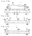
- FIGS. 5(A) through 5(C) are explanatory views showing a joint structure for friction stir welding according to the prior art.
- Two extruded shape members 10 and 20 to be joined together by friction stir welding are disposed with their joining ends butted against one another to form a joining surface 30 of a joint portion.
- a protrusion 12 that projects from the upper surface of the extruded shape member 10 toward the direction from which a tool 50 for friction stir welding is to be inserted.
- An upper surface 14 of the protrusion 12 is formed as a flat plane, and a side surface 13 of the protrusion 12 is connected to the upper surface 11 of the flat panel portion of the extruded shape member 10 via a small arc R 1 .
- a protrusion 22 is formed to the joining end of a second extruded shape member 20 that projects from the upper surface 21 of the flat panel portion.
- the upper surface 24 of the protrusion 22 is also formed as a flat plane, and the side surface 23 of the protrusion 22 is connected to the upper surface 21 of the flat panel portion of the extruded shape member 20 via a connecting portion having a small arc R 1 .
- the friction stir welding tool 50 has a small diameter portion 52 at an end thereof, the center of the small diameter portion 52 being positioned to correspond to the joining surface 30 when carrying out friction stir welding (FIG. 5(A)).
- the joint portion of the extruded members 10 and 20 being welded together has a flat surface 40 formed as the upper surface, and weld flashes B 1 remain on both sides of the flat surface 40 (FIG. 5(B)) .
- the weld flashes B 1 are then cut and removed to finish the formation of the joint portion (FIG. 5(C)).
- the upper surface 42 of the joint portion is projected than the upper surfaces 11 and 21 of the two extruded shape members 10 and 20 being joined together, by which a stepped portion is formed.
- This stepped portion constitutes a notch 41.
- the plate thickness of the flat panel portion of the extruded shape member should be reduced as much as possible in order to reduce the weight of the structural body of the railway car while assuring necessary strength. Therefore, if the plate thickness of the joining ends of the extruded shape members is the same as the plate thickness of the flat panel portion, it may not be possible to ensure sufficient strength due to the deterioration in strength at the joints. Therefore, it is considerable to increase the plate thickness at the joint portion compared to the plate thickness at the flat panel portion. Therefore, as shown in FIG.
- the object of the present invention is to provide a structural body of a railway car and a joint structure for friction stir welding suitably applied to the structural body of a railway car, that solve the problems mentioned above.
- the structural body of a railway car and the joint structure for friction stir welding comprise, as basic components, a protrusion that projects from the upper surface of the flat panel portion of the extruded shape member toward the direction from which a tool for friction stir welding is to be inserted, and a connecting portion formed between a side surface of the protrusion and the upper surface of the extruded shape member composed of an arc having a relatively large curvature formed to the surface of the extruded shape member and an arc having a relatively small curvature (smaller than the large curvature) formed near the side surface of the protrusion, wherein the extruded shape members are used as outer panels of the structural body of the railway car with the side provided with the protrusions of the shape members disposed to face the inner side of the car body.
- “Curvature” here means "radius of curvature”.
- a structural body of a railway car formed by joining plural extruded shape members via friction stir welding characterizes in that each extruded shape member subjected to friction stir welding formed of a flat panel and a rib; a protrusion is formed to a joining end of the flat panel, the protrusion projecting from an upper surface of the flat panel toward a direction from which a friction stir welding tool is to be inserted; a connecting portion is formed between a side surface of the protrusion and the upper surface of the flat panel, the connecting portion composed of an arc with a relatively large curvature formed near the upper surface of the flat panel and an arc with a relatively small curvature (smaller than the large curvature) formed near the side surface of the protrusion; wherein the extruded shape members are used as outer panels of the structural body of a railway car with the side of the extruded shape members having the protrusion facing an inner side of the car body.
- a structural body of a railway car formed by joining plural extruded shape members via friction stir welding characterizes in that each extruded shape member subjected to friction stir welding is formed of a flat panel and a rib; a protrusion is formed to a joining end of the flat panel, the protrusion projecting from an upper surface of the flat panel toward a direction from which a friction stir welding tool is to be inserted; a connecting portion is formed between a side surface of the protrusion and the upper surface of the flat panel, the connecting portion composed of an ellipse; wherein the extruded shape members are used as outer panels of the structural body of a railway car with the side of the extruded shape members having the protrusion facing an inner side of the car body.
- a structural body of a railway car formedby joining plural extruded hollow shape members via friction stir welding characterizes in that each extruded hollow shape member subj ected to friction stir welding is formed of two flat panels andtrusses; aprotrusion is formed to a joining end of at least one of the two flat panels, the protrusion projecting from an upper surface of the flat panel toward a direction from which a friction stir welding tool is to be inserted; a connecting portion is formed between a side surface of the protrusion and the upper surface of the flat panel, the connecting portion composed of an arc with a large curvature formed near the upper surface of the flat panel and an arc with a small curvature formed near the side surface of the projection; wherein the extrudedhollow shape members are used as outer panels of the structural body of a railway car with the side having the protrusion facing an inner side of the car body.
- a structural body of a railway car formed by joining plural extruded hollow shape members via friction stir welding characterizes in that each extrudedhollow shape member subj ected to friction stir welding is formedof two flat panels and trusses; a protrusion is formed to a joining end of at least one of the two flat panels, the protrusion proj ecting from an upper surface of the flat panel toward a direction from which a friction stir welding tool is to be inserted; a connecting portion formed between a side surface of the protrusion and the upper surface of the flat panel, the connecting portion composed of an ellipse; wherein the extruded hollow shape members are used as outer panels of the structural body of a railway car with the side having the protrusion facing an inner side of the car body.
- the above-mentioned extruded shape member is a hollow shape member of a structural body of a car having a structure in which two flat panels are connected via trusses, and at least the joint structure for friction stir welding disposed on the inner side of the car body is equipped with a connecting portion.
- the structural body of a railway car and the joint structure for friction stir welding according to the present invention comprises the above features, it is possible to assure a sufficient plate thickness at the joint portion, and the height di fferences between the j oining surface from which the weld flash generated during friction stir welding is removed and the upper surface of the extruded shape member are connected via an are having a large curvature. Therefore, the present structure enables to prevent concentration of stress to the area with the height differences.
- FIGS. 1(A) through 1(C) are explanatory views illustrating embodiment 1 of the present invention.
- Two extruded shape members 100 and 120 to be joined via friction stir welding are placed so that joining ends thereof are butted against one another, forming a joining surface 140 of the joint portion.
- a joining end of the first extruded shape member 100 is provided with a protrusion 110 formed to protrude from an upper surface of a flat panel portion of the extruded shape member 100 toward the direction from which a tool 50 for friction stir welding is to be inserted.
- the upper surface 114 of the protrusion 110 is formed as a flat surface, and a side surface 112 of the protrusion 110 is connected to the upper surface 102 of the flat panel portion of the extruded shape member 100 via a connecting portion having a first arc R 2 and a second arc R 3 .
- the first arc R 2 has a small curvature and the second arc R 3 has a large curvature.
- a joining end of the second extruded shape member 120 is provided with a protrusion 130 formed to protrude from an upper surface of a flat panel portion of the extruded shape member 120 toward the direction from which a tool 50 for friction stir welding is to be inserted.
- the upper surface 134 of the protrusion 130 is formed as a flat surface, and a side surface 132 of the protrusion 130 is connected to the upper surface 122 of the flat panel portion of the extruded shape member 120 via a connecting portion having a first arc R 2 and a second arc R 3 .
- the first arc R 2 has a small curvature and the second arc R 3 has a large curvature.
- These extruded shape members 100 and 120 are used as the outer panels of the structural body of the railway car, with the side having the protrusions 110 and 130 disposed to face the inner side of the car body.
- the friction stir welding tool 50 has a small diameter portion 52 formed at an end thereof, and the center of the small diameter portion 52 is placed to correspond to the joining surface 140 when performing friction stir welding (FIG. 1(B)).
- the joint portion formed between the extruded shape members 100 and 120 being joined has a flat surface 150 formed to the upper surface thereof and weld flashes B 1 formed at both ends of the flat surface 150.
- the weld flashes B 1 are cut and removed, and a joint portion is completed (FIG. 1(C)).
- the surface having the protrusions 110 and 130 is disposed to face the inner side of the car body.
- the plate thickness T excluding the joining portion between the extruded shape members 100 and 120 is set to a predetermined thickness to ensure necessary strength as the outer panel of the structural body of the railway car.
- This plate thickness T must be thick enough to ensure a plate thickness Tc of a joining portion determined considering the strength deterioration of the portion being subjected to friction stir welding, so if the flat surface having no protrusions 110 and 130 formed is disposed as the outer surface of the car body, the thickness T must be thicker than the thickness required to ensure the necessary strength as the outer plate.
- the plate thickness required to compensate for the deterioration of strength at the joining portion can be reservedby this portion. Therefore, the plate thickness T excluding the joining portion can be set to the thickness required to ensure necessary strength as the outer panel of the structural body of the railway car, and so it is possible to reduce the weight of the extruded shape members 100 and 120. In other words, the weight of the whole structural body of the railway car can be cut down.
- the appearance of the surface disposed as the outer side of the car body corresponding to the friction stir welded portion is not good when the surface having protrusions 110 and 130 of the extruded shape members 100 and 120 is positioned to face the inner side of the car body, it may be possible to provide protrusions having small heights to the surface of the extruded shape members 100 and 120 opposite to the surface having protrusions 110 and 130, which is the surface disposed as the outer side of the car body, and to remove the protruded portions after completing welding to create a smooth finished surface.
- the plate thickness Tc at the joining portion is finished so that the arc R 3 of protrusions 110 and 130 are left remaining, so that sufficient plate thickness Tc can be ensured without causing any stress concentration. Therefore, since it is not necessary to set the plate thickness T excluding the joining portions of the extruded shape members 100 and 130 to a thickness more than what is required as the outer panel of the structural member of the railway car, it becomes possible to reduce the overall weight of the structural body of the railway car.
- FIGS. 2(A) through 2 (C) are explanatory views illustrating embodiment 2 of the present invention.
- the two extruded shape members 200 and 220 to be joined via friction stir welding are placed so that joining ends thereof are butted against one another, forming a joining surface 240 of the joint portion.
- a joining end of the first extruded shape member 200 is provided with a protrusion 210 formed to protrude from an upper surface of a flat panel portion of the extruded shape member 200 toward the direction from which a tool 50 for friction stir welding is to be inserted.
- the upper surface 214 of the protrusion 210 is formed as a flat surface, and a side surface 212 of the protrusion 210 is connected to the upper surface 202 of the flat panel portion of the extruded shape member 200 via a connecting portion composed of a portion of an ellipse D 1 .
- the portion of an ellipse D 1 is formed so that the portion near the flat panel has a large curvature and the portion near the side surface 212 of the protrusion 210 has a small curvature.
- a joining end of the second extruded shape member 220 is provided with a protrusion 230 formed to protrude from an upper surface of a flat panel portion of the extruded shape member 220 toward the direction from which a tool 50 for friction stir welding is to be inserted.
- the upper surface 234 of the protrusion 230 is formed as a flat surface, and a side surface 232 of the protrusion 230 is connected to the upper surface 222 of the flat panel portion of the extruded shape member 220 via a connecting portion composed of a portion of an ellipse D 1 .
- the portion of an ellipse D 1 is formed so that the portion near the flat panel has a large curvature and the portion near the side surface 212 of the protrusion 210 has a small curvature.
- extruded shape members 200 and 220 are used as the outer panels of the structural body of the railway car, with the side having the protrusions 210 and 230 disposed to face the inner side of the car body.
- the friction stir welding tool 50 has a small diameter portion 52 formed at an end thereof, and the center of the small diameter portion 52 is placed to correspond to the joining surface 240 when performing friction stir welding (FIG. 2(B)).
- the joint portion formed between the extruded shape members 200 and 220 being joined has a flat surface 250 formed as the upper surface and weld flashes B 1 formed at both ends of the flat surface 250.
- the weld flashes B 1 are cut and removed, and the formation of a joint portion is completed (FIG. 2(C)).
- the plate thickness at the joining portion is finished so that the portions of an ellipse D 1 formed to the protrusions 210 and 230 are left to remain, so that sufficient plate thickness can be ensured without causing any stress concentration. Therefore, since it is not necessary to set the thickness of the plate thickness T excluding the joining portions of the extruded shape members 200 and 230 to more than what is required as the outer panel of the structural member of the railway car, it becomes possible to reduce the weight of the entire structural body of the railway car.
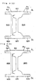
- FIGS. 3(A) through 3(D) illustrate embodiment 3 of the present invention.
- the present embodiment illustrates an example for forming a side construction of a railway car using hollow shape members made of aluminum alloy.
- a first hollow extruded shape member 400 constituting a joint portion is structured so that its cross-sectional shape is hollow, having two parallel flat panels 410 and 420 connected via trusses 460.
- a second hollow extruded shape member 500 is also structured so that its cross-sectional shape is hollow, having two parallel flat panels 510 and 520 connected via trusses 560.
- a first flat panel 410 of the first hollow extruded shape member 400 is disposed to face an inner side S 1 of the railway car body, with a protrusion 430 formed at the joining end thereof.
- a connecting portion between the protrusion 430 and the first flat panel 410 is composed of an arc R 2 having a small curvature and an arc R 3 having a large curvature, as explained in embodiment 1.
- a first flat panel 510 of the second hollow extruded shape member 500 is disposed to face an inner side S 1 of the railway car body, with a protrusion 530 formed at the joining end thereof.
- a connecting portion between the protrusion 530 and the first flat panel 510 is composed of an are R 2 having a small curvature and an are R 3 having a large curvature, as explained in embodiment 1.
- a second flat panel 420 of the first hollow extruded shape member 400 is disposed to face an outer side S 2 of the railway car body, with a protrusion 440 formed at the joining end thereof.
- the protrusion 440 and the flat panel 420 are connected via a corner portion C 1 .
- a second flat panel 520 of the second hollow extruded shape member 500 is disposed to face an outer side S 2 of the railway car body, with a protrusion 540 formed at the joining end thereof.
- the protrusion 540 and the flat panel 520 are connected via a corner portion C 2 .
- the end portions of the first hollow extruded shape member 400 and the second hollow extruded shape member 500 are engaged with one another via tapered surfaces T 1 and T 2 .
- gaps G 1 and G 2 are formed to butted portions between the first hollow member 400 and the second hollow member 500.
- Friction stir welding is carried out having the center of the small diameter portion 52 of the friction stir welding tool 50 placed to substantially correspond to the center of gaps G 1 and G 2 .
- the pressing force applied by the friction stir welding tool is mainly received by a truss 560 having high rigidity of the second hollow extruded shape member.
- FIG. 3(B) illustrates a state in which a joint surface 600 facing the inner side S 1 of the car body and a joint surface 650 facing the outer side S 2 of the car body are joined by friction stir welding.
- Weld flashes B 1 are formed on both sides of joint surfaces 600 and 650.
- FIG. 3(C) illustrates a state in which the weld flashes are removed through processing performed to the joint surface 600 facing the inner side S 1 of the car, thereby finishing a joint surface 610.
- the joint surface 610 constitutes a surface projected from the flat panel 410 of the first hollow extruded shape member and the flat panel 510 of the second hollow extruded shape member, similar to embodiment 1, and the connecting portion is connected via an arc R 3 having a large curvature, so that there will be no stress concentration. Since an interior decoration is applied to the side construction facing the inner side S 1 of the car, there is no problem even if the joint surface 610 remains protruded.
- the joint surface 610 forms a surface projected from the flat panel 410 of the first extruded hollow shape member and the flat panel 510 of the second extruded hollow shape member, it becomes possible to ensure a sufficient plate thickness at the joints, and thus there is no need to increase the thickness of the flat panels 410 and 510, so the weight of the entire structural body of the railway car can be reduced advantageously.
- FIG. 3(D) illustrates a state in which the joint surface 660 facing the outer side S 2 of the car is processed to complete a joint surface 670 forming the same plane as the flat panel 420 of the first hollow extruded shape member and the flat panel 520 of the second hollow extruded shape member.
Abstract
Description
- The present application is based on and claims priority of Japanese patent applications No. 2003-357266 filed on October 17, 2003 and No. 2004-46171 filed on February 23, 2004, the entire contents of which are hereby incorporated by reference.
- The present invention relates to a structural body of a railway car formed by joining extruded shape members or hollow shape members via friction stir welding, and further relates to a joint structure for friction stir welding suitable for application to the structural body of a railway car.
- In general, the car body of a railway car, that is, the structural body of a railway car is structured as illustrated in FIG. 4. In FIG. 4, a structural body 1 of a railway car is composed of
side constructions 2 corresponding to both side walls of the structural body,end constructions 3 corresponding to the ends in the traveling direction of the car body, aroof construction 4 corresponding to the upper surface thereof, and anunderframe 5 corresponding to the lower surface thereof. In recent years, such a structural body 1 of a railway car is mainly formed using extruded shape members made of aluminum alloy, wherein plural extruded shape members are joined together by friction stir welding. Each extruded shape member forming the structural body of the railway car is composed of a flat panel portion constituting the outer surface of the car body and a rib functioning as a reinforcement member for the flat panel portion. Further, each extruded shape member is formed in a flat-panel shape, but it is also possible to adopt a hollow extruded shape member in which two flat panels are connected via trusses. - The art of forming a structural body of a railway car via friction stir welding is disclose, for example, in Japanese Patent Publication Laid-Open No. 11-314173.
- FIGS. 5(A) through 5(C) are explanatory views showing a joint structure for friction stir welding according to the prior art.
- Two
extruded shape members surface 30 of a joint portion. - At the joining end of a first extruded
shape member 10 is formed aprotrusion 12 that projects from the upper surface of theextruded shape member 10 toward the direction from which atool 50 for friction stir welding is to be inserted. - An
upper surface 14 of theprotrusion 12 is formed as a flat plane, and a side surface 13 of theprotrusion 12 is connected to theupper surface 11 of the flat panel portion of theextruded shape member 10 via a small arc R1. - Similarly, a protrusion 22 is formed to the joining end of a second
extruded shape member 20 that projects from theupper surface 21 of the flat panel portion. Theupper surface 24 of the protrusion 22 is also formed as a flat plane, and the side surface 23 of the protrusion 22 is connected to theupper surface 21 of the flat panel portion of theextruded shape member 20 via a connecting portion having a small arc R1. - The friction
stir welding tool 50 has asmall diameter portion 52 at an end thereof, the center of thesmall diameter portion 52 being positioned to correspond to the joiningsurface 30 when carrying out friction stir welding (FIG. 5(A)). - The joint portion of the
extruded members flat surface 40 formed as the upper surface, and weld flashes B1 remain on both sides of the flat surface 40 (FIG. 5(B)) . The weld flashes B1 are then cut and removed to finish the formation of the joint portion (FIG. 5(C)). - The
upper surface 42 of the joint portion is projected than theupper surfaces extruded shape members - This stepped portion constitutes a
notch 41. - In such a joint portion, it is advantageous to increase the plate thickness compared to that of the flat panel portion, so as to compensate for the deterioration of strength at the joining portion. That is, the plate thickness of the flat panel portion of the extruded shape member should be reduced as much as possible in order to reduce the weight of the structural body of the railway car while assuring necessary strength. Therefore, if the plate thickness of the joining ends of the extruded shape members is the same as the plate thickness of the flat panel portion, it may not be possible to ensure sufficient strength due to the deterioration in strength at the joints. Therefore, it is considerable to increase the plate thickness at the joint portion compared to the plate thickness at the flat panel portion. Therefore, as shown in FIG. 5 (B), in removing the weld flashes B1 at the joint portion, portions of the
protrusions 12 and 22 are left remaining to assure the plate thickness of the joint portion as shown in FIG. 5(C). However, thenotch 41 of the protrusion remaining on the joint portion may cause stress concentration to occur when flexural stress or the like is applied to theextruded shape members - The object of the present invention is to provide a structural body of a railway car and a joint structure for friction stir welding suitably applied to the structural body of a railway car, that solve the problems mentioned above.
- In order to achieve the object, the structural body of a railway car and the joint structure for friction stir welding according to the present invention comprise, as basic components, a protrusion that projects from the upper surface of the flat panel portion of the extruded shape member toward the direction from which a tool for friction stir welding is to be inserted, and a connecting portion formed between a side surface of the protrusion and the upper surface of the extruded shape member composed of an arc having a relatively large curvature formed to the surface of the extruded shape member and an arc having a relatively small curvature (smaller than the large curvature) formed near the side surface of the protrusion, wherein the extruded shape members are used as outer panels of the structural body of the railway car with the side provided with the protrusions of the shape members disposed to face the inner side of the car body. "Curvature" here means "radius of curvature".
- According to the present invention, a structural body of a railway car formed by joining plural extruded shape members via friction stir welding characterizes in that each extruded shape member subjected to friction stir welding formed of a flat panel and a rib; a protrusion is formed to a joining end of the flat panel, the protrusion projecting from an upper surface of the flat panel toward a direction from which a friction stir welding tool is to be inserted; a connecting portion is formed between a side surface of the protrusion and the upper surface of the flat panel, the connecting portion composed of an arc with a relatively large curvature formed near the upper surface of the flat panel and an arc with a relatively small curvature (smaller than the large curvature) formed near the side surface of the protrusion; wherein the extruded shape members are used as outer panels of the structural body of a railway car with the side of the extruded shape members having the protrusion facing an inner side of the car body.
- According further to the present invention, a structural body of a railway car formed by joining plural extruded shape members via friction stir welding characterizes in that each extruded shape member subjected to friction stir welding is formed of a flat panel and a rib; a protrusion is formed to a joining end of the flat panel, the protrusion projecting from an upper surface of the flat panel toward a direction from which a friction stir welding tool is to be inserted; a connecting portion is formed between a side surface of the protrusion and the upper surface of the flat panel, the connecting portion composed of an ellipse; wherein the extruded shape members are used as outer panels of the structural body of a railway car with the side of the extruded shape members having the protrusion facing an inner side of the car body.
- According to another aspect of the present invention, a structural body of a railway car formedby joining plural extruded hollow shape members via friction stir welding characterizes in that each extruded hollow shape member subj ected to friction stir welding is formed of two flat panels andtrusses; aprotrusion is formed to a joining end of at least one of the two flat panels, the protrusion projecting from an upper surface of the flat panel toward a direction from which a friction stir welding tool is to be inserted; a connecting portion is formed between a side surface of the protrusion and the upper surface of the flat panel, the connecting portion composed of an arc with a large curvature formed near the upper surface of the flat panel and an arc with a small curvature formed near the side surface of the projection; wherein the extrudedhollow shape members are used as outer panels of the structural body of a railway car with the side having the protrusion facing an inner side of the car body.
- According to yet another aspect of the present invention, a structural body of a railway car formed by joining plural extruded hollow shape members via friction stir welding characterizes in that each extrudedhollow shape member subj ected to friction stir welding is formedof two flat panels and trusses; a protrusion is formed to a joining end of at least one of the two flat panels, the protrusion proj ecting from an upper surface of the flat panel toward a direction from which a friction stir welding tool is to be inserted; a connecting portion formed between a side surface of the protrusion and the upper surface of the flat panel, the connecting portion composed of an ellipse; wherein the extruded hollow shape members are used as outer panels of the structural body of a railway car with the side having the protrusion facing an inner side of the car body.
- According to the present invention, a joint structure for friction stir welding suitably applied to the structural body of a railway car and formed to an end of an extruded shape member to be subjected to friction stir welding comprises a protrusion projecting from an upper surface of the extruded shape member toward a direction from which a friction stir welding tool is to be inserted; and a connecting portion formed between a side surface of the protrusion and the upper surface of the extruded shape member, the connecting portion composed of an arc with a large curvature formed near the upper surface of the extruded shape member and an arc with a small curvature formed near the side surface of the projection.
- Furthermore, a joint structure for friction stir welding suitably applied to the structural body of a railway car and formed to an end of an extruded shape member to be subjected to friction stir welding comprises a protrusion projecting from an upper surface of the extruded shape member toward a direction from which a friction stir welding tool is to be inserted; and a connecting portion formed between a side surface of the protrusion and the upper surface of the extruded shape member, the connecting portion formed of an ellipse.
- Furthermore, the above-mentioned extruded shape member is a hollow shape member of a structural body of a car having a structure in which two flat panels are connected via trusses, and at least the joint structure for friction stir welding disposed on the inner side of the car body is equipped with a connecting portion.
- Since the structural body of a railway car and the joint structure for friction stir welding according to the present invention comprises the above features, it is possible to assure a sufficient plate thickness at the joint portion, and the height di fferences between the j oining surface from which the weld flash generated during friction stir welding is removed and the upper surface of the extruded shape member are connected via an are having a large curvature. Therefore, the present structure enables to prevent concentration of stress to the area with the height differences.
-
- FIG. 1 is an explanatory view showing embodiment 1 of the present invention;
- FIG. 2 is an explanatory
view showing embodiment 2 of the present invention; - FIG. 3 is an explanatory
view showing embodiment 3 of the present invention; - FIG. 4 is an explanatory view of a structural body of a railway car; and
- FIG. 5 is an explanatory view of a joint structure according to the prior art.
-
- The embodiments of the present invention will now be explained with reference to the drawings.
- FIGS. 1(A) through 1(C) are explanatory views illustrating embodiment 1 of the present invention.
- Two
extruded shape members surface 140 of the joint portion. - A joining end of the first extruded
shape member 100 is provided with aprotrusion 110 formed to protrude from an upper surface of a flat panel portion of theextruded shape member 100 toward the direction from which atool 50 for friction stir welding is to be inserted. - The
upper surface 114 of theprotrusion 110 is formed as a flat surface, and a side surface 112 of theprotrusion 110 is connected to theupper surface 102 of the flat panel portion of theextruded shape member 100 via a connecting portion having a first arc R2 and a second arc R3. The first arc R2 has a small curvature and the second arc R3 has a large curvature. - Similarly, a joining end of the second extruded
shape member 120 is provided with aprotrusion 130 formed to protrude from an upper surface of a flat panel portion of theextruded shape member 120 toward the direction from which atool 50 for friction stir welding is to be inserted. - The
upper surface 134 of theprotrusion 130 is formed as a flat surface, and aside surface 132 of theprotrusion 130 is connected to theupper surface 122 of the flat panel portion of theextruded shape member 120 via a connecting portion having a first arc R2 and a second arc R3. The first arc R2 has a small curvature and the second arc R3 has a large curvature. Theseextruded shape members protrusions - The friction
stir welding tool 50 has asmall diameter portion 52 formed at an end thereof, and the center of thesmall diameter portion 52 is placed to correspond to the joiningsurface 140 when performing friction stir welding (FIG. 1(B)). - The joint portion formed between the
extruded shape members flat surface 150 formed to the upper surface thereof and weld flashes B1 formed at both ends of theflat surface 150. The weld flashes B1 are cut and removed, and a joint portion is completed (FIG. 1(C)). - When utilizing the
extruded shape members protrusions extruded shape members protrusions protrusions shape members surface having protrusions shape members shape members surface having protrusions - According to the structure described above, the plate thickness Tc at the joining portion is finished so that the arc R3 of
protrusions shape members - FIGS. 2(A) through 2 (C) are explanatory
views illustrating embodiment 2 of the present invention. - The two extruded
shape members surface 240 of the joint portion. - A joining end of the first
extruded shape member 200 is provided with a protrusion 210 formed to protrude from an upper surface of a flat panel portion of the extrudedshape member 200 toward the direction from which atool 50 for friction stir welding is to be inserted. - The
upper surface 214 of the protrusion 210 is formed as a flat surface, and a side surface 212 of the protrusion 210 is connected to theupper surface 202 of the flat panel portion of the extrudedshape member 200 via a connecting portion composed of a portion of an ellipse D1. The portion of an ellipse D1 is formed so that the portion near the flat panel has a large curvature and the portion near the side surface 212 of the protrusion 210 has a small curvature. - Similarly, a joining end of the second
extruded shape member 220 is provided with a protrusion 230 formed to protrude from an upper surface of a flat panel portion of the extrudedshape member 220 toward the direction from which atool 50 for friction stir welding is to be inserted. - The
upper surface 234 of the protrusion 230 is formed as a flat surface, and a side surface 232 of the protrusion 230 is connected to theupper surface 222 of the flat panel portion of the extrudedshape member 220 via a connecting portion composed of a portion of an ellipse D1. The portion of an ellipse D1 is formed so that the portion near the flat panel has a large curvature and the portion near the side surface 212 of the protrusion 210 has a small curvature. - These
extruded shape members - The friction
stir welding tool 50 has asmall diameter portion 52 formed at an end thereof, and the center of thesmall diameter portion 52 is placed to correspond to the joiningsurface 240 when performing friction stir welding (FIG. 2(B)). - The joint portion formed between the
extruded shape members flat surface 250 formed as the upper surface and weld flashes B1 formed at both ends of theflat surface 250. The weld flashes B1 are cut and removed, and the formation of a joint portion is completed (FIG. 2(C)). - According to the structure described above, the plate thickness at the joining portion is finished so that the portions of an ellipse D1 formed to the protrusions 210 and 230 are left to remain, so that sufficient plate thickness can be ensured without causing any stress concentration. Therefore, since it is not necessary to set the thickness of the plate thickness T excluding the joining portions of the extruded
shape members 200 and 230 to more than what is required as the outer panel of the structural member of the railway car, it becomes possible to reduce the weight of the entire structural body of the railway car. - FIGS. 3(A) through 3(D) illustrate
embodiment 3 of the present invention. - The present embodiment illustrates an example for forming a side construction of a railway car using hollow shape members made of aluminum alloy.
- A first hollow extruded
shape member 400 constituting a joint portion is structured so that its cross-sectional shape is hollow, having two parallelflat panels trusses 460. - A second hollow extruded
shape member 500 is also structured so that its cross-sectional shape is hollow, having two parallelflat panels trusses 560. - A first
flat panel 410 of the first hollow extrudedshape member 400 is disposed to face an inner side S1 of the railway car body, with aprotrusion 430 formed at the joining end thereof. A connecting portion between theprotrusion 430 and the firstflat panel 410 is composed of an arc R2 having a small curvature and an arc R3 having a large curvature, as explained in embodiment 1. - Similarly, a first
flat panel 510 of the second hollow extrudedshape member 500 is disposed to face an inner side S1 of the railway car body, with aprotrusion 530 formed at the joining end thereof. A connecting portion between theprotrusion 530 and the firstflat panel 510 is composed of an are R2 having a small curvature and an are R3 having a large curvature, as explained in embodiment 1. - A second
flat panel 420 of the first hollow extrudedshape member 400 is disposed to face an outer side S2 of the railway car body, with aprotrusion 440 formed at the joining end thereof. Theprotrusion 440 and theflat panel 420 are connected via a corner portion C1. - A second
flat panel 520 of the second hollow extrudedshape member 500 is disposed to face an outer side S2 of the railway car body, with a protrusion 540 formed at the joining end thereof. The protrusion 540 and theflat panel 520 are connected via a corner portion C2. - The end portions of the first hollow extruded
shape member 400 and the second hollow extrudedshape member 500 are engaged with one another via tapered surfaces T1 and T2. - Thus, gaps G1 and G2 are formed to butted portions between the first
hollow member 400 and the secondhollow member 500. - Friction stir welding is carried out having the center of the
small diameter portion 52 of the frictionstir welding tool 50 placed to substantially correspond to the center of gaps G1 and G2. - During welding, the pressing force applied by the friction stir welding tool is mainly received by a
truss 560 having high rigidity of the second hollow extruded shape member. - FIG. 3(B) illustrates a state in which a joint surface 600 facing the inner side S1 of the car body and a
joint surface 650 facing the outer side S2 of the car body are joined by friction stir welding. - Weld flashes B1 are formed on both sides of
joint surfaces 600 and 650. - FIG. 3(C) illustrates a state in which the weld flashes are removed through processing performed to the joint surface 600 facing the inner side S1 of the car, thereby finishing a
joint surface 610. - The
joint surface 610 constitutes a surface projected from theflat panel 410 of the first hollow extruded shape member and theflat panel 510 of the second hollow extruded shape member, similar to embodiment 1, and the connecting portion is connected via an arc R3 having a large curvature, so that there will be no stress concentration. Since an interior decoration is applied to the side construction facing the inner side S1 of the car, there is no problem even if thejoint surface 610 remains protruded. Moreover, since thejoint surface 610 forms a surface projected from theflat panel 410 of the first extruded hollow shape member and theflat panel 510 of the second extruded hollow shape member, it becomes possible to ensure a sufficient plate thickness at the joints, and thus there is no need to increase the thickness of theflat panels - FIG. 3(D) illustrates a state in which the joint surface 660 facing the outer side S2 of the car is processed to complete a joint surface 670 forming the same plane as the
flat panel 420 of the first hollow extruded shape member and theflat panel 520 of the second hollow extruded shape member. - Since the outer side S2 of the car body is finished as a flat plane, stress concentration will not occur, and a side construction having an improved appearance can be obtained.
- Further, it is of course possible to apply the ellipse-shaped connection described in
embodiment 2 to the protrusion of the joint surface facing the inner side S1 of the car.
Claims (9)
- A structural body of a railway car formed by joining plural extruded shape members via friction stir welding, wherein:each extruded shape member subjected to friction stir welding is formed of a flat panel and a rib;a protrusion is formed to a joining end of the flat panel, the protrusion projecting from an upper surface of the flat panel toward a direction from which a friction stir welding tool is to be inserted;a connecting portion is formed between a side surface of the protrusion and the upper surface of the flat panel; the connecting portion composed of an arc with a large curvature formed near the upper surface of the flat panel and an arc with a small curvature formed near the side surface of the protrusion; andthe extruded shape members are used as outer panels of the structural body of a railway car with the surface of the extruded shape members having the protrusion facing an inner side of the car body.
- A structural body of a railway car formed by joining plural extruded shape members via friction stir welding, wherein:each extruded shape member subjected to friction stir welding is formed of a flat panel and a rib;a protrusion is formed to a joining end of the flat panel, the protrusion projecting from an upper surface of the flat panel toward a direction from which a friction stir welding tool is to be inserted;a connecting portion is formed between a side surface of the protrusion and the upper surface of the flat panel, the connecting portion composed of an ellipse; andthe extruded shape members are used as outer panels of the structural body of a railway car with the surface of the extruded shape members having the protrusion facing an inner side of the car body.
- A structural body of a railway car formed by joining plural extruded hollow shape members via friction stir welding, wherein:each extruded hollow shape member subjected to friction stir welding is formed of two flat panels and trusses;a protrusion is formed to a joining end of at least one of the two flat panels, the protrusion projecting from an upper surface of the flat panel toward a direction from which a friction stir welding tool is to be inserted;a connecting portion is formed between a side surface of the protrusion and the upper surface of the flat panel, the connecting portion composed of an arc with a large curvature formed near the upper surface of the flat panel and an arc with a small curvature formed near the side surface of the proj ection; andthe extruded hollow shape members are used as outer panels of the structural body of a railway car with the surface having the protrusion facing an inner side of the car body.
- A structural body of a railway car formed by joining plural extruded hollow shape members via friction stir welding, wherein:each extruded hollow shape member subjected to friction stir welding is formed of two flat panels and trusses;a protrusion is formed to a joining end of at least one of the two flat panels, the protrusion projecting from an upper surface of the flat panel toward a direction from which a friction stir welding tool is to be inserted;a connecting portion is formed between a side surface of the protrusion and the upper surface of the flat panel, the connecting portion composed of an ellipse; andthe extruded hollow shape members are used as outer panels of the structural body of a railway car with the surface having the protrusion facing an inner side of the car body.
- A joint structure for friction stir welding formed to an end of an extruded shape member to be subjected to friction stir welding, the joint structure comprising:aprotrusionproj ecting from an upper surface of the extruded shape member toward a direction from which a friction stir welding tool is to be inserted; anda connecting portion formed between a side surface of the protrusion and the upper surface of the extruded shape member, the connecting portion composed of an arc with a large curvature formed near the upper surface of the extruded shape member and an arc with a small curvature formed near the side surface of the projection.
- A joint structure for friction stir welding disposed to ends of extruded shape members to be' subj ected to friction stir welding, the joint structure comprising:a protrusion proj ect ing from an upper surface o f the extruded shape member toward a direction from which a friction stir welding tool is to be inserted; anda connecting portion formed between a side surface of the protrusion and the upper surface of the extruded shape member, the connecting portion composed of an ellipse.
- The joint structure for friction stir welding according to claim 5 or claim 6, wherein the extruded shape member is a flat panel.
- The joint structure for friction stir welding according to claim 5 or claim 6, wherein the extruded shape member is a hollow shape member having a structure in which two flat panels are connected via trusses.
- The joint structure for friction stir welding having the connecting portion according to claim 5 or claim 6, wherein the extruded shapemember is ahollow shape member for a structural body of a car having a structure in which two flat panels are connected via trusses.
Applications Claiming Priority (4)
| Application Number | Priority Date | Filing Date | Title |
|---|---|---|---|
| JP2003357266 | 2003-10-17 | ||
| JP2003357266A JP4291104B2 (en) | 2003-10-17 | 2003-10-17 | Friction stir welding joint structure |
| JP2004046171 | 2004-02-23 | ||
| JP2004046171A JP4610907B2 (en) | 2004-02-23 | 2004-02-23 | Railway vehicle structure |
Publications (2)
| Publication Number | Publication Date |
|---|---|
| EP1524064A1 true EP1524064A1 (en) | 2005-04-20 |
| EP1524064B1 EP1524064B1 (en) | 2010-07-14 |
Family
ID=34380428
Family Applications (1)
| Application Number | Title | Priority Date | Filing Date |
|---|---|---|---|
| EP04256366A Active EP1524064B1 (en) | 2003-10-17 | 2004-10-15 | Structural body of railway car and joint structure for friction stir welding |
Country Status (6)
| Country | Link |
|---|---|
| US (1) | US20050115456A1 (en) |
| EP (1) | EP1524064B1 (en) |
| KR (1) | KR100643254B1 (en) |
| CN (1) | CN1317153C (en) |
| AT (1) | ATE473831T1 (en) |
| DE (1) | DE602004028087D1 (en) |
Cited By (1)
| Publication number | Priority date | Publication date | Assignee | Title |
|---|---|---|---|---|
| CN102979264A (en) * | 2011-09-05 | 2013-03-20 | 片山工业株式会社 | Connected structure of pipe and mounting base |
Families Citing this family (1)
| Publication number | Priority date | Publication date | Assignee | Title |
|---|---|---|---|---|
| CN102085598B (en) * | 2009-12-03 | 2015-10-14 | 鸿富锦精密工业(深圳)有限公司 | Friction stirring connecting method |
Citations (4)
| Publication number | Priority date | Publication date | Assignee | Title |
|---|---|---|---|---|
| JPH11314173A (en) | 1996-03-19 | 1999-11-16 | Hitachi Ltd | Friction-joining method |
| US20010006710A1 (en) * | 1999-02-02 | 2001-07-05 | Takeshi Kawasaki | Hollow-shaped material |
| US20020081148A1 (en) * | 1997-07-23 | 2002-06-27 | Masakuni Ezumi | Structural body |
| US20030056459A1 (en) * | 1998-06-16 | 2003-03-27 | Masakuni Ezumi | Hollow extruded frame member for friction stir welding and structure body formed therefrom |
Family Cites Families (3)
| Publication number | Priority date | Publication date | Assignee | Title |
|---|---|---|---|---|
| JP3070735B2 (en) * | 1997-07-23 | 2000-07-31 | 株式会社日立製作所 | Friction stir welding method |
| TW464576B (en) * | 1999-05-28 | 2001-11-21 | Hitachi Ltd | A structure body and a manufacturing method of a structure body |
| CN2428151Y (en) * | 2000-06-30 | 2001-05-02 | 安泰科技股份有限公司 | Rack for insetion treatment |
-
2004
- 2004-10-15 EP EP04256366A patent/EP1524064B1/en active Active
- 2004-10-15 AT AT04256366T patent/ATE473831T1/en not_active IP Right Cessation
- 2004-10-15 CN CNB2004100903404A patent/CN1317153C/en active Active
- 2004-10-15 DE DE602004028087T patent/DE602004028087D1/en active Active
- 2004-10-15 US US10/964,692 patent/US20050115456A1/en not_active Abandoned
- 2004-10-15 KR KR1020040082457A patent/KR100643254B1/en active IP Right Grant
Patent Citations (4)
| Publication number | Priority date | Publication date | Assignee | Title |
|---|---|---|---|---|
| JPH11314173A (en) | 1996-03-19 | 1999-11-16 | Hitachi Ltd | Friction-joining method |
| US20020081148A1 (en) * | 1997-07-23 | 2002-06-27 | Masakuni Ezumi | Structural body |
| US20030056459A1 (en) * | 1998-06-16 | 2003-03-27 | Masakuni Ezumi | Hollow extruded frame member for friction stir welding and structure body formed therefrom |
| US20010006710A1 (en) * | 1999-02-02 | 2001-07-05 | Takeshi Kawasaki | Hollow-shaped material |
Cited By (2)
| Publication number | Priority date | Publication date | Assignee | Title |
|---|---|---|---|---|
| CN102979264A (en) * | 2011-09-05 | 2013-03-20 | 片山工业株式会社 | Connected structure of pipe and mounting base |
| CN102979264B (en) * | 2011-09-05 | 2016-06-08 | 片山工业株式会社 | The connected structure of tubing and mounting seat |
Also Published As
| Publication number | Publication date |
|---|---|
| CN1608784A (en) | 2005-04-27 |
| CN1317153C (en) | 2007-05-23 |
| US20050115456A1 (en) | 2005-06-02 |
| KR100643254B1 (en) | 2006-11-10 |
| DE602004028087D1 (en) | 2010-08-26 |
| ATE473831T1 (en) | 2010-07-15 |
| EP1524064B1 (en) | 2010-07-14 |
| KR20050037369A (en) | 2005-04-21 |
Similar Documents
| Publication | Publication Date | Title |
|---|---|---|
| KR100415454B1 (en) | A hollow frame member, a structure body, and a manufacturing method of a structure body | |
| US6599641B1 (en) | Structural body formed by friction stir welding of hollow extruded frame members | |
| JP3751215B2 (en) | Friction stir welding method | |
| JP2001205456A (en) | Friction stir joining method | |
| US6446562B1 (en) | Car body | |
| JP2551316B2 (en) | panel | |
| EP1213201A2 (en) | Car body of a railway car | |
| EP1524064B1 (en) | Structural body of railway car and joint structure for friction stir welding | |
| JPH0930414A (en) | Side gutter body for rail-way rolling stock | |
| JP2003025094A (en) | Structure for joining extruded-shape and product of frame assembly, using the same | |
| JPH041027Y2 (en) | ||
| JP4578985B2 (en) | Extruded hollow profile and railway vehicle structure formed by the profile | |
| JP5871361B2 (en) | Method for manufacturing a railway vehicle structure | |
| JP4440522B2 (en) | Hollow profile for friction stir welding | |
| JP4610907B2 (en) | Railway vehicle structure | |
| JP2004338601A (en) | Vehicle body structure of high-speed rolling stock | |
| JPH11311218A (en) | Joining structure of hollow panel | |
| JPH08152009A (en) | Joint structure between honeycomb panel | |
| JP2000334580A (en) | Structure and its manufacture | |
| JP3641405B2 (en) | Hollow extruded profile | |
| JP2005231576A5 (en) | ||
| JP3381682B2 (en) | Extruded panel material bonding structure | |
| JP2004025295A (en) | Assembly structure and its manufacturing method | |
| JP6909019B2 (en) | Railroad vehicle structure | |
| JP3751216B2 (en) | Hollow profile for friction stir welding |
Legal Events
| Date | Code | Title | Description |
|---|---|---|---|
| PUAI | Public reference made under article 153(3) epc to a published international application that has entered the european phase |
Free format text: ORIGINAL CODE: 0009012 |
|
| 17P | Request for examination filed |
Effective date: 20041105 |
|
| AK | Designated contracting states |
Kind code of ref document: A1 Designated state(s): AT BE BG CH CY CZ DE DK EE ES FI FR GB GR HU IE IT LI LU MC NL PL PT RO SE SI SK TR |
|
| AX | Request for extension of the european patent |
Extension state: AL HR LT LV MK |
|
| AKX | Designation fees paid |
Designated state(s): AT BE BG CH CY CZ DE DK EE ES FI FR GB GR HU IE IT LI LU MC NL PL PT RO SE SI SK TR |
|
| GRAP | Despatch of communication of intention to grant a patent |
Free format text: ORIGINAL CODE: EPIDOSNIGR1 |
|
| GRAS | Grant fee paid |
Free format text: ORIGINAL CODE: EPIDOSNIGR3 |
|
| GRAA | (expected) grant |
Free format text: ORIGINAL CODE: 0009210 |
|
| RAP1 | Party data changed (applicant data changed or rights of an application transferred) |
Owner name: HITACHI, LTD. |
|
| AK | Designated contracting states |
Kind code of ref document: B1 Designated state(s): AT BE BG CH CY CZ DE DK EE ES FI FR GB GR HU IE IT LI LU MC NL PL PT RO SE SI SK TR |
|
| REG | Reference to a national code |
Ref country code: GB Ref legal event code: FG4D |
|
| REG | Reference to a national code |
Ref country code: CH Ref legal event code: EP |
|
| RAP2 | Party data changed (patent owner data changed or rights of a patent transferred) |
Owner name: HITACHI, LTD. |
|
| REG | Reference to a national code |
Ref country code: IE Ref legal event code: FG4D |
|
| REF | Corresponds to: |
Ref document number: 602004028087 Country of ref document: DE Date of ref document: 20100826 Kind code of ref document: P |
|
| REG | Reference to a national code |
Ref country code: NL Ref legal event code: VDEP Effective date: 20100714 |
|
| PG25 | Lapsed in a contracting state [announced via postgrant information from national office to epo] |
Ref country code: NL Free format text: LAPSE BECAUSE OF FAILURE TO SUBMIT A TRANSLATION OF THE DESCRIPTION OR TO PAY THE FEE WITHIN THE PRESCRIBED TIME-LIMIT Effective date: 20100714 Ref country code: AT Free format text: LAPSE BECAUSE OF FAILURE TO SUBMIT A TRANSLATION OF THE DESCRIPTION OR TO PAY THE FEE WITHIN THE PRESCRIBED TIME-LIMIT Effective date: 20100714 Ref country code: FI Free format text: LAPSE BECAUSE OF FAILURE TO SUBMIT A TRANSLATION OF THE DESCRIPTION OR TO PAY THE FEE WITHIN THE PRESCRIBED TIME-LIMIT Effective date: 20100714 |
|
| PG25 | Lapsed in a contracting state [announced via postgrant information from national office to epo] |
Ref country code: SI Free format text: LAPSE BECAUSE OF FAILURE TO SUBMIT A TRANSLATION OF THE DESCRIPTION OR TO PAY THE FEE WITHIN THE PRESCRIBED TIME-LIMIT Effective date: 20100714 Ref country code: PL Free format text: LAPSE BECAUSE OF FAILURE TO SUBMIT A TRANSLATION OF THE DESCRIPTION OR TO PAY THE FEE WITHIN THE PRESCRIBED TIME-LIMIT Effective date: 20100714 Ref country code: CY Free format text: LAPSE BECAUSE OF FAILURE TO SUBMIT A TRANSLATION OF THE DESCRIPTION OR TO PAY THE FEE WITHIN THE PRESCRIBED TIME-LIMIT Effective date: 20100714 Ref country code: PT Free format text: LAPSE BECAUSE OF FAILURE TO SUBMIT A TRANSLATION OF THE DESCRIPTION OR TO PAY THE FEE WITHIN THE PRESCRIBED TIME-LIMIT Effective date: 20101115 Ref country code: BG Free format text: LAPSE BECAUSE OF FAILURE TO SUBMIT A TRANSLATION OF THE DESCRIPTION OR TO PAY THE FEE WITHIN THE PRESCRIBED TIME-LIMIT Effective date: 20101014 |
|
| PG25 | Lapsed in a contracting state [announced via postgrant information from national office to epo] |
Ref country code: BE Free format text: LAPSE BECAUSE OF FAILURE TO SUBMIT A TRANSLATION OF THE DESCRIPTION OR TO PAY THE FEE WITHIN THE PRESCRIBED TIME-LIMIT Effective date: 20100714 Ref country code: SE Free format text: LAPSE BECAUSE OF FAILURE TO SUBMIT A TRANSLATION OF THE DESCRIPTION OR TO PAY THE FEE WITHIN THE PRESCRIBED TIME-LIMIT Effective date: 20100714 Ref country code: GR Free format text: LAPSE BECAUSE OF FAILURE TO SUBMIT A TRANSLATION OF THE DESCRIPTION OR TO PAY THE FEE WITHIN THE PRESCRIBED TIME-LIMIT Effective date: 20101015 |
|
| PG25 | Lapsed in a contracting state [announced via postgrant information from national office to epo] |
Ref country code: DK Free format text: LAPSE BECAUSE OF FAILURE TO SUBMIT A TRANSLATION OF THE DESCRIPTION OR TO PAY THE FEE WITHIN THE PRESCRIBED TIME-LIMIT Effective date: 20100714 |
|
| PLBE | No opposition filed within time limit |
Free format text: ORIGINAL CODE: 0009261 |
|
| STAA | Information on the status of an ep patent application or granted ep patent |
Free format text: STATUS: NO OPPOSITION FILED WITHIN TIME LIMIT |
|
| PG25 | Lapsed in a contracting state [announced via postgrant information from national office to epo] |
Ref country code: RO Free format text: LAPSE BECAUSE OF FAILURE TO SUBMIT A TRANSLATION OF THE DESCRIPTION OR TO PAY THE FEE WITHIN THE PRESCRIBED TIME-LIMIT Effective date: 20100714 Ref country code: SK Free format text: LAPSE BECAUSE OF FAILURE TO SUBMIT A TRANSLATION OF THE DESCRIPTION OR TO PAY THE FEE WITHIN THE PRESCRIBED TIME-LIMIT Effective date: 20100714 Ref country code: CZ Free format text: LAPSE BECAUSE OF FAILURE TO SUBMIT A TRANSLATION OF THE DESCRIPTION OR TO PAY THE FEE WITHIN THE PRESCRIBED TIME-LIMIT Effective date: 20100714 Ref country code: MC Free format text: LAPSE BECAUSE OF NON-PAYMENT OF DUE FEES Effective date: 20101031 Ref country code: EE Free format text: LAPSE BECAUSE OF FAILURE TO SUBMIT A TRANSLATION OF THE DESCRIPTION OR TO PAY THE FEE WITHIN THE PRESCRIBED TIME-LIMIT Effective date: 20100714 Ref country code: IT Free format text: LAPSE BECAUSE OF FAILURE TO SUBMIT A TRANSLATION OF THE DESCRIPTION OR TO PAY THE FEE WITHIN THE PRESCRIBED TIME-LIMIT Effective date: 20100714 |
|
| REG | Reference to a national code |
Ref country code: CH Ref legal event code: PL |
|
| 26N | No opposition filed |
Effective date: 20110415 |
|
| PG25 | Lapsed in a contracting state [announced via postgrant information from national office to epo] |
Ref country code: ES Free format text: LAPSE BECAUSE OF FAILURE TO SUBMIT A TRANSLATION OF THE DESCRIPTION OR TO PAY THE FEE WITHIN THE PRESCRIBED TIME-LIMIT Effective date: 20101025 |
|
| REG | Reference to a national code |
Ref country code: DE Ref legal event code: R097 Ref document number: 602004028087 Country of ref document: DE Effective date: 20110415 |
|
| PG25 | Lapsed in a contracting state [announced via postgrant information from national office to epo] |
Ref country code: CH Free format text: LAPSE BECAUSE OF NON-PAYMENT OF DUE FEES Effective date: 20101031 Ref country code: LI Free format text: LAPSE BECAUSE OF NON-PAYMENT OF DUE FEES Effective date: 20101031 |
|
| PG25 | Lapsed in a contracting state [announced via postgrant information from national office to epo] |
Ref country code: IE Free format text: LAPSE BECAUSE OF NON-PAYMENT OF DUE FEES Effective date: 20101015 |
|
| PG25 | Lapsed in a contracting state [announced via postgrant information from national office to epo] |
Ref country code: HU Free format text: LAPSE BECAUSE OF FAILURE TO SUBMIT A TRANSLATION OF THE DESCRIPTION OR TO PAY THE FEE WITHIN THE PRESCRIBED TIME-LIMIT Effective date: 20110115 Ref country code: LU Free format text: LAPSE BECAUSE OF NON-PAYMENT OF DUE FEES Effective date: 20101015 |
|
| PG25 | Lapsed in a contracting state [announced via postgrant information from national office to epo] |
Ref country code: TR Free format text: LAPSE BECAUSE OF FAILURE TO SUBMIT A TRANSLATION OF THE DESCRIPTION OR TO PAY THE FEE WITHIN THE PRESCRIBED TIME-LIMIT Effective date: 20100714 |
|
| PGFP | Annual fee paid to national office [announced via postgrant information from national office to epo] |
Ref country code: FR Payment date: 20121018 Year of fee payment: 9 |
|
| REG | Reference to a national code |
Ref country code: FR Ref legal event code: ST Effective date: 20140630 |
|
| PG25 | Lapsed in a contracting state [announced via postgrant information from national office to epo] |
Ref country code: FR Free format text: LAPSE BECAUSE OF NON-PAYMENT OF DUE FEES Effective date: 20131031 |
|
| PGFP | Annual fee paid to national office [announced via postgrant information from national office to epo] |
Ref country code: GB Payment date: 20220901 Year of fee payment: 19 |
|
| PGFP | Annual fee paid to national office [announced via postgrant information from national office to epo] |
Ref country code: DE Payment date: 20220831 Year of fee payment: 19 |