EP1524061A2 - Plasma arc coating apparatus with an environmental cell having a ring with a fluid passageways and plasma arc processes for forming low oxide coatings - Google Patents
Plasma arc coating apparatus with an environmental cell having a ring with a fluid passageways and plasma arc processes for forming low oxide coatings Download PDFInfo
- Publication number
- EP1524061A2 EP1524061A2 EP04256254A EP04256254A EP1524061A2 EP 1524061 A2 EP1524061 A2 EP 1524061A2 EP 04256254 A EP04256254 A EP 04256254A EP 04256254 A EP04256254 A EP 04256254A EP 1524061 A2 EP1524061 A2 EP 1524061A2
- Authority
- EP
- European Patent Office
- Prior art keywords
- substrate
- plasma
- welding
- annular ring
- environmental cell
- Prior art date
- Legal status (The legal status is an assumption and is not a legal conclusion. Google has not performed a legal analysis and makes no representation as to the accuracy of the status listed.)
- Granted
Links
Images

Classifications
-
- B—PERFORMING OPERATIONS; TRANSPORTING
- B23—MACHINE TOOLS; METAL-WORKING NOT OTHERWISE PROVIDED FOR
- B23K—SOLDERING OR UNSOLDERING; WELDING; CLADDING OR PLATING BY SOLDERING OR WELDING; CUTTING BY APPLYING HEAT LOCALLY, e.g. FLAME CUTTING; WORKING BY LASER BEAM
- B23K10/00—Welding or cutting by means of a plasma
-
- B—PERFORMING OPERATIONS; TRANSPORTING
- B23—MACHINE TOOLS; METAL-WORKING NOT OTHERWISE PROVIDED FOR
- B23K—SOLDERING OR UNSOLDERING; WELDING; CLADDING OR PLATING BY SOLDERING OR WELDING; CUTTING BY APPLYING HEAT LOCALLY, e.g. FLAME CUTTING; WORKING BY LASER BEAM
- B23K10/00—Welding or cutting by means of a plasma
- B23K10/02—Plasma welding
- B23K10/027—Welding for purposes other than joining, e.g. build-up welding
-
- B—PERFORMING OPERATIONS; TRANSPORTING
- B23—MACHINE TOOLS; METAL-WORKING NOT OTHERWISE PROVIDED FOR
- B23K—SOLDERING OR UNSOLDERING; WELDING; CLADDING OR PLATING BY SOLDERING OR WELDING; CUTTING BY APPLYING HEAT LOCALLY, e.g. FLAME CUTTING; WORKING BY LASER BEAM
- B23K9/00—Arc welding or cutting
- B23K9/04—Welding for other purposes than joining, e.g. built-up welding
-
- B—PERFORMING OPERATIONS; TRANSPORTING
- B23—MACHINE TOOLS; METAL-WORKING NOT OTHERWISE PROVIDED FOR
- B23K—SOLDERING OR UNSOLDERING; WELDING; CLADDING OR PLATING BY SOLDERING OR WELDING; CUTTING BY APPLYING HEAT LOCALLY, e.g. FLAME CUTTING; WORKING BY LASER BEAM
- B23K9/00—Arc welding or cutting
- B23K9/04—Welding for other purposes than joining, e.g. built-up welding
- B23K9/044—Built-up welding on three-dimensional surfaces
-
- C—CHEMISTRY; METALLURGY
- C23—COATING METALLIC MATERIAL; COATING MATERIAL WITH METALLIC MATERIAL; CHEMICAL SURFACE TREATMENT; DIFFUSION TREATMENT OF METALLIC MATERIAL; COATING BY VACUUM EVAPORATION, BY SPUTTERING, BY ION IMPLANTATION OR BY CHEMICAL VAPOUR DEPOSITION, IN GENERAL; INHIBITING CORROSION OF METALLIC MATERIAL OR INCRUSTATION IN GENERAL
- C23C—COATING METALLIC MATERIAL; COATING MATERIAL WITH METALLIC MATERIAL; SURFACE TREATMENT OF METALLIC MATERIAL BY DIFFUSION INTO THE SURFACE, BY CHEMICAL CONVERSION OR SUBSTITUTION; COATING BY VACUUM EVAPORATION, BY SPUTTERING, BY ION IMPLANTATION OR BY CHEMICAL VAPOUR DEPOSITION, IN GENERAL
- C23C26/00—Coating not provided for in groups C23C2/00 - C23C24/00
- C23C26/02—Coating not provided for in groups C23C2/00 - C23C24/00 applying molten material to the substrate
-
- C—CHEMISTRY; METALLURGY
- C23—COATING METALLIC MATERIAL; COATING MATERIAL WITH METALLIC MATERIAL; CHEMICAL SURFACE TREATMENT; DIFFUSION TREATMENT OF METALLIC MATERIAL; COATING BY VACUUM EVAPORATION, BY SPUTTERING, BY ION IMPLANTATION OR BY CHEMICAL VAPOUR DEPOSITION, IN GENERAL; INHIBITING CORROSION OF METALLIC MATERIAL OR INCRUSTATION IN GENERAL
- C23C—COATING METALLIC MATERIAL; COATING MATERIAL WITH METALLIC MATERIAL; SURFACE TREATMENT OF METALLIC MATERIAL BY DIFFUSION INTO THE SURFACE, BY CHEMICAL CONVERSION OR SUBSTITUTION; COATING BY VACUUM EVAPORATION, BY SPUTTERING, BY ION IMPLANTATION OR BY CHEMICAL VAPOUR DEPOSITION, IN GENERAL
- C23C4/00—Coating by spraying the coating material in the molten state, e.g. by flame, plasma or electric discharge
- C23C4/02—Pretreatment of the material to be coated, e.g. for coating on selected surface areas
-
- F—MECHANICAL ENGINEERING; LIGHTING; HEATING; WEAPONS; BLASTING
- F01—MACHINES OR ENGINES IN GENERAL; ENGINE PLANTS IN GENERAL; STEAM ENGINES
- F01D—NON-POSITIVE DISPLACEMENT MACHINES OR ENGINES, e.g. STEAM TURBINES
- F01D5/00—Blades; Blade-carrying members; Heating, heat-insulating, cooling or antivibration means on the blades or the members
- F01D5/12—Blades
- F01D5/28—Selecting particular materials; Particular measures relating thereto; Measures against erosion or corrosion
- F01D5/288—Protective coatings for blades
-
- B—PERFORMING OPERATIONS; TRANSPORTING
- B23—MACHINE TOOLS; METAL-WORKING NOT OTHERWISE PROVIDED FOR
- B23K—SOLDERING OR UNSOLDERING; WELDING; CLADDING OR PLATING BY SOLDERING OR WELDING; CUTTING BY APPLYING HEAT LOCALLY, e.g. FLAME CUTTING; WORKING BY LASER BEAM
- B23K2101/00—Articles made by soldering, welding or cutting
- B23K2101/001—Turbines
-
- Y—GENERAL TAGGING OF NEW TECHNOLOGICAL DEVELOPMENTS; GENERAL TAGGING OF CROSS-SECTIONAL TECHNOLOGIES SPANNING OVER SEVERAL SECTIONS OF THE IPC; TECHNICAL SUBJECTS COVERED BY FORMER USPC CROSS-REFERENCE ART COLLECTIONS [XRACs] AND DIGESTS
- Y02—TECHNOLOGIES OR APPLICATIONS FOR MITIGATION OR ADAPTATION AGAINST CLIMATE CHANGE
- Y02T—CLIMATE CHANGE MITIGATION TECHNOLOGIES RELATED TO TRANSPORTATION
- Y02T50/00—Aeronautics or air transport
- Y02T50/60—Efficient propulsion technologies, e.g. for aircraft
Definitions
- the present disclosure is generally related to welding and plasma spray processes and apparatuses such as may be desirable for fabrication, restoration or repair of metal articles. More particularly, the present disclosure relates to a welding process and an apparatus for producing low oxide bond coatings as well as a method for providing a bond coat during a welding process.
- TBC thermal barrier coating
- these coating systems usually include an underlying bond coat applied directly to the superalloy substrate, and a ceramic-based overcoat applied over the bond coat.
- the coatings are applied to various superalloy surfaces, such as turbine blades and vanes, combustor liners, and combustor nozzles.
- the part is repairable, it is routed through a repair cycle that includes numerous operations.
- the repair cycle may include operations such as weld repairs to fill cracks and/or restore tip dimensions, braze repairs to fill cracks and/or restore or change a vane's class, tip repairs to restore abrasive tips, and other steps.
- the repair cycle also includes reapplication of the bond coat as well as the thermal barrier coating.
- the repair process generally includes a variety or processing steps requiring different equipment sets. For example, welding may be performed to repair the substrate using various welding equipment and processes specific to welding. The welding may be followed by application of the bond coat, which generally requires transfer of the part to be repaired to a spray cell. As such two separate operations are required for effecting a weld repair and a plasma spray coat application such as the bond coat.
- TBC TBC
- the effectiveness of a TBC system is often measured by the number of thermal cycles it can withstand before it delaminates from the substrate that it is protecting. In general, coating effectiveness decreases as the exposure temperature is increased.
- the failure of a TBC is often attributed to weaknesses or defects related in some way to the bond coat, e.g., the microstructure of the bond coat or deficiencies at the bond coat -substrate interface or the bond coat-TBC interface. Thus, carefully controlling the properties of the bond coat is important for adequate and prolonged protection to the substrate.
- a local environmental cell for a welding spray gun.
- the local environmental cell comprising an annular ring having a top surface and a bottom surface, wherein the annular ring is adapted for attachment to an outer perimeter of the spray gun; and a plurality of fluid passageways radially disposed about the annular ring comprising a plurality of openings in the bottom surface of the ring in fluid communication with a vacuum source for providing a vacuum thereto.
- a welding gun and a local environmental cell combination comprising a welding gun including a permanent electrode disposed within a housing, wherein the housing includes fluid passageways for passage of an inert gas; and a local environmental cell attached to an outer perimeter of the welding gun, the local environmental cell comprising an annular ring circumscribing the welding gun housing and having a top surface and a bottom surface, wherein the annular ring further comprises a plurality of fluid passageways radially disposed about the annular ring having a plurality of openings in the bottom surface of the ring in fluid communication with a vacuum source for providing a vacuum thereto.
- a process for welding a substrate and forming a low oxide bond coat during the welding process comprising circumferentially maintaining an inert atmosphere about an area of the substrate to be welded, wherein maintaining the inert atmosphere comprises circumferentially vacuuming about the plasma arc with a local environmental cell; welding the substrate and forming a molten pool in the area of the substrate, wherein the molten pool has a trailing edge and a leading edge; and selectively depositing a powder at the trailing edge as the molten pool is solidifying or prior to solidifying in an amount effective to form a bond coat layer on the substrate.
- a process for forming a low oxide coating comprises forming a plasma arc atop a workpiece; circumferentially vacuuming an area about the plasma arc with a local environmental cell, wherein the local environmental cell comprises an annular ring engaged with an outer perimeter of a plasma spray gun for forming the plasma arc, the annular ring comprising a plurality of fluid passageways having openings positioned above the substrate so as to vacuum particulates, non-reacted powder, ozone, and fumes from the substrate; and delivering a powder in a carrier gas to the workpiece to produce the low oxide coating.
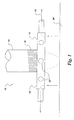
- a local environmental cell 10 for performing a welding operation such as a plasma transferred arc (PTA) or a gas tungsten arc (GTA) welding process in a controlled atmosphere.
- Welding processes such as the PTA and GTA welding processes generally flow an inert gas such as argon, helium and the like about a permanent tungsten electrode as is known in the art.
- the inert gas protects the electrode and generally shields the weld pool formed by exposing the substrate to the plasma.
- the local environmental cell 10 eliminates the need for a separate spray cell for controlling the atmosphere about the welding spray gun and as such, increases the versatility of the welding operation.
- the local environmental cell circumferentially provides a uniform vacuum about the weld pool to remove contaminants from the substrate and provide an exhaust mechanism for ozone, non-reacted powders, fumes, and the like.
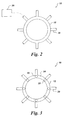
- the local environmental cell 10 generally includes an annular shaped ring 12.
- An inner diameter of the annular ring 12 is preferably threaded and sized to receive an outer diameter of a welding spray gun 14, which has a complementary threaded exterior surface 16 for threadingly engaging the annular ring 12 to the spray gun 14.
- a plurality of fluid passageways as indicated by arrow 18 is defined in the annular ring 12.
- the plurality of fluid passageways 18 comprises eight tubes 20 radially attached to an outer perimeter of the annular ring 12 and is in fluid communication with inlet openings 22 disposed in a bottom surface 24 of the ring.
- the fluid passageways 18 are preferably uniformly spaced about the annular ring 12 to provide uniform and controlled vacuuming. Although eight passageways are shown, more or less can be employed depending on the desired configuration and application. Moreover, the number of inlet openings 22 disposed in the bottom surface 24 and in fluid communication with the tubes 20 can be increased or decreased depending on the desired application.
- the ring 12 may optionally include an annular passageway (not shown) within the ring in which each fluid passageway 18 is fluidly connected therewith or alternatively, as shown, each fluid passageway 18 represents a separate passageway.
- a vacuum source 26 is fluidly connected with the passageways 18 to provide a vacuum thereto.
- the local environmental cell 10 is attached directly to the welding spray gun 20 and the vacuum openings are in close proximity to the weld pool, or substrate 30 to be coated by the plasma, the necessity of a separate spray cell employed for controlling the environment about various prior art spray applications is no longer required since the local environmental cell provides a containment center about the plasma arc and the welding pool.
- the use of the cell 10 in this manner allows the end user the opportunity to include local plasma spraying as part of the weld repair process, for example, thereby offering significant commercial advantages. More importantly, low oxide bond coatings can be formed using the spray gun in combination with the local environmental cell 10.
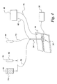
- the system 50 generally includes a plasma transferred arc torch 54, gas supplies 58, 60, a powder feed supply or hopper 62.
- the torch 54 includes a power supply 66 having one electrical lead 68 joined to the torch 54, and a second electrical lead 70 joined to the workpiece 52 for providing an electrical ground.
- Gas supply 58 is joined in fluid communication with the torch 54 using conduit 72 for supplying shielding and/or plasma gases, such as argon or a combination of argon and helium, or the like, to the torch 54 for use in developing plasma and providing a suitable shielding gas thereabout the welding pool and plasma arc.
- the local environmental cell 10 is shown disposed about an outer perimeter of torch 54 and is in fluid communication with vacuum source 26.
- the plasma gas is generally fed to an annular chamber of the torch 54 in a known manner, surrounding and insulating the electrode tip so as to form a pilot arc.
- Shielding gas is generally fed to the lower portion of the torch and distributed according to an annular path so as to substantially protect the weld pool generated during welding operations against any external chemical contaminants such as oxygen.
- the use of the local environment cell further supplements protection against external contaminants as well as removes fumes, ozone, excess powder and the like from the substrate.
- Gas supply 60 provides the carrier gas, preferably argon or nitrogen gas, to the hopper 62 for conveying the powders into the torch 54.
- the powder hopper 62 is in fluid communication with torch 54 and receives powder 74 from the powder hopper 62 and a carrier gas 76, such as argon or nitrogen, from gas supply 60 via fluid conduit 78.
- the carrier gas 76 is provided under controlled flow rate for carrying the powder 74 to the torch 54.
- the powder is generally in the form of metallic filler particulates, and for bond coat applications, can comprises Ni, Cr, Co, Bo, Fe, W, and WC, the particular selection of which depends on the desired application.
- a tubular exclusion fender or skirt typically may surround the spray gun nozzle for containing the shielding gas in the standoff volume and displacing the oxygen therefrom.
- the local environmental cell 10 is attached to the skirt.
- the shielding gas provides a temporary exclusion zone in which the plasma arc 76 is maintained and receives the injected powder for welding or cladding the workpiece 12.
- the skirt can provide a reduced oxide level in the coating, in combination with the local environmental cell 10, the presence of oxygen within the plasma environment is substantially eliminated, thereby providing the capability of depositing low oxide bond coatings as well as preventing the incorporation of oxidized powder into the bond coat. Consequently, the oxide level in the bond coating will be advantageously reduced and the density advantageously increased.
- a plasma arc is established by ionizing the argon gas passing through an electric arc formed between a permanent tungsten electrode(-) and the work piece.
- This arc is commonly referred to as the "transferred arc".
- the transferred arc is constrained by the plasma nozzle resulting in a "plasma column” with temperatures between about 10,000 °C and about 15,000 °C.
- the energy released by the arc is proportional to the amount of current applied to the arc and the arc length.
- Powdered metal is fed at a controlled rate into and /or around the plasma stream through injection ports and is subsequently heated by the arc to a molten state. The molten material is deposited onto the substrate
- the local environmental cell 10 in combination with welding spray guns provides a further reduction in oxide levels for applications requiring the deposition of a bond coat, topcoat or the like.
- the general purpose of the bond coat is to provide improved adhesion of a subsequent thermal barrier coating onto a metallic substrate.
- the bond coat for example, MCrAIY wherein M is Fe, Ni, Co, or a mixture of Ni and Co, or another metal or alloy such as hafnium and silicon or a diffusion aluminide, is applied to a superalloy substrate portion of the component, usually a nickel based or cobalt based superalloy substrate, as the first layer.
- the bond coat can provide oxidation and corrosion protection as well as being a mechanical bonding surface for the top coat.
- An example of a top coat is a thermal barrier coating that protects the metal against the action of a hot gas flow common to gas turbines.
- the thickness of the bond coat will depend on various factors, such as the oxidation protection and corrosion protection desired for the component, as well as material costs.
- the shape and size of the part may also be considered, since the thickness of the bond layer should not exceed dimensional tolerances.
- a weight limit for the part may be an additional factor for consideration (especially in the case of an airfoil), since the bond coat will add some weight to the component.
- the thickness will be in the range of about 50 microns to about 500 microns, and preferably, in the range of about 100 microns to about 400 microns. In especially preferred embodiments, the thickness will be in the range of about 200 microns to about 300 microns.
- a bond coat is simultaneously deposited during a welding process.
- the process generally comprises forming a welding pool in the substrate using the local environmental cell 10 in combination with a welding gun as previously described.
- the welding pool is in a molten state having a leading edge and a trailing edge.
- Powder suitable for forming a bond coat is selectively deposited at the trailing edge, wherein the molten pool is cooler than the leading edge.
- the powder is deposited immediately prior to solidification or simultaneously with solidification of the trailing edge. In this manner, the powder does not completely dissolve in the molten pool but forms a rough discrete bond coat layer exhibiting high tensile strength.
- the resulting bond coat is suitable for thermally spraying a TBC thereto.
- the local environmental cell 10 reduces the oxide content of the bond coating in the manner discussed above, thereby providing a dense bond coating.
- depositing the bond coat layer during welding reduces the cycle time by eliminating a separate stand alone process normally employed by thermally spraying the bond coat layer after the welding process.
Landscapes
- Engineering & Computer Science (AREA)
- Mechanical Engineering (AREA)
- Chemical & Material Sciences (AREA)
- Physics & Mathematics (AREA)
- Plasma & Fusion (AREA)
- Materials Engineering (AREA)
- Organic Chemistry (AREA)
- Chemical Kinetics & Catalysis (AREA)
- Metallurgy (AREA)
- General Engineering & Computer Science (AREA)
- Coating By Spraying Or Casting (AREA)
- Details Or Accessories Of Spraying Plant Or Apparatus (AREA)
- Application Of Or Painting With Fluid Materials (AREA)
- Arc Welding In General (AREA)
Abstract
Description
Claims (10)
- A local environmental cell (10) for a welding spray gun, comprising:an annular ring (12) having a top surface and a bottom surface (24), wherein the annular ring (12) is adapted for attachment to an outer perimeter (15) of the spray gun (14); anda plurality of fluid passageways (20) radially disposed about the annular ring (12) comprising a plurality of openings (16) in the bottom surface (24) of the ring (12) in fluid communication with a vacuum source (26) for providing a vacuum thereto.
- The local environmental cell (10) of Claim 1, wherein the plurality of fluid passageways (20) comprises a plurality of tubes having one end in fluid communication with an annular passageway contained in the annular ring (12) and an other end in fluid communication with the vacuum (26), wherein each one of the tubes is uniformly spaced apart about a perimeter of the annular ring (12).
- The local environmental cell (10) of any one of the preceding claims, wherein the plurality of fluid passageways (20) comprises a plurality of tubes having one end in fluid communication with at least one passageway extending through the annular ring (12) to the opening in the bottom surface (24) and the other end in fluid communication with the vacuum (26).
- The local environmental cell (10) of any one of the preceding claims, wherein the spray gun (14) is a plasma transferred arc torch.
- A process for welding a substrate and forming a low oxide bond coat during the welding process, the process comprising:circumferentially maintaining an inert atmosphere about an area of the substrate (52) to be welded, wherein maintaining the inert atmosphere comprises circumferentially vacuuming about a plasma arc with a local environmental cell (10);welding the substrate (52) and forming a molten pool in the area of the substrate (52), wherein the molten pool has a trailing edge and a leading edge; andselectively depositing a powder at the trailing edge as the molten pool is solidifying or prior to solidifying in an amount effective to form a bond coat layer on the substrate (52).
- The process according to Claim 5, wherein forming the molten pool comprises forming plasma in a plasma transferred arc tool (54) and exposing a portion of the substrate area to the plasma.
- The process according to Claims 5 or 6, further comprising depositing a thermal barrier coating on the bond coat in a thermal spray process.
- The process according to Claim 6, wherein forming the plasma in the plasma transferred arc tool (54) comprises forming an arc between an electrode in the plasma transferred arc tool (54) and the substrate (52), and flowing an inert gas through the arc.
- The process according to any one of the preceding claims, wherein the bond coat comprises MCrAIY, wherein M is selected from the group consisting of Fe, Ni, Co, and a mixture of Ni and Co.
- A process for forming a low oxide bond coating, comprising
forming a plasma arc atop a substrate (52);
circumferentially vacuuming an area about the plasma arc with a local environmental cell (10), wherein the local environmental cell (10) comprises an annular ring (12) engaged with an outer perimeter (15) of a plasma spray gun (14) for forming the plasma arc, the annular ring (12) comprising a plurality of fluid passageways (20) having openings positioned above the substrate (52) so as to vacuum particulates, non-reacted powder, ozone, and fumes from the substrate (52); and
delivering a powder (74) in a carrier gas to the substrate to produce the bond coating.
Applications Claiming Priority (2)
| Application Number | Priority Date | Filing Date | Title |
|---|---|---|---|
| US682228 | 1984-12-14 | ||
| US10/682,228 US6963044B2 (en) | 2003-10-08 | 2003-10-08 | Coating apparatus and processes for forming low oxide coatings |
Publications (3)
| Publication Number | Publication Date |
|---|---|
| EP1524061A2 true EP1524061A2 (en) | 2005-04-20 |
| EP1524061A3 EP1524061A3 (en) | 2005-08-03 |
| EP1524061B1 EP1524061B1 (en) | 2008-07-09 |
Family
ID=34377593
Family Applications (1)
| Application Number | Title | Priority Date | Filing Date |
|---|---|---|---|
| EP04256254A Expired - Lifetime EP1524061B1 (en) | 2003-10-08 | 2004-10-08 | Process of plasma arc welding and forming low oxide coatings using a plasma arc apparatus with a environmental cell having a ring with fluid passageways |
Country Status (5)
| Country | Link |
|---|---|
| US (1) | US6963044B2 (en) |
| EP (1) | EP1524061B1 (en) |
| JP (1) | JP4731150B2 (en) |
| CN (1) | CN100574956C (en) |
| DE (1) | DE602004014868D1 (en) |
Cited By (1)
| Publication number | Priority date | Publication date | Assignee | Title |
|---|---|---|---|---|
| WO2013083671A1 (en) * | 2011-12-09 | 2013-06-13 | Sulzer Metco Ag | Method for coating a substrate |
Families Citing this family (16)
| Publication number | Priority date | Publication date | Assignee | Title |
|---|---|---|---|---|
| US20070023402A1 (en) * | 2005-07-26 | 2007-02-01 | United Technologies Corporation | Methods for repairing workpieces using microplasma spray coating |
| WO2009020804A1 (en) * | 2007-08-06 | 2009-02-12 | Olzak James M | Method of depositing electrically conductive material onto a substrate |
| US8350181B2 (en) * | 2009-08-24 | 2013-01-08 | General Electric Company | Gas distribution ring assembly for plasma spray system |
| US8237079B2 (en) * | 2009-09-01 | 2012-08-07 | General Electric Company | Adjustable plasma spray gun |
| US9315888B2 (en) | 2009-09-01 | 2016-04-19 | General Electric Company | Nozzle insert for thermal spray gun apparatus |
| GB2486488A (en) | 2010-12-17 | 2012-06-20 | Ge Aviat Systems Ltd | Testing a transient voltage protection device |
| CN102091906B (en) * | 2010-12-22 | 2012-07-25 | 北京工业大学 | Method for repairing central slot of scraper conveyor |
| US9272360B2 (en) | 2013-03-12 | 2016-03-01 | General Electric Company | Universal plasma extension gun |
| WO2015123268A1 (en) * | 2014-02-11 | 2015-08-20 | United Technologies Corporation | System and method for applying a metallic coating |
| CN105376921A (en) * | 2015-12-11 | 2016-03-02 | 武汉科技大学 | Inner cavity powder supply tungsten needle for plasma processing |
| CN105908115B (en) * | 2016-05-07 | 2024-03-22 | 苏州市力发电子有限公司 | All-wire spraying device |
| CN106735803A (en) * | 2017-01-23 | 2017-05-31 | 宁波驰迈激光科技有限公司 | A kind of plasma arc powder surfacing rifle |
| US12145893B2 (en) | 2018-08-17 | 2024-11-19 | Rtx Corporation | Coating repair for ceramic matrix composite (CMC) substrates |
| CN110205627B (en) * | 2019-07-12 | 2023-12-08 | 江苏徐工工程机械研究院有限公司 | A flame remelting processing device for end face spray coating of ring parts |
| EP3840541A1 (en) * | 2019-12-20 | 2021-06-23 | Molecular Plasma Group SA | Improved shield for atmospheric pressure plasma jet coating deposition on a substrate |
| CN113299535B (en) * | 2021-05-21 | 2022-05-10 | 北京理工大学 | Ring-shaped generation device for core-shell powder coated with oxide shell |
Family Cites Families (38)
| Publication number | Priority date | Publication date | Assignee | Title |
|---|---|---|---|---|
| US3514567A (en) * | 1968-07-22 | 1970-05-26 | Virgil G Strang | Welding equipment |
| JPS5564964A (en) * | 1978-11-11 | 1980-05-16 | Nippon Steel Corp | Production of clad slab |
| JPS56144865A (en) * | 1980-04-10 | 1981-11-11 | Mitsubishi Heavy Ind Ltd | Surface hardening build-up welding method |
| JPS5732373A (en) | 1980-08-07 | 1982-02-22 | Mitsubishi Heavy Ind Ltd | Manufacture of composite material |
| US4496823A (en) * | 1982-11-22 | 1985-01-29 | Bob Mann & Associates Incorporated | Multiple passage conduit for fume extracting welding gun |
| JPS62187572A (en) * | 1986-02-10 | 1987-08-15 | Daido Steel Co Ltd | Overlay method |
| US4739146A (en) * | 1986-02-25 | 1988-04-19 | Metallurgical Industries, Inc. | Method for applying a weld bead to a thin section of a substrate |
| JPS62211390A (en) * | 1986-03-12 | 1987-09-17 | Hitachi Ltd | Ceramic-coated heat-resistant member and its manufacturing method |
| CN86207668U (en) * | 1986-10-14 | 1987-10-07 | 机械工业部武汉材料保护研究所 | Plasma spray welding unit for deep hole |
| US4791268A (en) | 1987-01-30 | 1988-12-13 | Hypertherm, Inc. | Arc plasma torch and method using contact starting |
| JPS6425966A (en) * | 1987-07-20 | 1989-01-27 | Nippon Kokan Kk | Low-pressure arc thermal spraying method |
| US4878953A (en) * | 1988-01-13 | 1989-11-07 | Metallurgical Industries, Inc. | Method of refurbishing cast gas turbine engine components and refurbished component |
| JPH01298145A (en) * | 1988-05-27 | 1989-12-01 | Onoda Cement Co Ltd | Thermal spraying method and device for controlling atmospheric gas in thermal spraying apparatus |
| JPH02225653A (en) * | 1989-02-23 | 1990-09-07 | Komatsu Ltd | High adhesion plasma spraying method |
| US5265689A (en) * | 1991-01-14 | 1993-11-30 | Kauffmann Ricardo M | Prosthetic device for lifting and lowering a person thereon |
| JP2962599B2 (en) | 1991-07-19 | 1999-10-12 | オリジン電気株式会社 | Plasma arc torch with fume trap and method of operating the same |
| JPH06218513A (en) * | 1993-01-27 | 1994-08-09 | Hanano Shoji Kk | Method for spraying powder release agent |
| JPH0757332B2 (en) * | 1993-03-18 | 1995-06-21 | 株式会社こあ | Moving work floor equipment for splash prevention coating and its construction method |
| FR2713952B1 (en) * | 1993-12-22 | 1996-01-12 | Air Liquide | Device and method for injecting gas for the formation of a controlled atmosphere in a confined space. |
| US5620523A (en) * | 1994-04-11 | 1997-04-15 | Canon Sales Co., Inc. | Apparatus for forming film |
| DE69529736T2 (en) | 1994-08-02 | 2003-10-16 | Komatsu Ltd., Tokio/Tokyo | METHOD FOR PRODUCING A WEAR-RESISTANT CUSHIONING LAYER AND WEAR-RESISTANT COMPOSITE MATERIAL |
| TW285746B (en) * | 1994-10-26 | 1996-09-11 | Matsushita Electric Industrial Co Ltd | |
| US5686001A (en) * | 1996-01-16 | 1997-11-11 | United Technologies Corporation | Variable polarity arc technology for the repair of coated articles |
| US5719369A (en) * | 1996-04-08 | 1998-02-17 | General Electric Company | Stress corrosion crack repair by plasma arc welding underwater welding |
| US5690844A (en) * | 1996-08-26 | 1997-11-25 | General Electric Company | Powder feed for underwater welding |
| US5882272A (en) * | 1997-09-26 | 1999-03-16 | Caterpillar Inc. | Locking differential |
| US6084196A (en) * | 1998-02-25 | 2000-07-04 | General Electric Company | Elevated-temperature, plasma-transferred arc welding of nickel-base superalloy articles |
| US6084197A (en) * | 1998-06-11 | 2000-07-04 | General Electric Company | Powder-fan plasma torch |
| US5961856A (en) * | 1998-07-10 | 1999-10-05 | General Electric Company | Deep water powder feed hopper |
| JP2001059152A (en) * | 1999-08-23 | 2001-03-06 | Mitsubishi Heavy Ind Ltd | Thermal spraying device and thermal spraying method |
| JP2001172758A (en) | 1999-12-15 | 2001-06-26 | Toshiro Ikuta | Catalyst silencer for thermal spraying gun |
| DE10009133A1 (en) | 2000-02-26 | 2001-08-30 | Volkswagen Ag | Process for laser coating a surface |
| US6265689B1 (en) | 2000-04-24 | 2001-07-24 | General Electric Company | Method of underwater cladding using a powder-fan plasma torch |
| US6390383B1 (en) * | 2000-07-31 | 2002-05-21 | General Electric Company | Staged feed robotic machine |
| JP2002331335A (en) * | 2001-05-10 | 2002-11-19 | Hanano Shoji Kk | Coating method and coating mechanism for mold release lubricant |
| JP3905724B2 (en) * | 2001-06-13 | 2007-04-18 | 三菱重工業株式会社 | Repair method for Ni-base alloy parts |
| US6761776B2 (en) | 2001-12-06 | 2004-07-13 | Paul B. Bowlin | Torch cutter exhaust system |
| JP3881895B2 (en) * | 2002-01-18 | 2007-02-14 | 三菱重工業株式会社 | Plasma spraying equipment |
-
2003
- 2003-10-08 US US10/682,228 patent/US6963044B2/en not_active Expired - Lifetime
-
2004
- 2004-09-30 CN CN200410090002A patent/CN100574956C/en not_active Expired - Fee Related
- 2004-10-07 JP JP2004294835A patent/JP4731150B2/en not_active Expired - Fee Related
- 2004-10-08 DE DE602004014868T patent/DE602004014868D1/en not_active Expired - Lifetime
- 2004-10-08 EP EP04256254A patent/EP1524061B1/en not_active Expired - Lifetime
Cited By (1)
| Publication number | Priority date | Publication date | Assignee | Title |
|---|---|---|---|---|
| WO2013083671A1 (en) * | 2011-12-09 | 2013-06-13 | Sulzer Metco Ag | Method for coating a substrate |
Also Published As
| Publication number | Publication date |
|---|---|
| DE602004014868D1 (en) | 2008-08-21 |
| EP1524061A3 (en) | 2005-08-03 |
| CN100574956C (en) | 2009-12-30 |
| US20050077272A1 (en) | 2005-04-14 |
| US6963044B2 (en) | 2005-11-08 |
| JP2005146413A (en) | 2005-06-09 |
| EP1524061B1 (en) | 2008-07-09 |
| JP4731150B2 (en) | 2011-07-20 |
| CN1611318A (en) | 2005-05-04 |
Similar Documents
| Publication | Publication Date | Title |
|---|---|---|
| US6963044B2 (en) | Coating apparatus and processes for forming low oxide coatings | |
| US6302318B1 (en) | Method of providing wear-resistant coatings, and related articles | |
| US6637643B2 (en) | Method of applying a bond coating and a thermal barrier coating on a metal substrate, and related articles | |
| Tucker Jr | Thermal spray coatings | |
| US6575349B2 (en) | Method of applying braze materials to a substrate | |
| US5019429A (en) | High density thermal spray coating and process | |
| US6355356B1 (en) | Coating system for providing environmental protection to a metal substrate, and related processes | |
| EP1550735B1 (en) | Method of forming metal coating with hvof spray gun and thermal spray apparatus | |
| EP1881154B1 (en) | Repair process for coated articles | |
| EP1516942A1 (en) | Method for coating a substrate | |
| EP0296814B1 (en) | Thermal spray coating method | |
| US20090208662A1 (en) | Methods for Repairing a Workpiece | |
| JP3612568B2 (en) | Metal film forming method and spraying apparatus by HVOF spray gun | |
| US20080011813A1 (en) | Repair process for coated articles | |
| US6180260B1 (en) | Method for modifying the surface of a thermal barrier coating, and related articles | |
| JPS62252676A (en) | Method for applying overlay layer | |
| US20100237134A1 (en) | Repair process for coated articles | |
| EP1985800A2 (en) | Dimensional restoration of turbine blade knife edge seals | |
| EP1652953B1 (en) | Methods for repairing a workpiece | |
| Bonding | Selected patents related to thermal spraying |
Legal Events
| Date | Code | Title | Description |
|---|---|---|---|
| PUAI | Public reference made under article 153(3) epc to a published international application that has entered the european phase |
Free format text: ORIGINAL CODE: 0009012 |
|
| AK | Designated contracting states |
Kind code of ref document: A2 Designated state(s): AT BE BG CH CY CZ DE DK EE ES FI FR GB GR HU IE IT LI LU MC NL PL PT RO SE SI SK TR |
|
| AX | Request for extension of the european patent |
Extension state: AL HR LT LV MK |
|
| PUAL | Search report despatched |
Free format text: ORIGINAL CODE: 0009013 |
|
| RIC1 | Information provided on ipc code assigned before grant |
Ipc: 7C 23C 4/12 B Ipc: 7C 23C 4/08 B Ipc: 7F 01D 5/28 B Ipc: 7B 23K 10/00 A Ipc: 7B 05B 7/22 B Ipc: 7H 05H 1/42 B Ipc: 7B 23K 9/04 B |
|
| RTI1 | Title (correction) |
Free format text: PLASMA ARC COATING APPARATUS WITH A ENVIRONMENTAL CELL HAVING A RING WITH FLUID PASSAGEWAYS AND PLASMA ARC PROCESSES FOR |
|
| AK | Designated contracting states |
Kind code of ref document: A3 Designated state(s): AT BE BG CH CY CZ DE DK EE ES FI FR GB GR HU IE IT LI LU MC NL PL PT RO SE SI SK TR |
|
| AX | Request for extension of the european patent |
Extension state: AL HR LT LV MK |
|
| 17P | Request for examination filed |
Effective date: 20060203 |
|
| AKX | Designation fees paid |
Designated state(s): CH DE FR GB IT LI |
|
| 17Q | First examination report despatched |
Effective date: 20060904 |
|
| 17Q | First examination report despatched |
Effective date: 20060904 |
|
| GRAP | Despatch of communication of intention to grant a patent |
Free format text: ORIGINAL CODE: EPIDOSNIGR1 |
|
| RTI1 | Title (correction) |
Free format text: PROCESS OF PLASMA ARC WELDING AND FORMING LOW OXIDE COATINGS USING A PLASMA ARC APPARATUS WITH A ENVIRONMENTAL CELL HAVING A RING WITH FLUID PASSAGEWAYS |
|
| GRAS | Grant fee paid |
Free format text: ORIGINAL CODE: EPIDOSNIGR3 |
|
| GRAA | (expected) grant |
Free format text: ORIGINAL CODE: 0009210 |
|
| AK | Designated contracting states |
Kind code of ref document: B1 Designated state(s): CH DE FR GB IT LI |
|
| REG | Reference to a national code |
Ref country code: GB Ref legal event code: FG4D |
|
| REG | Reference to a national code |
Ref country code: CH Ref legal event code: EP |
|
| REG | Reference to a national code |
Ref country code: CH Ref legal event code: NV Representative=s name: SERVOPATENT GMBH |
|
| REF | Corresponds to: |
Ref document number: 602004014868 Country of ref document: DE Date of ref document: 20080821 Kind code of ref document: P |
|
| PLBE | No opposition filed within time limit |
Free format text: ORIGINAL CODE: 0009261 |
|
| STAA | Information on the status of an ep patent application or granted ep patent |
Free format text: STATUS: NO OPPOSITION FILED WITHIN TIME LIMIT |
|
| 26N | No opposition filed |
Effective date: 20090414 |
|
| REG | Reference to a national code |
Ref country code: FR Ref legal event code: PLFP Year of fee payment: 12 |
|
| REG | Reference to a national code |
Ref country code: FR Ref legal event code: PLFP Year of fee payment: 13 |
|
| REG | Reference to a national code |
Ref country code: FR Ref legal event code: PLFP Year of fee payment: 14 |
|
| REG | Reference to a national code |
Ref country code: FR Ref legal event code: PLFP Year of fee payment: 15 |
|
| PGFP | Annual fee paid to national office [announced via postgrant information from national office to epo] |
Ref country code: IT Payment date: 20180919 Year of fee payment: 15 Ref country code: FR Payment date: 20180920 Year of fee payment: 15 |
|
| PGFP | Annual fee paid to national office [announced via postgrant information from national office to epo] |
Ref country code: CH Payment date: 20180925 Year of fee payment: 15 Ref country code: GB Payment date: 20180925 Year of fee payment: 15 |
|
| PGFP | Annual fee paid to national office [announced via postgrant information from national office to epo] |
Ref country code: DE Payment date: 20180819 Year of fee payment: 15 |
|
| REG | Reference to a national code |
Ref country code: DE Ref legal event code: R119 Ref document number: 602004014868 Country of ref document: DE |
|
| REG | Reference to a national code |
Ref country code: CH Ref legal event code: PL |
|
| PG25 | Lapsed in a contracting state [announced via postgrant information from national office to epo] |
Ref country code: DE Free format text: LAPSE BECAUSE OF NON-PAYMENT OF DUE FEES Effective date: 20200501 Ref country code: CH Free format text: LAPSE BECAUSE OF NON-PAYMENT OF DUE FEES Effective date: 20191031 Ref country code: LI Free format text: LAPSE BECAUSE OF NON-PAYMENT OF DUE FEES Effective date: 20191031 |
|
| GBPC | Gb: european patent ceased through non-payment of renewal fee |
Effective date: 20191008 |
|
| PG25 | Lapsed in a contracting state [announced via postgrant information from national office to epo] |
Ref country code: FR Free format text: LAPSE BECAUSE OF NON-PAYMENT OF DUE FEES Effective date: 20191031 Ref country code: GB Free format text: LAPSE BECAUSE OF NON-PAYMENT OF DUE FEES Effective date: 20191008 Ref country code: IT Free format text: LAPSE BECAUSE OF NON-PAYMENT OF DUE FEES Effective date: 20191008 |