EP1524026B1 - Filtervorrichtung zur Trennung einer teilchenhaltigen Flüssigkeit in ein Konzentrat und ein Permeat - Google Patents
Filtervorrichtung zur Trennung einer teilchenhaltigen Flüssigkeit in ein Konzentrat und ein Permeat Download PDFInfo
- Publication number
- EP1524026B1 EP1524026B1 EP04077775A EP04077775A EP1524026B1 EP 1524026 B1 EP1524026 B1 EP 1524026B1 EP 04077775 A EP04077775 A EP 04077775A EP 04077775 A EP04077775 A EP 04077775A EP 1524026 B1 EP1524026 B1 EP 1524026B1
- Authority
- EP
- European Patent Office
- Prior art keywords
- housing
- liquid
- outlet
- filter device
- filtering
- Prior art date
- Legal status (The legal status is an assumption and is not a legal conclusion. Google has not performed a legal analysis and makes no representation as to the accuracy of the status listed.)
- Expired - Lifetime
Links
- 239000007788 liquid Substances 0.000 title claims abstract description 58
- 239000012466 permeate Substances 0.000 title claims abstract description 17
- 239000002245 particle Substances 0.000 title claims abstract description 8
- 239000012141 concentrate Substances 0.000 title description 6
- 238000001914 filtration Methods 0.000 claims abstract description 30
- 238000007599 discharging Methods 0.000 claims description 2
- 239000004922 lacquer Substances 0.000 description 5
- 238000001962 electrophoresis Methods 0.000 description 3
- 238000009434 installation Methods 0.000 description 3
- 238000001223 reverse osmosis Methods 0.000 description 3
- 238000004140 cleaning Methods 0.000 description 2
- 239000002131 composite material Substances 0.000 description 2
- 238000004062 sedimentation Methods 0.000 description 2
- 238000011010 flushing procedure Methods 0.000 description 1
- 238000003780 insertion Methods 0.000 description 1
- 230000037431 insertion Effects 0.000 description 1
- 238000012423 maintenance Methods 0.000 description 1
- 239000012528 membrane Substances 0.000 description 1
- 238000005374 membrane filtration Methods 0.000 description 1
- 230000002093 peripheral effect Effects 0.000 description 1
- 238000007789 sealing Methods 0.000 description 1
- 239000013049 sediment Substances 0.000 description 1
- 238000000108 ultra-filtration Methods 0.000 description 1
Images


Classifications
-
- B—PERFORMING OPERATIONS; TRANSPORTING
- B01—PHYSICAL OR CHEMICAL PROCESSES OR APPARATUS IN GENERAL
- B01D—SEPARATION
- B01D63/00—Apparatus in general for separation processes using semi-permeable membranes
- B01D63/10—Spiral-wound membrane modules
-
- B—PERFORMING OPERATIONS; TRANSPORTING
- B01—PHYSICAL OR CHEMICAL PROCESSES OR APPARATUS IN GENERAL
- B01D—SEPARATION
- B01D65/00—Accessories or auxiliary operations, in general, for separation processes or apparatus using semi-permeable membranes
Definitions
- the invention relates to a filter device for separating a liquid for filtering having a first concentration of particles into a filtered liquid with a second, higher concentration of particles and a permeate, comprising a cylindrical housing and a cylindrical filter element which is received in axial direction in said housing and which is adapted at a first end surface to admit the liquid for filtering in axial direction and adapted at an opposite second end surface to discharge the filtered liquid in axial direction, the filter element being further provided with outlet means for the permeate, wherein the housing is provided with inlet means for admitting the liquid for filtering and outlet means for discharging the filtered liquid and the permeate, the housing being adapted to guide the filtered liquid in a space between the filter element and the housing in a direction opposed to the direction of the liquid for filtering through the filter element, wherein the inlet means comprise an inlet chamber, a wall part of which is at least partially formed by the first end surface of the filter element, in addition to an inlet conduit debouching into this space, the second end surface is
- Such a filter device wherein the filter element for instance comprises a membrane which is wrapped spirally round a central tube provided with openings, is known.
- This filter device is used for instance to filter electrophoresis lacquers.
- the cylindrical filter element is preferably placed vertically, wherein the housing of the filter element is provided on its underside with an inlet conduit for lacquer for filtering and is provided on its upper side with an outlet conduit for filtered lacquer and for clear permeate.
- US-A-5 891 334 discloses a retaining ring assembly for a reverse osmosis filter cartridge, including a removable retaining ring inerted into the cartridge housing after insertion of the cartridge, the retaining ring including a demountable locking connection with the housing.
- This filter device with a reverse osmosis filter is unsuited to filter for instance electrophoresis lacquers.
- EP-A-0 414 082 relates to a cylindrical filterelement for reverse osmosis or ultra-filtration, which element is adapted in a cilindrical housing.
- An annular space between the filter element and the housing allows for guiding the filtered liquid in a direction opposed to the direction of the liquid for filtering through the filter element.
- the device is adapted for cleaning the annular space in either flow or counter flow direction.
- a filter device wherein the filter element comprises a membrane filtration module, which is provided on its end surfaces with an annular sealing gasket sleeve. This prevents liquid for filtering entering the space between the outer surface of the filter element and the housing. Coupled in this filter device to the underside and upper side of the housing are an inlet and an outlet conduit respectively, at least one of which must be uncoupled when the filter element is changed.
- This filter device moreover has the inherent drawback that it requires a relatively large amount of space at the operational location as a result of the placing of inlet and outlet conduit on respectively the underside and upper side of the housing.
- a further object is a filter device which is compact and which takes up relatively little space at its operational location.
- a gap present between the walls of the inlet space and the walls of the housing, whereby filtered liquid can be guided to an outlet conduit in a direction opposite to the direction of flow of the liquid for filtering, which outlet conduit can connect to an opening in a wall of the housing close to the inlet conduit from this housing.
- the inlet space comprises a cylindrical space, an end surface of which is formed by the first end surface of the filter element.
- This embodiment provides the advantage that it can be manufactured in simple manner and from relatively few components.
- the housing is assembled from a holder part to which the filter element is releasably coupled and from which extend an inlet conduit for liquid for filtering and an outlet conduit for filtered liquid, and a cover part which can be coupled releasably to the holder part.
- This embodiment provides the advantage that, when the filter element is replaced, only the cover part of the housing need be disconnected from the holder part, while the holder part need not be uncoupled from the inlet and outlet conduits coupled thereto, but can remain at its operational location.
- the cover part In order to facilitate the removal of the cover part according to this latter embodiment, it is preferably provided with handles.
- the housing can be placed vertically and an inlet conduit for liquid for filtering and an outlet conduit for filtered liquid extend in the operational situation from the outer surface of the housing at a height close to the underside.
- the outlet means comprise an outlet conduit extending from the outlet opening, wherein this outlet conduit and the inlet conduit extend through the same end surface of the housing.
- a filter device is exceptionally compact, as a result of which it takes up relatively little space at its operational location.
- the housing can be placed vertically and an inlet conduit for liquid for filtering and an outlet conduit for filtered liquid extend in the operational situation from the underside of the housing.
- the housing can be placed vertically, an inlet conduit for liquid for filtering extends in the operational situation from the underside of the housing and an outlet conduit for filtered liquid extends from the outer surface of the housing.
- the underside of the housing is formed by a support plate which extends to a position outside the periphery of the housing and which forms the underside of the housing of at least a second filter device according to the invention.
- This latter embodiment provides the advantage that filter installations with large capacity can be assembled in simple manner by connecting in parallel a plurality of different filter modules, which are assembled per se from for instance one, two or more filters with a bottom plate (in the case of two or more filters a collective bottom plate).
- FIG. 1 shows a vertically placeable filter device 20 with a cylindrical housing 4', 4" and a cylindrical filter element 5, which is supported by an inlet chamber 16 which is arranged clear of the walls of housing 4', 4", wherein the upper side of inlet chamber 16 is formed by the lower end surface 6 of filter element 5, sealed by an O-ring 15.
- Housing 4', 4" is assembled from a holder part 4' and a cover part 4", which are coupled releasably to each other by means of flanges 17', 17".
- Filter element 5 is adapted on its lower end surface 6 to admit in axial direction a liquid for filtering (represented by arrow 1) and is adapted on its upper end surface 7 to discharge in axial direction filtered liquid (so-called concentrate, represented by arrows 2), and is further provided with outlet means for permeate (represented by arrow 3).
- holder part 4' Mounted in holder part 4' (in a manner not shown) is inlet chamber 16, from the underside of holder part 4' there extends an inlet conduit 8 debouching into inlet chamber 16.
- the upper end surface 7 is in open communication with an outlet space 11 between the outer surface of filter element 5 and housing 4", 4", in the bottom 27 there is arranged an outlet opening 13 to which is connected an outlet conduit 9.
- An outlet conduit for permeate 3 extends through cover part 4". In the shown configuration the direction of flow of the liquid for filtering 1 through filter element 5 is opposed to that of the concentrate 2 along the outside of filter element 5.
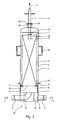
- FIG. 2 shows a practical embodiment of a filter device 30 with a composite housing 4', 4" and a cylindrical filter element 5, which is supported by an inner peripheral edge 18 of an inlet chamber 16 which rests clear of the walls of housing 4', 4" on three legs 19, wherein the upper side of inlet chamber 16 is formed by the lower end surface 6 of filter element 5, sealed by an O-ring 15.
- Extending from the underside of the cylinder surface of holder part 4' is an inlet conduit 8 debouching into inlet chamber 16, in the cylinder surface there is arranged an outlet opening 13 to which an outlet conduit 9 is connected.
- Extending through cover part 4" is an outlet conduit 21 for permeate 3 which supports with a bumper 22 on the upper surface 7 of filter element 5, protrudes in a central permeate tube in filter element 5 in liquid-tight manner with two O-rings 23, and is sealed with a third O-ring 24 between flanges 26', 26" on the upper side of cover part 4".
- the permeate conduit 21 is first pulled out of filter element 5 and housing 4", whereafter flanges 17', 17" are uncoupled and cover part 4" can be lifted upward by the handles 25 arranged for this purpose.
- Filter element 5 is subsequently lifted off the edge 18 of inlet chamber 6, which can if desired also be taken out of holder part 4' for maintenance or cleaning.
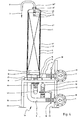
- Fig. 3 shows a filter device 40 which differs from filter device 30 shown in fig. 2 in that inlet conduit 8 and outlet conduit 9 both extend downward from the bottom 27 of holder part 4' of the housing and debouch in respective collecting conduits 28, 29, to which a plurality of filter devices 40 can be connected in parallel.
- Fig. 4 shows a filter device 50 with a vertically placed housing 4', 4", wherein inlet conduit 8 extends from the underside 27 of housing 4', 4" and an outlet conduit 9 extends from the outer surface of housing 4', 4".
- the underside of housing 4', 4" is formed by a support plate 27, which rests with two bent edges 31 on a yoke 32 with foot supports 33, to which the collecting conduits 28, 29 are also attached.
- the figure further shows valves 38, 39 in respectively the inlet conduit 8 and outlet conduit 9, and a secondary inlet conduit 41 and a secondary outlet conduit 43, which are connected via respective valves 42, 44 to respectively the inlet conduit 8 and outlet conduit 9 for guiding a flushing liquid through filter device 50.
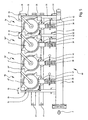
- Fig. 5 shows a modular assembly of a filter installation 60 with four filter devices connected in parallel, wherein a first module (on the left in the figure) comprises three filter devices 50, 50', 50" on a collective support plate 27', and a second module (on the right in the figure) comprises one filter device 50 on a support plate 27.
- inventive concept extends to filter devices with a composite housing, wherein an outlet conduit for concentrate extends through a bottom surface, and an inlet conduit for liquid for filtering extends through the outer surface of the housing, and to filter devices wherein the outlet conduit for the permeate extends on the same side of the housing as the inlet conduit for liquid for filtering or the outlet conduit for concentrate.
Landscapes
- Chemical & Material Sciences (AREA)
- Chemical Kinetics & Catalysis (AREA)
- Filtration Of Liquid (AREA)
- Separation Using Semi-Permeable Membranes (AREA)
Claims (9)
- Filtervorrichtung (20, 30, 40, 50) zum Trennen einer zu filtrierenden Flüssigkeit (1) mit einer ersten Konzentration an Teilchen in eine filtrierte Flüssigkeit (2) mit einer zweiten, höheren Konzentration an Teilchen und ein Permeat (3), und diese Vorrichtung umfasst ein zylindrisches Gehäuse (4', 4") und ein zylindrisches Filterelement (5), das in Achsenrichtung in besagtem Gehäuse (4', 4") aufgenommen ist und das an einer ersten Endfläche (6) zum in Achsenrichtung Einlassen der zu filtrierenden Flüssigkeit (1) eingerichtet ist und an einer gegenüberliegenden zweiten Endfläche (7) zum in Achsenrichtung Auslassen der filtrierten Flüssigkeit (2) eingerichtet ist, und dieses Filterelement (5) ist weiter mit Auslassmitteln (21) für das Permeat (3) versehen, wobei das Gehäuse (4', 4") mit Einlassmitteln (8, 16) zum Einlassen der zu filtrierenden Flüssigkeit (1) und Auslassmitteln (9, 13) zum Auslassen der filtrierten Flüssigkeit (2) und des Permeats (3) versehen ist, wobei das Gehäuse (4', 4") eingerichtet ist, um die filtrierte Flüssigkeit (2) in einen Auslassraum (11) zwischen dem Filterelement (5) und dem Gehäuse (4', 4") in einer Richtung entgegengesetzt zur Richtung der zu filtrierenden Flüssigkeit (1) durch das Filterelement zu leiten, wobei
die Einlassmittel eine Einlasskammer (16), von der ein Wandteil zumindest teilweise von der ersten Endfläche (6) des Filterelements (5) gebildet wird, sowie eine in die Kammer (16) einmündende Einlassleitung (8) umfassen,
die zweite Endfläche (7) in offener Verbindung mit einem sich zumindest zwischen der Außenfläche des Filterelements (5) und dem Gehäuse (4', 4") erstreckenden Auslassraum (11) steht, und
die Auslassmittel eine in Bezug auf die zweite Endfläche (7) distal angebrachte Auslassöffnung (13) in dem Auslassraum (11) umfassen, dadurch gekennzeichnet, dass die Einlasskammer (16) frei von der Zylinderfläche und den Endflächen des Gehäuses (4', 4") angebracht ist. - Filtervorrichtung (20, 30, 40, 50) nach Anspruch 1, dadurch gekennzeichnet, dass die Einlasskammer eine zylindrische Kammer (16) umfasst.
- Filtervorrichtung (20, 30, 40, 50) nach einem der Ansprüche 1-2, dadurch gekennzeichnet, dass das Gehäuse (4', 4") aus einem Behälterteil (4'), an welches das Filterelement (5) trennbar gekoppelt ist und von welchem sich eine Einlassleitung (8) für zu filtrierende Flüssigkeit (1) und eine Auslassleitung (9) für filtrierte Flüssigkeit (2) erstrecken, und einem Deckelteil (4"), welches trennbar an das Behälterteil gekoppelt werden kann, zusammengesetzt ist.
- Filtervorrichtung (30, 40) nach Anspruch 3, dadurch gekennzeichnet, dass das Deckelteil (4") mit Griffen (25) versehen ist.
- Filtervorrichtung (30) nach einem der obigen Ansprüche, dadurch gekennzeichnet, dass das Gehäuse (4', 4") vertikal gestellt werden kann und sich im Betriebszustand eine Einlassleitung (8) für zu filtrierende Flüssigkeit (1) und eine Auslassleitung (9) für filtrierte Flüssigkeit (2) von der Außenfläche des Gehäuses (4', 4") aus auf einer Höhe nahe der Unterseite (27) erstrecken.
- Filtervorrichtung (20, 30, 40) nach einem der obigen Ansprüche, dadurch gekennzeichnet, dass die Auslassmittel eine sich von der Auslassöffnung (13) aus erstreckende Auslassleitung (9) umfassen, wobei sich besagte Auslassleitung (9) und die Einlassleitung (8) durch dieselbe Endfläche des Gehäuses (4', 4") erstrecken.
- Filtervorrichtung (20, 40) nach Anspruch 6, dadurch gekennzeichnet, dass das Gehäuse (4', 4") vertikal gestellt werden kann und sich im Betriebszustand eine Einlassleitung (8) für zu filtrierende Flüssigkeit (1) und eine Auslassleitung (9) für filtrierte Flüssigkeit (2) von der Unterseite (27) des Gehäuses (4', 4") aus erstrecken.
- Filtervorrichtung (50) nach einem der Ansprüche 1-5, dadurch gekennzeichnet, dass das Gehäuse (4', 4") vertikal gestellt werden kann, sich im Betriebszustand eine Einlassleitung (8) für zu filtrierende Flüssigkeit (1) von der Unterseite (27) des Gehäuses (4', 4") aus erstreckt und sich eine Auslassleitung (9) für filtrierte Flüssigkeit (2) von der Außenfläche des Gehäuses (4', 4") aus erstreckt.
- Filtervorrichtung (50) nach einem der obigen Ansprüche, wobei das Gehäuse (4', 4") vertikal gestellt werden kann, dadurch gekennzeichnet, dass die Unterseite (27', 27") des Gehäuses (4', 4") aus einer Trägerplatte besteht, welche sich bis zu einer Position außerhalb der Peripherie des Gehäuses (4', 4") erstreckt und welche die Unterseite des Gehäuses (4', 4") von zumindest einer zweiten Filtervorrichtung (50') nach einem der obigen Ansprüche bildet.
Priority Applications (1)
| Application Number | Priority Date | Filing Date | Title |
|---|---|---|---|
| PL04077775T PL1524026T3 (pl) | 2003-10-16 | 2004-10-06 | Urządzenie filtrujące do rozdzielania cieczy zawierającej cząsteczki na koncentrat i przesącz |
Applications Claiming Priority (2)
| Application Number | Priority Date | Filing Date | Title |
|---|---|---|---|
| NL1024557A NL1024557C2 (nl) | 2003-10-16 | 2003-10-16 | Filterinrichting voor het scheiden van een deeltjeshoudende vloeistof in een concentraat en een permeaat. |
| NL1024557 | 2003-10-16 |
Publications (2)
| Publication Number | Publication Date |
|---|---|
| EP1524026A1 EP1524026A1 (de) | 2005-04-20 |
| EP1524026B1 true EP1524026B1 (de) | 2008-01-23 |
Family
ID=34374410
Family Applications (1)
| Application Number | Title | Priority Date | Filing Date |
|---|---|---|---|
| EP04077775A Expired - Lifetime EP1524026B1 (de) | 2003-10-16 | 2004-10-06 | Filtervorrichtung zur Trennung einer teilchenhaltigen Flüssigkeit in ein Konzentrat und ein Permeat |
Country Status (6)
| Country | Link |
|---|---|
| US (1) | US20050082216A1 (de) |
| EP (1) | EP1524026B1 (de) |
| AT (1) | ATE384572T1 (de) |
| DE (1) | DE602004011441T2 (de) |
| NL (1) | NL1024557C2 (de) |
| PL (1) | PL1524026T3 (de) |
Families Citing this family (3)
| Publication number | Priority date | Publication date | Assignee | Title |
|---|---|---|---|---|
| US8261919B2 (en) * | 2010-08-25 | 2012-09-11 | Dow Global Technologies Llc | Fluid filter module including handle |
| US8173018B2 (en) | 2010-08-25 | 2012-05-08 | Dow Global Technologies Llc | Fluid filter module including sealed boss |
| CN114307645B (zh) * | 2021-12-10 | 2023-06-20 | 深圳汇芯生物医疗科技有限公司 | 液体回收装置 |
Family Cites Families (8)
| Publication number | Priority date | Publication date | Assignee | Title |
|---|---|---|---|---|
| US4767531A (en) * | 1986-09-02 | 1988-08-30 | Eastman Kodak Company | Retractor for permeator or filter module |
| US4744900A (en) * | 1987-04-20 | 1988-05-17 | Bratt Russell I | Reverse osmosis membrane container |
| NL8702149A (nl) * | 1987-09-09 | 1989-04-03 | Tno | Membraanmodule voor hyperfiltratie of ultrafiltratie van vervuilende vloeistofstromen. |
| DE3928124A1 (de) * | 1989-08-25 | 1991-02-28 | Guenter Lauer | Verfahren zur aufbereitung einer fluessigkeit sowie filterelement, insbesondere zur durchfuehrung des verfahrens |
| US5221473A (en) * | 1989-10-13 | 1993-06-22 | Burrows Bruce D | Filter cartridge assembly for a reverse osmosis purification system |
| US5128037A (en) * | 1990-12-27 | 1992-07-07 | Millipore Corporation | Spiral wound filtration membrane cartridge |
| US5891334A (en) * | 1997-06-19 | 1999-04-06 | Plymouth Products, Inc. | Filter cartridge retaining assembly |
| US6224767B1 (en) * | 1998-03-20 | 2001-05-01 | Toray Industries Inc. | Fluid separation element assembly |
-
2003
- 2003-10-16 NL NL1024557A patent/NL1024557C2/nl not_active IP Right Cessation
-
2004
- 2004-10-06 PL PL04077775T patent/PL1524026T3/pl unknown
- 2004-10-06 AT AT04077775T patent/ATE384572T1/de not_active IP Right Cessation
- 2004-10-06 DE DE602004011441T patent/DE602004011441T2/de not_active Expired - Lifetime
- 2004-10-06 EP EP04077775A patent/EP1524026B1/de not_active Expired - Lifetime
- 2004-10-12 US US10/961,193 patent/US20050082216A1/en not_active Abandoned
Also Published As
| Publication number | Publication date |
|---|---|
| EP1524026A1 (de) | 2005-04-20 |
| DE602004011441D1 (de) | 2008-03-13 |
| ATE384572T1 (de) | 2008-02-15 |
| PL1524026T3 (pl) | 2008-06-30 |
| DE602004011441T2 (de) | 2009-02-19 |
| NL1024557C2 (nl) | 2005-04-20 |
| US20050082216A1 (en) | 2005-04-21 |
Similar Documents
| Publication | Publication Date | Title |
|---|---|---|
| US10898836B2 (en) | Filter with exterior and interior media components and method of filtering | |
| EP2678092B1 (de) | Mehrstufiges filterelement | |
| CN101437592B (zh) | 过滤器组件 | |
| US6830683B2 (en) | Filter cartridge assembly with brine seal and retaining ring | |
| EP0858825B1 (de) | Kraftstofffilter mit Entlüftungssystem | |
| US5891334A (en) | Filter cartridge retaining assembly | |
| US12576348B2 (en) | Advanced fuel filtration system with interlocking cartridge seal design | |
| US20240082761A1 (en) | Retrofitting and use of rectangular filters, assembly and method for filtration | |
| WO2003002229A1 (en) | Filtration module including unitary filter cartridge-bowl construction | |
| EP1524026B1 (de) | Filtervorrichtung zur Trennung einer teilchenhaltigen Flüssigkeit in ein Konzentrat und ein Permeat | |
| US9422182B2 (en) | Water purifier system and a filter element for such system | |
| EP0191721A2 (de) | Zellenfilter | |
| US20240034642A1 (en) | Water filter system for domestic and commercial use | |
| WO2003033101A1 (en) | Modular filter | |
| US10016706B2 (en) | Disk type filtering apparatus | |
| RU180580U1 (ru) | Фильтр-сгуститель | |
| EP1222011B1 (de) | Filterelementanordnung | |
| US11939242B1 (en) | Housing for water filter cartridges | |
| WO2019040867A1 (en) | CORNER-SHAPED FILTERS, ASSEMBLY AND METHOD OF FILTRATION AND COALESCENCE | |
| US20030173311A1 (en) | Servo sandwich filter assembly | |
| CN210159277U (zh) | 一种滤水装置及滤芯固定装置 | |
| KR102463982B1 (ko) | 필터지 교체 기능을 갖는 물시료 필터 장치 | |
| CN216677337U (zh) | 干洗机过滤组件 | |
| AU2021101403B4 (en) | A filter system for a pool |
Legal Events
| Date | Code | Title | Description |
|---|---|---|---|
| PUAI | Public reference made under article 153(3) epc to a published international application that has entered the european phase |
Free format text: ORIGINAL CODE: 0009012 |
|
| AK | Designated contracting states |
Kind code of ref document: A1 Designated state(s): AT BE BG CH CY CZ DE DK EE ES FI FR GB GR HU IE IT LI LU MC NL PL PT RO SE SI SK TR |
|
| AX | Request for extension of the european patent |
Extension state: AL HR LT LV MK |
|
| 17P | Request for examination filed |
Effective date: 20050929 |
|
| AKX | Designation fees paid |
Designated state(s): AT BE BG CH CY CZ DE DK EE ES FI FR GB GR HU IE IT LI LU MC NL PL PT RO SE SI SK TR |
|
| 17Q | First examination report despatched |
Effective date: 20060330 |
|
| GRAP | Despatch of communication of intention to grant a patent |
Free format text: ORIGINAL CODE: EPIDOSNIGR1 |
|
| GRAS | Grant fee paid |
Free format text: ORIGINAL CODE: EPIDOSNIGR3 |
|
| GRAA | (expected) grant |
Free format text: ORIGINAL CODE: 0009210 |
|
| AK | Designated contracting states |
Kind code of ref document: B1 Designated state(s): AT BE BG CH CY CZ DE DK EE ES FI FR GB GR HU IE IT LI LU MC NL PL PT RO SE SI SK TR |
|
| REG | Reference to a national code |
Ref country code: GB Ref legal event code: FG4D |
|
| REG | Reference to a national code |
Ref country code: CH Ref legal event code: EP |
|
| REG | Reference to a national code |
Ref country code: IE Ref legal event code: FG4D |
|
| REF | Corresponds to: |
Ref document number: 602004011441 Country of ref document: DE Date of ref document: 20080313 Kind code of ref document: P |
|
| REG | Reference to a national code |
Ref country code: PL Ref legal event code: T3 |
|
| NLV1 | Nl: lapsed or annulled due to failure to fulfill the requirements of art. 29p and 29m of the patents act | ||
| PG25 | Lapsed in a contracting state [announced via postgrant information from national office to epo] |
Ref country code: FI Free format text: LAPSE BECAUSE OF FAILURE TO SUBMIT A TRANSLATION OF THE DESCRIPTION OR TO PAY THE FEE WITHIN THE PRESCRIBED TIME-LIMIT Effective date: 20080123 Ref country code: LI Free format text: LAPSE BECAUSE OF FAILURE TO SUBMIT A TRANSLATION OF THE DESCRIPTION OR TO PAY THE FEE WITHIN THE PRESCRIBED TIME-LIMIT Effective date: 20080123 Ref country code: ES Free format text: LAPSE BECAUSE OF FAILURE TO SUBMIT A TRANSLATION OF THE DESCRIPTION OR TO PAY THE FEE WITHIN THE PRESCRIBED TIME-LIMIT Effective date: 20080504 Ref country code: CH Free format text: LAPSE BECAUSE OF FAILURE TO SUBMIT A TRANSLATION OF THE DESCRIPTION OR TO PAY THE FEE WITHIN THE PRESCRIBED TIME-LIMIT Effective date: 20080123 |
|
| REG | Reference to a national code |
Ref country code: CH Ref legal event code: PL |
|
| PG25 | Lapsed in a contracting state [announced via postgrant information from national office to epo] |
Ref country code: AT Free format text: LAPSE BECAUSE OF FAILURE TO SUBMIT A TRANSLATION OF THE DESCRIPTION OR TO PAY THE FEE WITHIN THE PRESCRIBED TIME-LIMIT Effective date: 20080123 Ref country code: BG Free format text: LAPSE BECAUSE OF FAILURE TO SUBMIT A TRANSLATION OF THE DESCRIPTION OR TO PAY THE FEE WITHIN THE PRESCRIBED TIME-LIMIT Effective date: 20080423 |
|
| ET | Fr: translation filed | ||
| PG25 | Lapsed in a contracting state [announced via postgrant information from national office to epo] |
Ref country code: SI Free format text: LAPSE BECAUSE OF FAILURE TO SUBMIT A TRANSLATION OF THE DESCRIPTION OR TO PAY THE FEE WITHIN THE PRESCRIBED TIME-LIMIT Effective date: 20080123 Ref country code: BE Free format text: LAPSE BECAUSE OF FAILURE TO SUBMIT A TRANSLATION OF THE DESCRIPTION OR TO PAY THE FEE WITHIN THE PRESCRIBED TIME-LIMIT Effective date: 20080123 Ref country code: PT Free format text: LAPSE BECAUSE OF FAILURE TO SUBMIT A TRANSLATION OF THE DESCRIPTION OR TO PAY THE FEE WITHIN THE PRESCRIBED TIME-LIMIT Effective date: 20080623 |
|
| PG25 | Lapsed in a contracting state [announced via postgrant information from national office to epo] |
Ref country code: CZ Free format text: LAPSE BECAUSE OF FAILURE TO SUBMIT A TRANSLATION OF THE DESCRIPTION OR TO PAY THE FEE WITHIN THE PRESCRIBED TIME-LIMIT Effective date: 20080123 Ref country code: DK Free format text: LAPSE BECAUSE OF FAILURE TO SUBMIT A TRANSLATION OF THE DESCRIPTION OR TO PAY THE FEE WITHIN THE PRESCRIBED TIME-LIMIT Effective date: 20080123 Ref country code: SE Free format text: LAPSE BECAUSE OF FAILURE TO SUBMIT A TRANSLATION OF THE DESCRIPTION OR TO PAY THE FEE WITHIN THE PRESCRIBED TIME-LIMIT Effective date: 20080423 Ref country code: SK Free format text: LAPSE BECAUSE OF FAILURE TO SUBMIT A TRANSLATION OF THE DESCRIPTION OR TO PAY THE FEE WITHIN THE PRESCRIBED TIME-LIMIT Effective date: 20080123 Ref country code: NL Free format text: LAPSE BECAUSE OF FAILURE TO SUBMIT A TRANSLATION OF THE DESCRIPTION OR TO PAY THE FEE WITHIN THE PRESCRIBED TIME-LIMIT Effective date: 20080123 |
|
| PG25 | Lapsed in a contracting state [announced via postgrant information from national office to epo] |
Ref country code: RO Free format text: LAPSE BECAUSE OF FAILURE TO SUBMIT A TRANSLATION OF THE DESCRIPTION OR TO PAY THE FEE WITHIN THE PRESCRIBED TIME-LIMIT Effective date: 20080123 |
|
| PLBE | No opposition filed within time limit |
Free format text: ORIGINAL CODE: 0009261 |
|
| STAA | Information on the status of an ep patent application or granted ep patent |
Free format text: STATUS: NO OPPOSITION FILED WITHIN TIME LIMIT |
|
| 26N | No opposition filed |
Effective date: 20081024 |
|
| PG25 | Lapsed in a contracting state [announced via postgrant information from national office to epo] |
Ref country code: EE Free format text: LAPSE BECAUSE OF FAILURE TO SUBMIT A TRANSLATION OF THE DESCRIPTION OR TO PAY THE FEE WITHIN THE PRESCRIBED TIME-LIMIT Effective date: 20080123 |
|
| PG25 | Lapsed in a contracting state [announced via postgrant information from national office to epo] |
Ref country code: MC Free format text: LAPSE BECAUSE OF NON-PAYMENT OF DUE FEES Effective date: 20081031 |
|
| PG25 | Lapsed in a contracting state [announced via postgrant information from national office to epo] |
Ref country code: CY Free format text: LAPSE BECAUSE OF FAILURE TO SUBMIT A TRANSLATION OF THE DESCRIPTION OR TO PAY THE FEE WITHIN THE PRESCRIBED TIME-LIMIT Effective date: 20080123 |
|
| PG25 | Lapsed in a contracting state [announced via postgrant information from national office to epo] |
Ref country code: IT Free format text: LAPSE BECAUSE OF FAILURE TO SUBMIT A TRANSLATION OF THE DESCRIPTION OR TO PAY THE FEE WITHIN THE PRESCRIBED TIME-LIMIT Effective date: 20080123 |
|
| PG25 | Lapsed in a contracting state [announced via postgrant information from national office to epo] |
Ref country code: IE Free format text: LAPSE BECAUSE OF NON-PAYMENT OF DUE FEES Effective date: 20081006 |
|
| PG25 | Lapsed in a contracting state [announced via postgrant information from national office to epo] |
Ref country code: LU Free format text: LAPSE BECAUSE OF NON-PAYMENT OF DUE FEES Effective date: 20081006 Ref country code: HU Free format text: LAPSE BECAUSE OF FAILURE TO SUBMIT A TRANSLATION OF THE DESCRIPTION OR TO PAY THE FEE WITHIN THE PRESCRIBED TIME-LIMIT Effective date: 20080724 |
|
| PG25 | Lapsed in a contracting state [announced via postgrant information from national office to epo] |
Ref country code: TR Free format text: LAPSE BECAUSE OF FAILURE TO SUBMIT A TRANSLATION OF THE DESCRIPTION OR TO PAY THE FEE WITHIN THE PRESCRIBED TIME-LIMIT Effective date: 20080123 |
|
| PG25 | Lapsed in a contracting state [announced via postgrant information from national office to epo] |
Ref country code: GR Free format text: LAPSE BECAUSE OF FAILURE TO SUBMIT A TRANSLATION OF THE DESCRIPTION OR TO PAY THE FEE WITHIN THE PRESCRIBED TIME-LIMIT Effective date: 20080424 |
|
| REG | Reference to a national code |
Ref country code: FR Ref legal event code: PLFP Year of fee payment: 12 |
|
| REG | Reference to a national code |
Ref country code: FR Ref legal event code: PLFP Year of fee payment: 13 |
|
| PGFP | Annual fee paid to national office [announced via postgrant information from national office to epo] |
Ref country code: PL Payment date: 20160930 Year of fee payment: 13 |
|
| PGFP | Annual fee paid to national office [announced via postgrant information from national office to epo] |
Ref country code: FR Payment date: 20160928 Year of fee payment: 13 |
|
| REG | Reference to a national code |
Ref country code: FR Ref legal event code: ST Effective date: 20180629 |
|
| PG25 | Lapsed in a contracting state [announced via postgrant information from national office to epo] |
Ref country code: FR Free format text: LAPSE BECAUSE OF NON-PAYMENT OF DUE FEES Effective date: 20171031 |
|
| PGFP | Annual fee paid to national office [announced via postgrant information from national office to epo] |
Ref country code: DE Payment date: 20181015 Year of fee payment: 15 |
|
| PG25 | Lapsed in a contracting state [announced via postgrant information from national office to epo] |
Ref country code: PL Free format text: LAPSE BECAUSE OF NON-PAYMENT OF DUE FEES Effective date: 20171006 |
|
| PGFP | Annual fee paid to national office [announced via postgrant information from national office to epo] |
Ref country code: GB Payment date: 20191022 Year of fee payment: 16 |
|
| REG | Reference to a national code |
Ref country code: DE Ref legal event code: R119 Ref document number: 602004011441 Country of ref document: DE |
|
| PG25 | Lapsed in a contracting state [announced via postgrant information from national office to epo] |
Ref country code: DE Free format text: LAPSE BECAUSE OF NON-PAYMENT OF DUE FEES Effective date: 20200501 |
|
| GBPC | Gb: european patent ceased through non-payment of renewal fee |
Effective date: 20201006 |
|
| PG25 | Lapsed in a contracting state [announced via postgrant information from national office to epo] |
Ref country code: GB Free format text: LAPSE BECAUSE OF NON-PAYMENT OF DUE FEES Effective date: 20201006 |