EP1523965A2 - Knochenverdichter mit radialer Beaufschlagung - Google Patents
Knochenverdichter mit radialer Beaufschlagung Download PDFInfo
- Publication number
- EP1523965A2 EP1523965A2 EP04255788A EP04255788A EP1523965A2 EP 1523965 A2 EP1523965 A2 EP 1523965A2 EP 04255788 A EP04255788 A EP 04255788A EP 04255788 A EP04255788 A EP 04255788A EP 1523965 A2 EP1523965 A2 EP 1523965A2
- Authority
- EP
- European Patent Office
- Prior art keywords
- component
- instrument
- bone
- longitudinal axis
- present
- Prior art date
- Legal status (The legal status is an assumption and is not a legal conclusion. Google has not performed a legal analysis and makes no representation as to the accuracy of the status listed.)
- Granted
Links
- 210000000988 bone and bone Anatomy 0.000 title claims abstract description 102
- 239000000463 material Substances 0.000 claims abstract description 55
- 230000033001 locomotion Effects 0.000 claims description 26
- 230000000452 restraining effect Effects 0.000 claims description 12
- 239000011800 void material Substances 0.000 claims description 4
- 239000002245 particle Substances 0.000 claims description 2
- 239000007943 implant Substances 0.000 description 40
- 230000007246 mechanism Effects 0.000 description 26
- 230000036961 partial effect Effects 0.000 description 19
- 238000001356 surgical procedure Methods 0.000 description 16
- 238000000034 method Methods 0.000 description 15
- 239000004568 cement Substances 0.000 description 12
- 210000000689 upper leg Anatomy 0.000 description 11
- 210000000845 cartilage Anatomy 0.000 description 10
- 230000013011 mating Effects 0.000 description 9
- 210000001519 tissue Anatomy 0.000 description 9
- 210000001503 joint Anatomy 0.000 description 8
- 230000008901 benefit Effects 0.000 description 7
- 238000006073 displacement reaction Methods 0.000 description 7
- 208000012659 Joint disease Diseases 0.000 description 6
- 239000012858 resilient material Substances 0.000 description 6
- 208000036487 Arthropathies Diseases 0.000 description 5
- 206010003246 arthritis Diseases 0.000 description 5
- 238000011882 arthroplasty Methods 0.000 description 5
- 230000001054 cortical effect Effects 0.000 description 5
- 210000001624 hip Anatomy 0.000 description 4
- 238000003780 insertion Methods 0.000 description 4
- 230000037431 insertion Effects 0.000 description 4
- 230000008569 process Effects 0.000 description 4
- 230000002441 reversible effect Effects 0.000 description 4
- 238000010079 rubber tapping Methods 0.000 description 4
- 206010061218 Inflammation Diseases 0.000 description 3
- 210000000588 acetabulum Anatomy 0.000 description 3
- 239000008280 blood Substances 0.000 description 3
- 210000004369 blood Anatomy 0.000 description 3
- 239000012530 fluid Substances 0.000 description 3
- 230000003116 impacting effect Effects 0.000 description 3
- 230000004054 inflammatory process Effects 0.000 description 3
- 208000014674 injury Diseases 0.000 description 3
- 210000003127 knee Anatomy 0.000 description 3
- 238000012856 packing Methods 0.000 description 3
- 210000004197 pelvis Anatomy 0.000 description 3
- 230000008733 trauma Effects 0.000 description 3
- 208000003076 Osteolysis Diseases 0.000 description 2
- 239000004698 Polyethylene Substances 0.000 description 2
- WAIPAZQMEIHHTJ-UHFFFAOYSA-N [Cr].[Co] Chemical compound [Cr].[Co] WAIPAZQMEIHHTJ-UHFFFAOYSA-N 0.000 description 2
- 210000003423 ankle Anatomy 0.000 description 2
- 238000005056 compaction Methods 0.000 description 2
- 238000010276 construction Methods 0.000 description 2
- 238000005520 cutting process Methods 0.000 description 2
- 201000010099 disease Diseases 0.000 description 2
- 208000037265 diseases, disorders, signs and symptoms Diseases 0.000 description 2
- 238000005516 engineering process Methods 0.000 description 2
- 210000004394 hip joint Anatomy 0.000 description 2
- 238000005461 lubrication Methods 0.000 description 2
- 208000029791 lytic metastatic bone lesion Diseases 0.000 description 2
- 238000004519 manufacturing process Methods 0.000 description 2
- 229910052751 metal Inorganic materials 0.000 description 2
- 239000002184 metal Substances 0.000 description 2
- -1 polyethylene Polymers 0.000 description 2
- 229920000573 polyethylene Polymers 0.000 description 2
- 229920000642 polymer Polymers 0.000 description 2
- 230000002829 reductive effect Effects 0.000 description 2
- 210000004872 soft tissue Anatomy 0.000 description 2
- 229910000684 Cobalt-chrome Inorganic materials 0.000 description 1
- 206010031264 Osteonecrosis Diseases 0.000 description 1
- 201000001263 Psoriatic Arthritis Diseases 0.000 description 1
- 208000036824 Psoriatic arthropathy Diseases 0.000 description 1
- 206010039203 Road traffic accident Diseases 0.000 description 1
- 229910001069 Ti alloy Inorganic materials 0.000 description 1
- RTAQQCXQSZGOHL-UHFFFAOYSA-N Titanium Chemical compound [Ti] RTAQQCXQSZGOHL-UHFFFAOYSA-N 0.000 description 1
- 230000017531 blood circulation Effects 0.000 description 1
- 230000036770 blood supply Effects 0.000 description 1
- 239000000316 bone substitute Substances 0.000 description 1
- 239000000919 ceramic Substances 0.000 description 1
- 239000010952 cobalt-chrome Substances 0.000 description 1
- 239000002131 composite material Substances 0.000 description 1
- 230000001010 compromised effect Effects 0.000 description 1
- 210000002808 connective tissue Anatomy 0.000 description 1
- 210000001513 elbow Anatomy 0.000 description 1
- 238000000605 extraction Methods 0.000 description 1
- 210000002082 fibula Anatomy 0.000 description 1
- 210000002758 humerus Anatomy 0.000 description 1
- 230000028993 immune response Effects 0.000 description 1
- 238000009434 installation Methods 0.000 description 1
- 210000003041 ligament Anatomy 0.000 description 1
- 230000000670 limiting effect Effects 0.000 description 1
- 206010025135 lupus erythematosus Diseases 0.000 description 1
- 150000002739 metals Chemical class 0.000 description 1
- 201000008482 osteoarthritis Diseases 0.000 description 1
- 230000009467 reduction Effects 0.000 description 1
- 238000002271 resection Methods 0.000 description 1
- 206010039073 rheumatoid arthritis Diseases 0.000 description 1
- 210000002832 shoulder Anatomy 0.000 description 1
- 229910001220 stainless steel Inorganic materials 0.000 description 1
- 239000010935 stainless steel Substances 0.000 description 1
- 229910001256 stainless steel alloy Inorganic materials 0.000 description 1
- 230000008961 swelling Effects 0.000 description 1
- 210000002435 tendon Anatomy 0.000 description 1
- 210000001694 thigh bone Anatomy 0.000 description 1
- 210000002303 tibia Anatomy 0.000 description 1
- 239000010936 titanium Substances 0.000 description 1
- 229910052719 titanium Inorganic materials 0.000 description 1
- 238000011541 total hip replacement Methods 0.000 description 1
- 230000000472 traumatic effect Effects 0.000 description 1
- 210000000623 ulna Anatomy 0.000 description 1
- 210000000707 wrist Anatomy 0.000 description 1
Images


Classifications
-
- A—HUMAN NECESSITIES
- A61—MEDICAL OR VETERINARY SCIENCE; HYGIENE
- A61B—DIAGNOSIS; SURGERY; IDENTIFICATION
- A61B17/00—Surgical instruments, devices or methods
- A61B17/56—Surgical instruments or methods for treatment of bones or joints; Devices specially adapted therefor
- A61B17/58—Surgical instruments or methods for treatment of bones or joints; Devices specially adapted therefor for osteosynthesis, e.g. bone plates, screws or setting implements
- A61B17/88—Osteosynthesis instruments; Methods or means for implanting or extracting internal or external fixation devices
- A61B17/885—Tools for expanding or compacting bones or discs or cavities therein
- A61B17/8852—Tools for expanding or compacting bones or discs or cavities therein capable of being assembled or enlarged, or changing shape, inside the bone or disc
- A61B17/8858—Tools for expanding or compacting bones or discs or cavities therein capable of being assembled or enlarged, or changing shape, inside the bone or disc laterally or radially expansible
-
- A—HUMAN NECESSITIES
- A61—MEDICAL OR VETERINARY SCIENCE; HYGIENE
- A61F—FILTERS IMPLANTABLE INTO BLOOD VESSELS; PROSTHESES; DEVICES PROVIDING PATENCY TO, OR PREVENTING COLLAPSING OF, TUBULAR STRUCTURES OF THE BODY, e.g. STENTS; ORTHOPAEDIC, NURSING OR CONTRACEPTIVE DEVICES; FOMENTATION; TREATMENT OR PROTECTION OF EYES OR EARS; BANDAGES, DRESSINGS OR ABSORBENT PADS; FIRST-AID KITS
- A61F2/00—Filters implantable into blood vessels; Prostheses, i.e. artificial substitutes or replacements for parts of the body; Appliances for connecting them with the body; Devices providing patency to, or preventing collapsing of, tubular structures of the body, e.g. stents
- A61F2/02—Prostheses implantable into the body
- A61F2/30—Joints
- A61F2/46—Special tools for implanting artificial joints
- A61F2/4601—Special tools for implanting artificial joints for introducing bone substitute, for implanting bone graft implants or for compacting them in the bone cavity
-
- A—HUMAN NECESSITIES
- A61—MEDICAL OR VETERINARY SCIENCE; HYGIENE
- A61B—DIAGNOSIS; SURGERY; IDENTIFICATION
- A61B17/00—Surgical instruments, devices or methods
- A61B2017/0046—Surgical instruments, devices or methods with a releasable handle; with handle and operating part separable
-
- A—HUMAN NECESSITIES
- A61—MEDICAL OR VETERINARY SCIENCE; HYGIENE
- A61F—FILTERS IMPLANTABLE INTO BLOOD VESSELS; PROSTHESES; DEVICES PROVIDING PATENCY TO, OR PREVENTING COLLAPSING OF, TUBULAR STRUCTURES OF THE BODY, e.g. STENTS; ORTHOPAEDIC, NURSING OR CONTRACEPTIVE DEVICES; FOMENTATION; TREATMENT OR PROTECTION OF EYES OR EARS; BANDAGES, DRESSINGS OR ABSORBENT PADS; FIRST-AID KITS
- A61F2/00—Filters implantable into blood vessels; Prostheses, i.e. artificial substitutes or replacements for parts of the body; Appliances for connecting them with the body; Devices providing patency to, or preventing collapsing of, tubular structures of the body, e.g. stents
- A61F2/02—Prostheses implantable into the body
- A61F2/30—Joints
- A61F2/32—Joints for the hip
- A61F2/36—Femoral heads ; Femoral endoprostheses
-
- A—HUMAN NECESSITIES
- A61—MEDICAL OR VETERINARY SCIENCE; HYGIENE
- A61F—FILTERS IMPLANTABLE INTO BLOOD VESSELS; PROSTHESES; DEVICES PROVIDING PATENCY TO, OR PREVENTING COLLAPSING OF, TUBULAR STRUCTURES OF THE BODY, e.g. STENTS; ORTHOPAEDIC, NURSING OR CONTRACEPTIVE DEVICES; FOMENTATION; TREATMENT OR PROTECTION OF EYES OR EARS; BANDAGES, DRESSINGS OR ABSORBENT PADS; FIRST-AID KITS
- A61F2/00—Filters implantable into blood vessels; Prostheses, i.e. artificial substitutes or replacements for parts of the body; Appliances for connecting them with the body; Devices providing patency to, or preventing collapsing of, tubular structures of the body, e.g. stents
- A61F2/02—Prostheses implantable into the body
- A61F2/30—Joints
- A61F2/46—Special tools for implanting artificial joints
- A61F2/4603—Special tools for implanting artificial joints for insertion or extraction of endoprosthetic joints or of accessories thereof
Definitions
- the present invention relates generally to the field of orthopaedics, and more particularly, to an instrument for use in arthroplasty.
- a joint within the human body forms a juncture between two or more bones or other skeletal parts.
- the ankle, hip, knee, shoulder, elbow and wrist are just a few examples of the multitude of joints found within the body.
- many of the joints permit relative motion between the bones.
- the motion of sliding, gliding, hinge or ball and socket movements may be had by a joint.
- the ankle permits a hinge movement
- the knee allows for a combination of gliding and hinge movements
- the shoulder and hip permit movement through a ball and socket arrangement.
- the joints in the body are stressed or can be damaged in a variety of ways. For example, the gradual wear and tear is imposed on the joints through the continuous use of a joint over the years.
- the joints that permit motion have cartilage positioned between the bones providing lubrication to the motion and also absorbing some of the forces direct to the joint. Over time, the normal use of a joint may wear down the cartilage and bring the moving bones in a direct contact with each other.
- a trauma to a joint such as the delivery of a large force, from an accident, for example, an automobile accident, may cause considerable damage to the bones, the cartilage or to other connective tissue such as tendons or ligaments.
- Arthropathy a term referring to a disease of the joint, is another way in which a joint may become damaged.
- arthritis which is generally referred to a disease or inflammation of a joint that results in pain, swelling, stiffness, instability, and often deformity.
- osteoarthritis are the most common and resulting from the wear and tear of a cartilage within a joint.
- Another type of arthritis is osteonecrosis, which is caused by the death of a part of the bone due to loss of blood supply.
- Other types of arthritis are caused by trauma to the joint while others, such as rheumatoid arthritis, Lupus, and psoriatic arthritis destroy cartilage and are associated with the inflammation of the joint lining.
- the hip joint is one of the joints that is commonly afflicted with arthropathy.
- the hip joint is a ball and socket joint that joins the femur or thigh bone with the pelvis.
- the pelvis has a semispherical socket called the acetabulum for receiving a ball socket head in the femur. Both the head of the femur and the acetabulum are coated with cartilage for allowing the femur to move easily within the pelvis.
- Other joints commonly afflicted with arthropathy include the spine, knee, shoulder, carpals, metacarpals, and phalanges of the hand. Arthroplasty as opposed to arthropathy commonly refers to the making of a artificial joint.
- the prosthetic implant is formed of a rigid material that becomes bonded with the bone and provides strength and rigidity to the joint and the cartilage substitute members chosen to provide lubrication to the joint and to absorb some of the compressive forces.
- Suitable material for the implant include metals, and composite materials such as titanium, cobalt chromium, stainless steel, ceramic and suitable materials for cartilage substitutes include polyethylene.
- a cement may also be used to secure the prosthetic implant to the host bone.
- a total hip replacement involves removing the ball shaped head of the femur and inserting a stem implant into the centre of the bone which is referred to as the medullary canal or marrow of the bone.
- the stem implant may be cemented into the medullary canal or may have a porous coated surface for allowing the bone to heal directly to the implant.
- the stem implant has a neck and a ball shaped head which are intended to perform the same functions as a healthy femur's neck and a ball shaped head.
- the polyethylene cup is inserted into the acetabulum and has a socket for receiving the head on the stem implant.
- Revision surgery may be required soon after the primary surgery or may not be needed for years. Revision surgery may be required for one of a number of reasons. For one, fixation of the joint may be compromised. A trauma of to the joint may result in the loosening or the loosening of the joint may have been caused by other factors, such as an insufficient bond between the implant and the host bone. The loosening of an implant can be quite painful and also can pose danger to the patient. For example, movement of the loose implant within the bone may fracture the bone itself.
- Revision surgery may be necessary for other reasons.
- particle debris from the cartilage substitute member or even from any of the other implants may cause osteolysis in the patient.
- osteolysis is the body's natural immune response to foreign objects which result in inflammation and pain in the joint.
- Another reason why revision surgery may be necessary, is due to death of part of the bone.
- a bone requires stress in order to remain strong and any bone that is not stressed will become weak and fragile. This result is often known as Wolfs Law.
- the insertion of an implant may stress shield portions of the bone whereby these portions no longer receive the stress that it requires in order to remain strong.
- Another reason to perform revision surgery is to take advantage of advancements in prosthetic design. Thus, for many reasons, revision surgery may be necessary or desirable for a patient.
- bone may be harvested from another portion of the patient to form an autograft which may be tamped in positioned in the bone cavity, for example the femur.
- substitute bone material may be used.
- Such bone material may be an allograft or human tissue available from a tissue bank or may be artificial tissue obtained from Pro OsteonTM available from Interpore, 181 Technology Drive, Irvine, California.
- a small portion of the autograft, the allograft, or the artificial bone material is bone is inserted into the femur and packed and the process is repeated until a portion of the femur has been filled.
- a tamping process may be performed which packs material into the medullary canal until the bone cavity is the proper size for the stem implant. This process may include the use of progressively large tamps until a tamp representing the size and shape of the implant's stem is used.
- blood pooled at the distal end of the stem may be extracted with suction applied in the tamp.
- the tamp is then removed just immediately prior to the insertion of the cement into the canal.
- a cement gun with a nozzle cut off to the length of the stem is use to inject cement into the narrow distal stem area.
- a second, larger nozzle may then be used to complete the filling of the proximal femur and to pressurize the cement.
- the stem is inserted and the pressure maintained until the cement has polymerized.
- This method is wrought with several problems.
- One of these problems is that in order to tamp the morselised bone into the cavity, the distal portion of the cavity must first be filled and a large quantity of graft material must be used. It may be traumatic for the patient as additional morselised bone must be harvested from the patient. Conversely, when bone substitute material issues, a larger and more expensive amount of material must be used. Further the packing of the entire canal may cause additional blood loss and blood flow as the blood is absorbed and moved toward the open portion of the cavity as the material continues to be packed by the tamps.
- the use of the tamps create a limit on the shape of the cavity created by the tamp as well as limiting the precision of the fit of the tamp to the prosthesis stem.
- the present invention is aimed at alleviating at least some of the aforementioned problems.
- the present invention provides for an instrument and related surgical technique that prepares the medullary canal by radial impaction of the morselised bone graft or allograft.
- the instrument provides for compacting bone graft material without compacting the bone distally at the same time.
- the present invention provides for a cavity receiving the distal stem without totally filling the canal distally to achieve the radial fill of the canal.
- the present invention provides for such a radial impaction of the bone graft by providing a two piece instrument with a first piece for insertion partially into the bone cavity and a second portion for moving radially outwardly toward the inner wall of the bone cavity to radially impact the morselised bone graft.
- an instrument for compacting bone material includes a first component defining a longitudinal axis of the first component and a second component.
- the second component is moveably associated with the first component.
- the second component is moveable at least partially in a radial direction outwardly from the longitudinal axis of the first component.
- an instrument for compacting bone material in a medullary canal of a long bone includes a first component defining a longitudinal axis of the first component.
- the first component has an outer periphery having a portion of the outer periphery which is tapered along the longitudinal axis.
- the portion of the outer periphery of the first component defines a restraining portion of the outer periphery.
- the first component also has a second component moveably associated with the first component.
- the second component defines a cooperating portion for cooperating with the restraining portion of the first component to provide restrained motion of the second component with respect to the first component.
- a method for preparing a cavity in a long bone includes the steps of cutting an incision in the patient, preparing a cavity in a long bone, providing an instrument for compacting bone material having a first component defining a longitudinal axis thereof and a second component moveable at least partially in a radial direction outwardly from the longitudinal axis of the first component, placing the instrument in the cavity, and compacting bone material in the cavity.
- the technical advantages of the present invention include the ability to provide radial impacting of bone graft material without filling the cavity distally and, thereby, with the use of a minimal amount of bone graft material.
- an instrument is provided with a first component which is moveable radially with respect to a second component to urge the bone material against the cortical wall of the long bone.
- the present invention provides for radial impacting of bone graft material without filling the cavity distally and with a minimal amount of bone graft material required.
- the technical advantage of the present invention further include the ability to provide for a greater radial impacting force.
- This greater impaction force may provide improved compaction of the bone graft material.
- an instrument is provided with a first component moveable radially with respect to a second component with the component which is moveable radially with respect to the longitudinal movement of the second component importing radial impaction force on the bone graft material.
- the present invention provides for greater radial impaction force and improved impaction of the bone graft material.
- Yet another technical advantage of the present invention includes the ability to provide a cavity for receiving an implant formed of bone graft material which provides a shape that matches the implant.
- the outer periphery of a first component which is moveable radially with respect to a second component may have a outer contour with a shape to conform with the prosthesis such that, as the instrument is used, the outer periphery of the instrument forms a cavity formed of the bone graft material which matches the shape of the implant.
- the present invention provides for a shape of a cavity that matches the shape of the implant.
- Such matching of the shape of the cavity of bone graft material to the implant provides for improved stability of the implant in the long bone.
- Yet another technical advantage of the present invention is the ability of the instrument of the present invention to replace a set of tamps with one instrument or tamp of the present invention.
- the ability to replace a set of tamps with a solitary instrument of the present invention will result in reduced inventory and reduced inventory cost and manufacturing cost for manufacturing a large quantity of sets of tamps.
- Prior art systems utilize a series of progressively larger tamps to form the cavity within the bone graft material.
- a solitary tamp which expands readily outward will replace this series of tamps.
- an instrument is provided with a first component moveable radially with respect to a second component to urge the bone material against the cortical wall of the bone.
- the radial motion of the first tamp provides for a tamp which can replace the set of progressively larger diameter tamps that would otherwise be required.
- the present invention provides for a solitary instrument to replace a set of multiple tamps.
- Another advantage of the present invention includes the ability to reduce the time of performing an arthroplasty.
- an instrument is provided with a first component moveable radially with respect to a second component to urge the bone material against the cortical wall of the bone.
- the instrument of the present invention is struck on the end of the instrument and the final form of the cavity for the implant is formed in one insertion of one instrument and one tamping of the instrument.
- a multitude of progressively larger tamps must be separately inserted and removed from the cavity and separately struck to compact the bone graft material.
- the present invention provides for a reduction in the time to perform an arthroplasty.
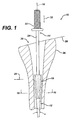
- FIG. 1 shows an instrument 10 for compacting bone material 12 is shown.
- the instrument 10 includes a first component 14 defining a longitudinal axis 16 of the first component 14.
- the instrument 10 also includes a second component 18 which is moveably associated with the first component 14.
- the second component 18 is moveable at least partially in a radial direction 20 outwardly from the longitudinal axis 16 of the first component 14.
- the first component 14 may, for example, include a body 22 and a stem 24 extending from the body 22.
- the second component 18 may, for example, be slidably mounted to the stem 24.
- the instrument 10 may be configured, for example, such that the first component 14 or the second component 18 is tapered along the longitudinal axis 16.
- both the first component 14 and the second component 18 may be tapered along the longitudinal axis.
- the instrument 10 may be used for example in conjunction with a long bone 26.
- the long bone 26 may be a femur, a tibia, a fibula, a humerus, an ulna, a radius, or any long bone in the skeletal system of a body.
- the instrument 10 is utilized to prepare a cavity for an implant.
- the instrument 10 is used to impact or tamp bone material 12.
- the long bone 26 is resected along resection line 28.
- Drills, reamers, and broaches and other instruments may be utilized to prepare medullary canal 30. While the instrument 10 may be utilized to assist in preparing the medullary canal 30 for a primary implant, it should be appreciated that the instrument 10 is particularly well suited for use with revision surgery.
- an existing prosthetic component placed in the canal 30 of the long bone is removed.
- additional bone and other tissue is inadvertently removed with the failed prosthetic stem.
- bone material may have grown or adhered to the surface of the prosthesis and additional bone maybe required to be remove around the stem to loosen the stem for its removal.
- the original or primary prosthesis was used with cement, the prosthesis as well as the cement adjoining the prosthesis will need to be removed to permit a revision surgery. In either case, with a revision surgery, whether the original stem was cemented or uncemented, additional bone and soft tissue are removed during the extraction of the failed prosthesis.
- Bone material 12 in the form of, for example, an autograft of the patient from another location of the patient, an allograft (human tissue from a tissue bank), or synthetic bone material such as Pro OsteonTM from Interpore, 181 Technology Drive, Irvine, California, maybe needed to prepare the medullary canal 30. As shown in FIG. 1 the bone material 12 must first be positioned in the medullary canal 30 and the instrument 10 inserted in the direction of arrow 32 into the medullary canal 30.
- the first component 14 may have any suitable shape capable of cooperating with the second component 18 and capable of clearance within the medullary canal 30. It should be appreciated that the first component 14 may have an uniform cross section along the longitudinal axis 16 and may have a simple cross section, for example, a circular cross section or a rectangular cross section. The portion of the first component 14 that passes into the medullary canal 30 preferably has a profile small enough for clearance with the canal 30.
- the proximal end 32 of the first component 14 may include a feature for assisting in moving the first component 14 in longitudinal direction 34.
- the first component 14 may include the body 22 which extends from the stem 24.
- the body 22 may be in the form of a handle and may be elongated along the longitudinal axis 16 and it may have, for example, a circular cross section.
- the body 22 may include knurls 36 on the periphery of the body 22 for assisting in gripping the instrument 10.
- a flange 38 may be positioned between the body 22 and the stem 24 for assisting and providing additional force on the instrument 10 in the direction of longitudinal direction 34.
- the second component 18 defines an outer periphery 40 thereof.
- the outer periphery 40 of the second component 18 preferably has a shape that replicates the outer periphery of the prosthesis.
- the outer periphery 40 may be cylindrical, have any polygon or other shape and may or may not be tapered.
- the outer periphery 40 may be defined by an included angle ⁇ thereof.
- the present invention may be practised with an instrument 10 having a solitary second component 18, in order that outer periphery 40 of second component 18 replicate the stem of a prosthesis, and in order that the outer periphery 40 of the second component 18 be moveable in the radial direction 20, the second component 18 must either be resilient or additional components must cooperate with the first component 14 and likewise be moveable in the radial direction 20.
- the second component 18 may in the form of a collet and include a series of slits to provide a resilient nature to the second component 18.
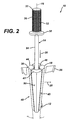
- the instrument 10 may further include a third component 42 moveably associated with the first component 14.
- the third component 42 is moveable at least partially in the radial direction 20 outwardly from the longitudinal axis 16 of the first component 14.
- the instrument 10 may further include a fourth component 44 moveably associated with the first component 14.
- the fourth component may be moveable at least partially in a radial direction 20 outwardly form the longitudinal axis 16 of the first component 14.
- the instrument 10 of the present invention may further include a fifth component 46.
- the fifth component 46 may be moveable at least partially in the radial direction 20 outwardly from the longitudinal axis 16 of the first component 14.
- Each of the second component 18, third component 42, fourth component 44, and fifth component 46 act to concert to form outer periphery 50 of the tamping portion 48 of the instrument 10.
- the tamping portion 48 of the instrument 10 is shown in greater detail. While the tapping portion 48 may be made of a single component, to provide for radial displacement in the radial direction 20, the tamping portion 48 as shown in FIG. 3 includes a plurality of components. Each of these plurality of components may move with respect to each other so that the tapping portion is moveable in the radial direction 20. Such multi piece construction provides for the opportunity to use strong and durable components.
- the tamping portion 48 may include two, three, four, or more components.
- the tapping portion 48 includes the four components.
- the components are second component 18, third component 42, fourth component 44, and fifth component 46. It should be appreciated that each of the components may be identical to each other or each component may be somewhat different in size and shape from the other components.
- the second component 18 includes the second component outer periphery 40.
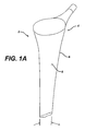
- the periphery 40 preferably corresponds to a portion of periphery 8 of the distal portion 6 of stem 4 (see FIG. 1A).
- the periphery 40 is preferably arcuate.
- the periphery 40 as shown in FIG. 3 may extend generally linearly and may be tapered inwardly along the longitudinal axis 16 from proximal end 52 to distal end 54 of the tamping portion 48.
- the second component 18 further includes a pair of spaced apart radial side walls 56.
- the side walls 56 extend gradually outward from the longitudinal axis 16 of the instrument 10.
- the side walls 56 form an included angle ⁇ there between.
- the angle ⁇ is approximately 90°.
- the tamping portion 48 may include a proximal internal lip 58 extending inwardly from proximal end 52 of the tapping portion 48.
- the lip 58 may be utilized to limit the motion of the second component 18 in the distal direction 60 along the longitudinal axis 16.
- the instrument of the present invention may be practised with a second component moveably associated with the first component, the second component may be interconnected or restrained within the first component so that the instrument may be easily inserted and removed from the cavity 30 of the long bone 26.
- the instrument 10 may include a restraining portion 60 that cooperates with a cooperating portion 62 of the second component 18.
- the restraining portion 60 and the cooperating portion 62 provide for restraining the motion of the second component 18 with respect to the first component 14.
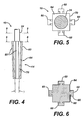
- the first component 14 may further include a base 64 extending distally from the stem 24 of the first component 14.
- the restraining portion 60 may have any size and shape capable of providing restrained motion of the second component 18 with respect to the first component 14.
- the restraining portion 60 may be in the form of a T shaped protrusion including a wide outer portion 66 and a narrow inner portion 68.
- the cooperating portion 62 of the second component 18 may be in the form of a T shaped slot extending axially along the longitudinal axis 16 of the second component 18.
- the T shaped protrusion 60 and the T shaped slot 62 may have uniform cross sections so that the second component 18 may freely move in the distal direction 69.
- the base 64 may include planar side walls 70 for cooperation with interior wall 72 of the second component 18.
- the first component 14 and the second component 18 may be made of any suitable durable material and may be made of a sterilizable material such as a metal or a polymer.
- the first component 14 and the second component 18 may be made of a stainless steel alloy, a cobalt chromium alloy, or a titanium alloy.
- the instrument 10 includes the first component 14 having a stem 24 and a base 64 extending from the stem 24.
- a series of axially extending protrusions 60 extend outwardly from the base 64.
- the base 64 is defined by a series as shown, of for example, four walls 70 defining the outer periphery of base 64.
- the walls 70 define an included angle ⁇ there between. The angle ⁇ provides outward movement of the second component 18 for packing of the bone material in the radial direction.
- the angle ⁇ may be chosen to provide for the proper radial force in comparison of the axial force and for providing the proper radial movement for a respective axial movement of the instrument 10.
- the included angle ⁇ may also be selected to provide for a corresponding relationship between radial displacement and axial displacement of the second component of the instrument 10 with respect to the first component of the instrument 10.
- the base 64 of the first component 14 of instrument 10 is shown greater detail.
- the base 64 may have a square cross section. It should be appreciated that the base 64 may have a rectangular cross section or have any shape. It should be appreciated that the instrument 10 should have one sliding surface or wall 70 corresponding to each of the sliding or second components. For example if the instrument includes three sliding components, the base would correspondingly be, for example triangular.
- the second component 18 may, and as embodied in the instrument 10 of the present invention, include a plurality of identical moveable components, namely, third component 42, fourth component 44, and fifth component 46.
- Each of the components 18, 42, 44, and 46 are identical to each other. It should be appreciated that conversely the components may have different sizes and shapes.
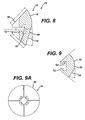
- the second component 18 is shown in greater detail in FIG. 7 and is illustrative of the size and shape of the third component 42 as well as the fourth and fifth components 44 and 46, respectively.
- the second component 18 includes a tapered arcuate periphery 40 and an opposed internal planar wall 72 for cooperation with one of the walls 70 of the base 64 of the first component 14 (see FIGS. 4-6).
- Second component 18 further includes the cooperating portion in the form of T-shaped slot 62 for cooperation with one of the T-shaped protrusions 60 of the first component 14.
- the second component 18 may further include a distal lip 74 opposed to the proximal lip 58.
- the second component 18 as shown in FIGS. 7, 8, 9 and 9A, may be tapered and may have a cross section that varies along the longitudinal axis 16 of the instrument 10.
- the outer periphery 40 of the first component 18 may be arcuate.
- the periphery 40 may include an arcuate first portion 76 and a linear portion 78.
- the arcuate portion 76 and the linear portions 78 cooperate to form, for example, a tamp with a rectangular cross section with rounded corners.
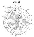
- Instrument 10 is shown in position in long bone 26.
- Instrument 10 includes the first component 14 as well as component 18.
- the instrument 10 is in position in the medullary canal 34 within the cortical bone 15 of the long bone 26.
- the bone material 12 is positioned between the cortical bone 15 and the periphery 50 of the tamping portion 48.
- the periphery 50 of the tamping portion 48 advances outwardly in the direction of arrow 23, thereby compressing or compacting the material 12.
- the tamping portion 48 may be rotated in the direction of arrow 17 about longitudinal axis 16 to further compact the material 12.
- the periphery 50 of the tamping portion 48 of the instrument 10 preferably replicates the shape of the corresponding part of the implant to be implanted.
- the implant 2 is shown for use with the instrument 10.
- the implant 2 includes a distal portion 6 which has a distal portion implant periphery 8 which preferably has the same size and shape as the periphery 50 of the tamping portion 48 of the instrument 10.
- the distal portion 6 may define an included angle ⁇ .
- the present invention may be practised with implants having an implant periphery of a variety of shapes including a generally rectangular square, round, triangular, or any suitable shape.
- Instrument 10A is shown. Instrument 10A is similar to instrument 10 except that base 64A of first component 14A has a generally rectangular cross section. Instrument 10A includes a second component 18A that is similar to the fourth component 44A and a third component 42A which is similar to the fifth component 46A. The components 18A, 42A, 44A and 46A define the periphery 50A of the tamping portion 48A. The periphery 50A of the instrument 10A is generally oval. The oval periphery 50A is of the instrument 10A is compatible for use with a stem (not shown) of a prosthesis which has an oval stem.
- Instrument 10B includes a first component 14B having a generally rectangular base 64B.
- Four additional components namely, first component 18B, second component 42B, third component 44B and fourth component 46B combine to form the conformed tamping portion 48B defining a tamping portion periphery 50B.
- the periphery 50B of the tamping portion 48B of the instrument 10B is generally circular and compatible with a prosthesis having a circular cross section.
- Instrument 10C is preferably for use with a prosthesis having a tapered oval cross section.
- the instrument 10C includes a first component 14C having a rectangular base 64C.
- Second component 18C, third component 42C, fourth component 44C, and fifth component 46C combine to form the tamping portion 48C defining the tamping portion periphery 50C.
- the tamping portion periphery 50C has a tapered oval shape corresponding to that of a implant having a tapered oval shape with which the instrument 10C would be utilized.
- Instrument 10D includes a first component 14D having a generally rectangular base 64D.
- Second component 18D, third component 42D, fourth component 44D, and fifth component 46D combine to form tamping portion 48D defining tamping portion periphery 50D.
- the tamping portion periphery 50D has a generally square cross section with the small radius at each comer of the square.
- the instrument 10D is preferable for use with a prosthesis having a stem with a generally square cross section with the corresponding radii at the corners.
- Instrument 10E includes a first component 14E including a base 64E.
- the base 64E has a generally triangular cross section.
- Second component 18E, third component 42E and fourth component 44E, combine to form the tamping portion 44E.
- the tamping 48E defines tamping portion outer periphery 50E.
- the tamping portion outer periphery 50E is generally triangular.
- the instrument 10E of FIG. 10E is compatible for use with a prosthesis having a triangular cross section.
- attachment 19 is shown for operatively associating the second component 18 with the first component 14.
- the attachment 19 may be any attachment able to provide the required relative motion between the first component 14 and the second component 18.
- the attachment 19 includes the T-shaped protrusion 18 extending from the base 64 of the first component 14.
- the attachment 19 further includes a T-shaped slot 62 for cooperating with the T-shaped protrusion 60.
- the T-shaped slot 62 is formed in, for example, second component 18.
- the T-shaped protrusion 60 and the T-shaped slot 62 cooperate to provide the attachment 19 providing relative motion of the second component 18 with respect to the first component 14.
- the attachment 19 for providing relative motion of the second component 18 with respect to the first component 14 may be any suitable attachment.
- the instrument of the present invention may be in the form of an instrument 10F.
- Instrument 10F may be similar to instrument 10 of FIGS. 1-10 and include, for example any attachment mechanism 19F which is the reverse of the attachment 19 of FIGS. 1-10.
- the instrument 10F may include a first component 14F defining a base 64F.
- a slot 60F may be formed in the base 64.
- a T-shaped protrusion 62F may be formed in second component 18F.
- the protrusion 62F may be sized to cooperate with the slot 60F of the base 64.
- instrument 10G is similar to instrument 10 of FIGS. 1-10 except that instrument 10G includes attachment mechanism 19G which is different that attachment mechanism 19 of FIGS. 1-10.
- the instrument 10G includes an attachment mechanism 19G including an L-shaped protrusion 60G extending from base 64G of first component 14G.
- An L-shaped slot 62G is formed in second component 18G and cooperates with the protrusion 60G of the base 64 to provide the attachment mechanism 19G.
- instrument 10H is similar to instrument 10 of FIGS. 1-10 but includes an attachment mechanism 19H which is different.
- the attachment mechanism 19G includes an L-shaped protrusion 62 extending from second component 18 which cooperates with a slot 60H formed in base 64H of first component 14H.
- the protrusion 62H and the slot 60H combine to form the attachment mechanism 19H.
- instrument 10I is similar to instrument 10 of FIGS. 1-10 but does not include an interlocking feature in the attachment of the components.
- the instrument 10I includes a first component 14I having a base 64I into which a slot 60I is formed.
- the slot 60I cooperates with a protrusion 621 formed second component 18I of the instrument 10I.
- the protrusion 62I of the second component 18I is in the form of a straight stem and does not include an interlocking feature.
- the instrument 10I may provide for interlocking of the components by, for example, including a groove 27I formed in the second component 18I into which a band 25I may be secured.
- instrument 10J is similar to instrument 10I of FIG. 11D except that instrument 10J includes an attachment mechanism 19 J which is the reverse of attachment mechanism 19I of FIG. 10D.
- the instrument 10J includes a first component 14J having a base 64J defining a protrusion 60J which mates with slot 62J formed in second component 18J.
- the instrument 10J may be similar to the instrument 10I of FIG. 11D and may include a band 25J positioned in groove 27J of the second component 18J.
- instrument 10K is similar to the instrument 10J of FIG. 11E except that a slot and protrusion is not used in the attachment mechanism.
- the instrument 10K includes an attachment mechanism 19K having a first component 14K defining a base 64K having a base surface 60K which cooperates with a second component surface 62K formed on second component 18K.
- Surfaces 60K and 62K may be kept in contact by, for example, a band 25K positioned in groove 27K of the second component 18K.
- the band 25K as well as the bands 25I and 25J of instruments 10I and 10J of FIGS. 11D and 11E may be either slit or resilient to provide for the outward movement of the second component.
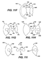
- instrument 10L is similar to instrument 10 of FIGS. 1-10 except that instrument 10L includes a different attachment mechanism 19L.
- the instrument 10L includes a first component 14L having a base 64L including a protrusion 60L having a stem portion 29L and a cylindrical portion 31 L extending from the stem portion 29L.
- Instrument 10L further includes a second component 18L defining a slot 62L which cooperates with the protrusion 60L of the first component 14L.
- instrument 10M is similar to the instrument 10L of FIG. 11 G except that the attachment mechanism is reversed.
- the instrument 10M includes an attachment mechanism 19M including a protrusion 62M extending from second component 18M.
- the protrusion 62M includes a stem 29M to which a cylindrical portion 31M extends.
- the protrusion 62M cooperates with a slot 60M formed in base 64M of first component 14M.
- instrument 10H is similar to the instruments 10L and 10M of FIGS. 11G and 11H, respectively.
- the instrument 10N includes an attachment mechanism 19N having a three part construction.
- the instrument 19N includes a first component 14N having a base 64N to which a first slot 60N is formed.
- the instrument 10N further includes a second component 18N to which a second slot 62N is formed.
- the slots 60N and 62N are connected with a connector 33N having opposed protrusions 35N and extending from the opposed ends of centre portion 37N of the connector 33N.
- One protrusion 35N cooperates with first slot 60N while the other protrusion 35N cooperates with second slot 62N.
- the connector 33N may either be resilient or be permitted to articulate during the operation of the instrument 10N.
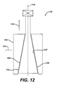
- instrument 110 is similar to instrument 10 of FIGS. 1-10 except that the instrument 110 includes a first component 114 having a base 164 defining external periphery 139 which has a reversed angle to that of the base 64 of the instrument 10 of FIGS 1-10.
- the instrument 110 further includes a second component 118 having an internal periphery 137 which cooperates with the external periphery 139 of the base 164. As shown in FIG.
- the instrument of 110 of FIG. 12 operates in an opposite manner than that of the instrument 10 of FIGS. 1-10.
- FIG. 13 another embodiment of the present invention in the form of instrument 210 is shown.
- the instrument 210 is similar to the instrument 10 of FIGS. 1-10 except that it includes a tamping portion 248 in the form of a solitary component. As shown in FIG. 13, the instrument 210 includes a solitary tamping portion 248 in the form of a collet 218.
- the second component 218 is in the form of a collet which cooperates with first component 218.
- Slots 217 are formed in periphery 250 of the second component 218.
- the slots 217 may extend from opposed ends of the collet 218.
- the slots 217 permit the expansion of the collet 218 in the direction of arrow 241 as the first component 214 advances in the direction of arrow 234 with respect to the collet 218.
- Instrument 310 is similar to instrument 210 of FIG. 13 except that the instrument 310 includes a collet 318 that includes slots 317 formed in only one end of the collet 318.
- the collet 318 similar to the collet 318, cooperates with a first component 314 to provide for motion of the collet 318 in the direction of arrow 341 as the first component 314 advances in the direction of arrow 334.
- Instrument 410 is similar to instruments 210 and 310 of FIGS. 13 and 14, respectively in that instrument 410 relies on a resilient tamping portion.
- the instrument 410 includes a tamping portion 448 including a plurality of spaced apart split rings 419 which combine to form the tamping portion 448.
- the rings 419 of the tamping portion 448 cooperate with first component 414. As first component 414 advances distally in the direction of arrow 434, the rings 419 expand outwardly in the direction of arrow 441, thereby compacting the bone material.
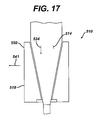
- instrument 510 is similar to instrument 210 of FIG. 13 except that in the place of a collet with split components, a collet is provided made of a resilient material.
- the instrument 510 includes a second component 518 made of a resilient material, for example a polymer, which is mated to the first component 514.
- the resilient material in the second component 518 causes periphery 550 of the second component 518 to advance outwardly in the direction of arrow 541.
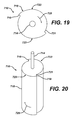
- Instrument 610 is similar to instrument 510 of FIG. 17 in that the instrument 610 includes a second component 618 made of a resilient material.
- the resilient material of the second component 618 is expanded in a different method than that of the resilient material in the second component 518 of the instrument 510 of FIG. 17.
- the first component 614 cooperates with a piston 615 to advance a fluid 617 for expanding the second component 618.
- the piston 615 is advanced in a similar direction compressing the fluid 618 outwardly in the direction of arrows 641 to expand the second component 618 thereby compacting the bone material.
- Instrument 710 includes a second component 718 extending distally from first component 714.
- the second component 718 is generally in the form of a cylinder but includes segments 723 extending outwardly from the second component 718.
- the segment 723 include a leading edge 721 and a trailing edge 719 which extends readily outward from the leading edge 721.
- the second component 718 advances in the direction of arrow 725 causing bone material to advance from the leading edge 721 to a trailing edge 719 which provides for the compacting of the bone material.
- Method 800 includes the first step 810 of cutting an incision in the patient.
- the method 800 further includes a second step 820 of preparing a cavity in the long bone.
- the method 800 further includes a third step 830 of providing an instrument for compacting bone material having a first component defining a longitudinal axis thereof and a second component moveable at least partially in the radial direction outwardly from the longitudinal axis of the first component.
- the method 800 further includes a fourth step 840 of placing the instrument in a cavity and a fifth step 850 of compacting the bone material in the cavity.
Landscapes
- Health & Medical Sciences (AREA)
- Orthopedic Medicine & Surgery (AREA)
- Life Sciences & Earth Sciences (AREA)
- General Health & Medical Sciences (AREA)
- Surgery (AREA)
- Transplantation (AREA)
- Veterinary Medicine (AREA)
- Engineering & Computer Science (AREA)
- Biomedical Technology (AREA)
- Heart & Thoracic Surgery (AREA)
- Public Health (AREA)
- Animal Behavior & Ethology (AREA)
- Oral & Maxillofacial Surgery (AREA)
- Vascular Medicine (AREA)
- Cardiology (AREA)
- Nuclear Medicine, Radiotherapy & Molecular Imaging (AREA)
- Physical Education & Sports Medicine (AREA)
- Medical Informatics (AREA)
- Molecular Biology (AREA)
- Prostheses (AREA)
- Materials For Medical Uses (AREA)
Applications Claiming Priority (2)
| Application Number | Priority Date | Filing Date | Title |
|---|---|---|---|
| US10/671,820 US7799029B2 (en) | 2003-09-26 | 2003-09-26 | Radial impaction bone tamp and associated method |
| US671820 | 2003-09-26 |
Publications (3)
| Publication Number | Publication Date |
|---|---|
| EP1523965A2 true EP1523965A2 (de) | 2005-04-20 |
| EP1523965A3 EP1523965A3 (de) | 2005-11-09 |
| EP1523965B1 EP1523965B1 (de) | 2010-10-27 |
Family
ID=34376195
Family Applications (1)
| Application Number | Title | Priority Date | Filing Date |
|---|---|---|---|
| EP04255788A Expired - Lifetime EP1523965B1 (de) | 2003-09-26 | 2004-09-22 | Medizinischer Knochenverdichter |
Country Status (4)
| Country | Link |
|---|---|
| US (1) | US7799029B2 (de) |
| EP (1) | EP1523965B1 (de) |
| AT (1) | ATE485793T1 (de) |
| DE (1) | DE602004029751D1 (de) |
Families Citing this family (15)
| Publication number | Priority date | Publication date | Assignee | Title |
|---|---|---|---|---|
| US7833228B1 (en) * | 2004-01-05 | 2010-11-16 | Biomet Manufacturing Corp. | Method and instrumentation for performing minimally invasive hip arthroplasty |
| US7615052B2 (en) * | 2005-04-29 | 2009-11-10 | Warsaw Orthopedic, Inc. | Surgical instrument and method |
| WO2008020896A1 (en) * | 2006-08-07 | 2008-02-21 | Strathmore Industries Inc. | Bone tamp apparatus and method |
| US20080177266A1 (en) * | 2006-10-18 | 2008-07-24 | Warsaw Orthopedic, Inc. | Adjustable height rasp |
| WO2008069800A1 (en) * | 2006-12-07 | 2008-06-12 | Anatol Podolsky | Method and apparatus for total hip replacement |
| US8974540B2 (en) | 2006-12-07 | 2015-03-10 | Ihip Surgical, Llc | Method and apparatus for attachment in a modular hip replacement or fracture fixation device |
| US8579985B2 (en) | 2006-12-07 | 2013-11-12 | Ihip Surgical, Llc | Method and apparatus for hip replacement |
| CA2725182A1 (en) * | 2007-05-22 | 2008-12-18 | Vg Innovations, Inc. | Method and apparatus for spinal facet fusion |
| US20090112326A1 (en) * | 2007-10-24 | 2009-04-30 | Disc Dynamics, Inc. | In situ adjustable dynamic intervertebral implant |
| US8348953B2 (en) * | 2008-01-10 | 2013-01-08 | Peter Brehm | Method and apparatus for impacting bone material |
| USD597669S1 (en) | 2009-03-13 | 2009-08-04 | Orthopedic Development Corporation | Surgical impactor |
| US9138243B2 (en) * | 2011-03-25 | 2015-09-22 | Orthopaedic International, Inc. | Bone compactor |
| US10575781B2 (en) | 2016-05-24 | 2020-03-03 | AOD Holdings, LLC. | Hip broach with embedded sensor and a feedback broach system |
| CA3027227A1 (en) | 2016-06-23 | 2017-12-28 | VGI Medical, LLC | Method and apparatus for spinal facet fusion |
| JP7165214B2 (ja) * | 2018-06-25 | 2022-11-02 | コンメッド コーポレーション | 靭帯修正システム |
Citations (1)
| Publication number | Priority date | Publication date | Assignee | Title |
|---|---|---|---|---|
| DE3630069C1 (en) | 1986-09-04 | 1988-01-28 | Aesculap Werke Ag | Surgical instrument for compacting spongy substance |
Family Cites Families (55)
| Publication number | Priority date | Publication date | Assignee | Title |
|---|---|---|---|---|
| US832201A (en) * | 1904-12-12 | 1906-10-02 | Samuel L Kistler | Dilator. |
| US2620537A (en) * | 1938-11-15 | 1952-12-09 | Jean E F Gobin-Daude | Resilient fastener formed of folded metallic strips |
| US2601803A (en) * | 1948-11-04 | 1952-07-01 | Falcon Fasteners Inc | Fastening means |
| DE2112139B2 (de) * | 1971-03-13 | 1973-02-01 | Fischer, Artur, 7241 Tumhngen | Huelsenfoermiges verbindungselement fuer die kompressions-osteosynthese bei roehrenknochenfrakturen |
| US3921496A (en) * | 1974-11-04 | 1975-11-25 | J Frank Helderman | Fastener assembly |
| IL53703A (en) * | 1977-12-28 | 1979-10-31 | Aginsky Yacov | Intramedullary nails |
| EP0006314A1 (de) | 1978-05-31 | 1980-01-09 | Thomas Gordon Wadsworth | Ellenbogenprothese und Instrumente zur Implantation der Prothese |
| US4237875A (en) * | 1979-02-23 | 1980-12-09 | Towmotor Corporation | Dynamic intramedullary compression nailing |
| US4275717A (en) * | 1979-07-27 | 1981-06-30 | Zimmer Usa, Inc. | Intramedullary fixation device for fractured tubular bones |
| US5222985B1 (en) | 1982-04-19 | 2000-10-24 | Tranguil Prospects Ltd | Implantation of articulating joint prosthesis |
| US4462394A (en) * | 1982-05-03 | 1984-07-31 | Howmedica, Inc. | Intramedullary canal seal for cement pressurization |
| US4519100A (en) * | 1982-09-30 | 1985-05-28 | Orthopedic Equipment Co. Inc. | Distal locking intramedullary nail |
| US4474177A (en) | 1983-03-09 | 1984-10-02 | Wright Manufacturing Company | Method and apparatus for shaping a distal femoral surface |
| US4552136A (en) | 1983-10-19 | 1985-11-12 | Howmedica, Inc. | Femoral rasp |
| US4697584A (en) | 1984-10-12 | 1987-10-06 | Darrel W. Haynes | Device and method for plugging an intramedullary bone canal |
| US5089004A (en) | 1988-01-19 | 1992-02-18 | Osteonics Corp. | Prosthetic implant procedure and femoral broach therefor |
| US5147408A (en) | 1988-10-07 | 1992-09-15 | Pfizer Hospital Products Group, Inc. | Prosthetic device and method of implantation |
| US5234433A (en) | 1989-09-26 | 1993-08-10 | Kirschner Medical Corporation | Method and instrumentation for unicompartmental total knee arthroplasty |
| US5057103A (en) * | 1990-05-01 | 1991-10-15 | Davis Emsley A | Compressive intramedullary nail |
| US5180388A (en) | 1990-06-28 | 1993-01-19 | American Cyanamid Company | Bone pinning system |
| US5047035A (en) | 1990-08-10 | 1991-09-10 | Mikhail Michael W E | System for performing hip prosthesis revision surgery |
| US5108405A (en) | 1990-08-10 | 1992-04-28 | Mikhail Michael W E | System for performing hip prosethesis revision surgery |
| US5129283A (en) | 1990-08-31 | 1992-07-14 | Eaton Corporation | Push to turn mechanism |
| US5222955A (en) | 1991-02-08 | 1993-06-29 | Mikhail Michael W E | Method for implanting a patellar prosthesis |
| US5197967A (en) | 1991-04-02 | 1993-03-30 | Synthes (U.S.A.) | Trephine instrument and method for cutting annular holes |
| SE510358C2 (sv) | 1992-02-20 | 1999-05-17 | Goesta Ullmark | Anordning för användning vid transplantation av benvävnadsmaterial i ett hålrum i ben |
| IT1257859B (it) | 1992-07-13 | 1996-02-13 | Endoprotesi per osteosintesi del femore prossimale | |
| US5324293A (en) | 1992-11-13 | 1994-06-28 | U.S. Medical Products, Inc. | Surgical broach and broach holder |
| US5312412A (en) | 1993-02-03 | 1994-05-17 | Whipple Terry L | Fixation alignment guide for surgical use |
| EP0700272B1 (de) | 1993-05-27 | 1999-01-07 | Howmedica Inc. | Flexible reibahle für einen markkanal |
| WO1995014433A1 (en) | 1993-11-24 | 1995-06-01 | Orthopaedic Innovations, Inc. | Cannulated instrumentation for total joint arthroplasty and method of use |
| US6248110B1 (en) | 1994-01-26 | 2001-06-19 | Kyphon, Inc. | Systems and methods for treating fractured or diseased bone using expandable bodies |
| GB9420050D0 (en) | 1994-10-05 | 1994-11-16 | Howmedica | Apparatus and method for implanting a prosthesis |
| US5697932A (en) | 1994-11-09 | 1997-12-16 | Osteonics Corp. | Bone graft delivery system and method |
| WO1996025113A1 (en) | 1995-02-16 | 1996-08-22 | Johnson Lanny L | Method and apparatus for forming a centered bore for the femoral stem of a hip prosthesis |
| US5658293A (en) | 1995-10-10 | 1997-08-19 | Zimmer, Inc. | Guide platform associated with intramedullary rod |
| US5766178A (en) | 1996-12-13 | 1998-06-16 | Howmedia Inc. | Bone plug |
| US5755720A (en) | 1997-01-03 | 1998-05-26 | Mikhail Michael W E | Method and apparatus for performing hip prosthesis surgery |
| US5718707A (en) | 1997-01-22 | 1998-02-17 | Mikhail; W. E. Michael | Method and apparatus for positioning and compacting bone graft |
| US5935169A (en) | 1997-02-13 | 1999-08-10 | Chan; Kwan-Ho | Bone cement plug for deployment in a bone canal |
| GB9714003D0 (en) | 1997-07-02 | 1997-09-10 | Howmedica | Apparatus for impacting bone chips in a bone canal |
| US6013080A (en) | 1997-10-30 | 2000-01-11 | Johnson & Johnson Professional, Inc. | Tamp with horizontal steps used for impaction bone grafting in revision femur |
| US6149669A (en) * | 1997-10-30 | 2000-11-21 | Li Medical Technologies, Inc. | Surgical fastener assembly method of use |
| US6139583A (en) | 1998-06-12 | 2000-10-31 | Johnson; Lanny L. | Femoral prosthesis |
| US6126659A (en) | 1998-09-30 | 2000-10-03 | Depuy Orthopaedics, Inc. | Impaction instruments |
| US6186716B1 (en) * | 1998-11-12 | 2001-02-13 | Westerlund Products Corporation | Anchor bolt |
| US6270502B1 (en) | 1998-12-11 | 2001-08-07 | Smith & Nephew, Inc. | Methods and instruments for performing radial impacting |
| US6143030A (en) | 1999-03-26 | 2000-11-07 | Bristol-Myers Squibb Co. | Impaction allograft form and method of orthopaedic surgery using same |
| US6228092B1 (en) | 1999-07-29 | 2001-05-08 | W. E. Michael Mikhail | System for performing hip prosthesis surgery |
| GB9921099D0 (en) | 1999-09-08 | 1999-11-10 | Depuy Int Ltd | A tamp assembly |
| DE19949385C2 (de) | 1999-10-13 | 2002-05-08 | Geza Lakos | Vorrichtung zum Knochenverdichten für zahnärztlichimplantologische Zwecke |
| US6309220B1 (en) | 2000-10-20 | 2001-10-30 | Neal B. Gittleman | Bone distention and condensation dental implant distractor apparatus and method |
| GB0028445D0 (en) | 2000-11-22 | 2001-01-10 | Depuy Int Ltd | A tamp assembly |
| US6702823B2 (en) | 2002-01-14 | 2004-03-09 | Hit Medica S.R.L. | Device for identifying the position of intramedullary nail securement screw holes |
| US20040087994A1 (en) * | 2002-08-29 | 2004-05-06 | Loubert Suddaby | Mechanical bone tamping device for repair of osteoporotic bone fractures |
-
2003
- 2003-09-26 US US10/671,820 patent/US7799029B2/en not_active Expired - Lifetime
-
2004
- 2004-09-22 DE DE602004029751T patent/DE602004029751D1/de not_active Expired - Lifetime
- 2004-09-22 AT AT04255788T patent/ATE485793T1/de not_active IP Right Cessation
- 2004-09-22 EP EP04255788A patent/EP1523965B1/de not_active Expired - Lifetime
Patent Citations (1)
| Publication number | Priority date | Publication date | Assignee | Title |
|---|---|---|---|---|
| DE3630069C1 (en) | 1986-09-04 | 1988-01-28 | Aesculap Werke Ag | Surgical instrument for compacting spongy substance |
Also Published As
| Publication number | Publication date |
|---|---|
| EP1523965A3 (de) | 2005-11-09 |
| DE602004029751D1 (de) | 2010-12-09 |
| US20050070898A1 (en) | 2005-03-31 |
| EP1523965B1 (de) | 2010-10-27 |
| ATE485793T1 (de) | 2010-11-15 |
| US7799029B2 (en) | 2010-09-21 |
Similar Documents
| Publication | Publication Date | Title |
|---|---|---|
| AU772169B2 (en) | Methods and instruments for radial bone impacting | |
| CN102014800B (zh) | 局部关节表面置换植入物、仪器和方法 | |
| US7329284B2 (en) | Concave resurfacing prosthesis | |
| EP1523965B1 (de) | Medizinischer Knochenverdichter | |
| US20040193275A1 (en) | Prosthetic implant, trial and associated method | |
| US20040254646A1 (en) | Provisional coupling mechanism | |
| AU2008203510A1 (en) | Method for repairing defects in bone | |
| US20150100061A1 (en) | Canal sizer and associated method | |
| WO2017053183A1 (en) | Acetabular cup taper cover and liner trial spacer | |
| CN118119362A (zh) | 内假体膝关节植入物的胫骨部件、用于胫骨部件的套件和器械以及使用方法 | |
| US11751999B2 (en) | Trial radial head implant | |
| US5782922A (en) | Method and apparatus for replacing the capitellum | |
| EP1413263A1 (de) | Prothetisches Implantat | |
| US6656188B2 (en) | Tamp assembly | |
| US20050203524A1 (en) | Bone preserving total hip arthroplasty using autograft | |
| AU2008200827B2 (en) | Concave resurfacing prosthesis |
Legal Events
| Date | Code | Title | Description |
|---|---|---|---|
| PUAI | Public reference made under article 153(3) epc to a published international application that has entered the european phase |
Free format text: ORIGINAL CODE: 0009012 |
|
| AK | Designated contracting states |
Kind code of ref document: A2 Designated state(s): AT BE BG CH CY CZ DE DK EE ES FI FR GB GR HU IE IT LI LU MC NL PL PT RO SE SI SK TR |
|
| AX | Request for extension of the european patent |
Extension state: AL HR LT LV MK |
|
| PUAL | Search report despatched |
Free format text: ORIGINAL CODE: 0009013 |
|
| AK | Designated contracting states |
Kind code of ref document: A3 Designated state(s): AT BE BG CH CY CZ DE DK EE ES FI FR GB GR HU IE IT LI LU MC NL PL PT RO SE SI SK TR |
|
| AX | Request for extension of the european patent |
Extension state: AL HR LT LV MK |
|
| 17P | Request for examination filed |
Effective date: 20060321 |
|
| AKX | Designation fees paid |
Designated state(s): AT BE BG CH CY CZ DE DK EE ES FI FR GB GR HU IE IT LI LU MC NL PL PT RO SE SI SK TR |
|
| 17Q | First examination report despatched |
Effective date: 20071022 |
|
| RTI1 | Title (correction) |
Free format text: MEDICAL BONE IMPACTION TAMP |
|
| GRAP | Despatch of communication of intention to grant a patent |
Free format text: ORIGINAL CODE: EPIDOSNIGR1 |
|
| GRAS | Grant fee paid |
Free format text: ORIGINAL CODE: EPIDOSNIGR3 |
|
| GRAA | (expected) grant |
Free format text: ORIGINAL CODE: 0009210 |
|
| AK | Designated contracting states |
Kind code of ref document: B1 Designated state(s): AT BE BG CH CY CZ DE DK EE ES FI FR GB GR HU IE IT LI LU MC NL PL PT RO SE SI SK TR |
|
| REG | Reference to a national code |
Ref country code: GB Ref legal event code: FG4D |
|
| REG | Reference to a national code |
Ref country code: CH Ref legal event code: EP |
|
| REG | Reference to a national code |
Ref country code: CH Ref legal event code: NV Representative=s name: E. BLUM & CO. AG PATENT- UND MARKENANWAELTE VSP |
|
| REG | Reference to a national code |
Ref country code: IE Ref legal event code: FG4D |
|
| REF | Corresponds to: |
Ref document number: 602004029751 Country of ref document: DE Date of ref document: 20101209 Kind code of ref document: P |
|
| REG | Reference to a national code |
Ref country code: NL Ref legal event code: VDEP Effective date: 20101027 |
|
| PG25 | Lapsed in a contracting state [announced via postgrant information from national office to epo] |
Ref country code: NL Free format text: LAPSE BECAUSE OF FAILURE TO SUBMIT A TRANSLATION OF THE DESCRIPTION OR TO PAY THE FEE WITHIN THE PRESCRIBED TIME-LIMIT Effective date: 20101027 Ref country code: PT Free format text: LAPSE BECAUSE OF FAILURE TO SUBMIT A TRANSLATION OF THE DESCRIPTION OR TO PAY THE FEE WITHIN THE PRESCRIBED TIME-LIMIT Effective date: 20110228 Ref country code: SE Free format text: LAPSE BECAUSE OF FAILURE TO SUBMIT A TRANSLATION OF THE DESCRIPTION OR TO PAY THE FEE WITHIN THE PRESCRIBED TIME-LIMIT Effective date: 20101027 Ref country code: FI Free format text: LAPSE BECAUSE OF FAILURE TO SUBMIT A TRANSLATION OF THE DESCRIPTION OR TO PAY THE FEE WITHIN THE PRESCRIBED TIME-LIMIT Effective date: 20101027 Ref country code: AT Free format text: LAPSE BECAUSE OF FAILURE TO SUBMIT A TRANSLATION OF THE DESCRIPTION OR TO PAY THE FEE WITHIN THE PRESCRIBED TIME-LIMIT Effective date: 20101027 Ref country code: SI Free format text: LAPSE BECAUSE OF FAILURE TO SUBMIT A TRANSLATION OF THE DESCRIPTION OR TO PAY THE FEE WITHIN THE PRESCRIBED TIME-LIMIT Effective date: 20101027 Ref country code: BG Free format text: LAPSE BECAUSE OF FAILURE TO SUBMIT A TRANSLATION OF THE DESCRIPTION OR TO PAY THE FEE WITHIN THE PRESCRIBED TIME-LIMIT Effective date: 20110127 |
|
| PG25 | Lapsed in a contracting state [announced via postgrant information from national office to epo] |
Ref country code: BE Free format text: LAPSE BECAUSE OF FAILURE TO SUBMIT A TRANSLATION OF THE DESCRIPTION OR TO PAY THE FEE WITHIN THE PRESCRIBED TIME-LIMIT Effective date: 20101027 Ref country code: GR Free format text: LAPSE BECAUSE OF FAILURE TO SUBMIT A TRANSLATION OF THE DESCRIPTION OR TO PAY THE FEE WITHIN THE PRESCRIBED TIME-LIMIT Effective date: 20110128 |
|
| PG25 | Lapsed in a contracting state [announced via postgrant information from national office to epo] |
Ref country code: EE Free format text: LAPSE BECAUSE OF FAILURE TO SUBMIT A TRANSLATION OF THE DESCRIPTION OR TO PAY THE FEE WITHIN THE PRESCRIBED TIME-LIMIT Effective date: 20101027 Ref country code: ES Free format text: LAPSE BECAUSE OF FAILURE TO SUBMIT A TRANSLATION OF THE DESCRIPTION OR TO PAY THE FEE WITHIN THE PRESCRIBED TIME-LIMIT Effective date: 20110207 Ref country code: CZ Free format text: LAPSE BECAUSE OF FAILURE TO SUBMIT A TRANSLATION OF THE DESCRIPTION OR TO PAY THE FEE WITHIN THE PRESCRIBED TIME-LIMIT Effective date: 20101027 |
|
| PG25 | Lapsed in a contracting state [announced via postgrant information from national office to epo] |
Ref country code: SK Free format text: LAPSE BECAUSE OF FAILURE TO SUBMIT A TRANSLATION OF THE DESCRIPTION OR TO PAY THE FEE WITHIN THE PRESCRIBED TIME-LIMIT Effective date: 20101027 Ref country code: DK Free format text: LAPSE BECAUSE OF FAILURE TO SUBMIT A TRANSLATION OF THE DESCRIPTION OR TO PAY THE FEE WITHIN THE PRESCRIBED TIME-LIMIT Effective date: 20101027 Ref country code: RO Free format text: LAPSE BECAUSE OF FAILURE TO SUBMIT A TRANSLATION OF THE DESCRIPTION OR TO PAY THE FEE WITHIN THE PRESCRIBED TIME-LIMIT Effective date: 20101027 Ref country code: PL Free format text: LAPSE BECAUSE OF FAILURE TO SUBMIT A TRANSLATION OF THE DESCRIPTION OR TO PAY THE FEE WITHIN THE PRESCRIBED TIME-LIMIT Effective date: 20101027 |
|
| PLBE | No opposition filed within time limit |
Free format text: ORIGINAL CODE: 0009261 |
|
| STAA | Information on the status of an ep patent application or granted ep patent |
Free format text: STATUS: NO OPPOSITION FILED WITHIN TIME LIMIT |
|
| 26N | No opposition filed |
Effective date: 20110728 |
|
| REG | Reference to a national code |
Ref country code: DE Ref legal event code: R097 Ref document number: 602004029751 Country of ref document: DE Effective date: 20110728 |
|
| PG25 | Lapsed in a contracting state [announced via postgrant information from national office to epo] |
Ref country code: IT Free format text: LAPSE BECAUSE OF FAILURE TO SUBMIT A TRANSLATION OF THE DESCRIPTION OR TO PAY THE FEE WITHIN THE PRESCRIBED TIME-LIMIT Effective date: 20101027 |
|
| PG25 | Lapsed in a contracting state [announced via postgrant information from national office to epo] |
Ref country code: MC Free format text: LAPSE BECAUSE OF NON-PAYMENT OF DUE FEES Effective date: 20110930 |
|
| PG25 | Lapsed in a contracting state [announced via postgrant information from national office to epo] |
Ref country code: LU Free format text: LAPSE BECAUSE OF NON-PAYMENT OF DUE FEES Effective date: 20110922 Ref country code: CY Free format text: LAPSE BECAUSE OF EXPIRATION OF PROTECTION Effective date: 20101027 |
|
| PG25 | Lapsed in a contracting state [announced via postgrant information from national office to epo] |
Ref country code: TR Free format text: LAPSE BECAUSE OF FAILURE TO SUBMIT A TRANSLATION OF THE DESCRIPTION OR TO PAY THE FEE WITHIN THE PRESCRIBED TIME-LIMIT Effective date: 20101027 |
|
| PG25 | Lapsed in a contracting state [announced via postgrant information from national office to epo] |
Ref country code: HU Free format text: LAPSE BECAUSE OF FAILURE TO SUBMIT A TRANSLATION OF THE DESCRIPTION OR TO PAY THE FEE WITHIN THE PRESCRIBED TIME-LIMIT Effective date: 20101027 |
|
| REG | Reference to a national code |
Ref country code: FR Ref legal event code: PLFP Year of fee payment: 13 |
|
| REG | Reference to a national code |
Ref country code: FR Ref legal event code: PLFP Year of fee payment: 14 |
|
| REG | Reference to a national code |
Ref country code: FR Ref legal event code: PLFP Year of fee payment: 15 |
|
| PGFP | Annual fee paid to national office [announced via postgrant information from national office to epo] |
Ref country code: IE Payment date: 20220809 Year of fee payment: 19 Ref country code: GB Payment date: 20220804 Year of fee payment: 19 Ref country code: DE Payment date: 20220609 Year of fee payment: 19 |
|
| PGFP | Annual fee paid to national office [announced via postgrant information from national office to epo] |
Ref country code: FR Payment date: 20220808 Year of fee payment: 19 |
|
| PGFP | Annual fee paid to national office [announced via postgrant information from national office to epo] |
Ref country code: CH Payment date: 20221001 Year of fee payment: 19 |
|
| REG | Reference to a national code |
Ref country code: DE Ref legal event code: R119 Ref document number: 602004029751 Country of ref document: DE |
|
| REG | Reference to a national code |
Ref country code: CH Ref legal event code: PL |
|
| GBPC | Gb: european patent ceased through non-payment of renewal fee |
Effective date: 20230922 |
|
| REG | Reference to a national code |
Ref country code: IE Ref legal event code: MM4A |
|
| PG25 | Lapsed in a contracting state [announced via postgrant information from national office to epo] |
Ref country code: IE Free format text: LAPSE BECAUSE OF NON-PAYMENT OF DUE FEES Effective date: 20230922 |
|
| PG25 | Lapsed in a contracting state [announced via postgrant information from national office to epo] |
Ref country code: GB Free format text: LAPSE BECAUSE OF NON-PAYMENT OF DUE FEES Effective date: 20230922 |
|
| PG25 | Lapsed in a contracting state [announced via postgrant information from national office to epo] |
Ref country code: CH Free format text: LAPSE BECAUSE OF NON-PAYMENT OF DUE FEES Effective date: 20230930 |
|
| PG25 | Lapsed in a contracting state [announced via postgrant information from national office to epo] |
Ref country code: IE Free format text: LAPSE BECAUSE OF NON-PAYMENT OF DUE FEES Effective date: 20230922 Ref country code: GB Free format text: LAPSE BECAUSE OF NON-PAYMENT OF DUE FEES Effective date: 20230922 Ref country code: FR Free format text: LAPSE BECAUSE OF NON-PAYMENT OF DUE FEES Effective date: 20230930 Ref country code: DE Free format text: LAPSE BECAUSE OF NON-PAYMENT OF DUE FEES Effective date: 20240403 Ref country code: CH Free format text: LAPSE BECAUSE OF NON-PAYMENT OF DUE FEES Effective date: 20230930 |