EP1523948A1 - Dispositif d'accès chirurgical et son procédé de fabrication - Google Patents
Dispositif d'accès chirurgical et son procédé de fabrication Download PDFInfo
- Publication number
- EP1523948A1 EP1523948A1 EP04024600A EP04024600A EP1523948A1 EP 1523948 A1 EP1523948 A1 EP 1523948A1 EP 04024600 A EP04024600 A EP 04024600A EP 04024600 A EP04024600 A EP 04024600A EP 1523948 A1 EP1523948 A1 EP 1523948A1
- Authority
- EP
- European Patent Office
- Prior art keywords
- tubular member
- base
- housing
- surgical access
- access system
- Prior art date
- Legal status (The legal status is an assumption and is not a legal conclusion. Google has not performed a legal analysis and makes no representation as to the accuracy of the status listed.)
- Granted
Links
- 238000004519 manufacturing process Methods 0.000 title claims abstract description 9
- 238000000034 method Methods 0.000 claims abstract description 43
- 230000008569 process Effects 0.000 claims abstract description 23
- 239000000463 material Substances 0.000 claims abstract description 16
- 229920001971 elastomer Polymers 0.000 claims description 14
- 239000000806 elastomer Substances 0.000 claims description 14
- 238000003780 insertion Methods 0.000 claims description 5
- 230000037431 insertion Effects 0.000 claims description 5
- 238000001125 extrusion Methods 0.000 claims description 2
- JOYRKODLDBILNP-UHFFFAOYSA-N Ethyl urethane Chemical compound CCOC(N)=O JOYRKODLDBILNP-UHFFFAOYSA-N 0.000 description 9
- 230000010339 dilation Effects 0.000 description 5
- 238000012978 minimally invasive surgical procedure Methods 0.000 description 4
- 239000004810 polytetrafluoroethylene Substances 0.000 description 4
- 229920001343 polytetrafluoroethylene Polymers 0.000 description 4
- 238000001356 surgical procedure Methods 0.000 description 4
- 210000001015 abdomen Anatomy 0.000 description 3
- 208000014674 injury Diseases 0.000 description 3
- 241001631457 Cannula Species 0.000 description 2
- 210000003815 abdominal wall Anatomy 0.000 description 2
- 239000013536 elastomeric material Substances 0.000 description 2
- 238000010438 heat treatment Methods 0.000 description 2
- 239000012528 membrane Substances 0.000 description 2
- 238000012986 modification Methods 0.000 description 2
- 230000004048 modification Effects 0.000 description 2
- 239000004753 textile Substances 0.000 description 2
- 230000008733 trauma Effects 0.000 description 2
- 239000004698 Polyethylene Substances 0.000 description 1
- RTAQQCXQSZGOHL-UHFFFAOYSA-N Titanium Chemical compound [Ti] RTAQQCXQSZGOHL-UHFFFAOYSA-N 0.000 description 1
- 208000027418 Wounds and injury Diseases 0.000 description 1
- 230000003187 abdominal effect Effects 0.000 description 1
- 239000000853 adhesive Substances 0.000 description 1
- 230000001070 adhesive effect Effects 0.000 description 1
- 238000004873 anchoring Methods 0.000 description 1
- 230000008901 benefit Effects 0.000 description 1
- 210000000038 chest Anatomy 0.000 description 1
- 239000011248 coating agent Substances 0.000 description 1
- 238000000576 coating method Methods 0.000 description 1
- 230000008878 coupling Effects 0.000 description 1
- 238000010168 coupling process Methods 0.000 description 1
- 238000005859 coupling reaction Methods 0.000 description 1
- 230000006378 damage Effects 0.000 description 1
- 238000012976 endoscopic surgical procedure Methods 0.000 description 1
- 239000004744 fabric Substances 0.000 description 1
- 239000006260 foam Substances 0.000 description 1
- 239000003292 glue Substances 0.000 description 1
- 230000002401 inhibitory effect Effects 0.000 description 1
- 210000003127 knee Anatomy 0.000 description 1
- 238000002357 laparoscopic surgery Methods 0.000 description 1
- 230000000670 limiting effect Effects 0.000 description 1
- 229910052751 metal Inorganic materials 0.000 description 1
- 239000002184 metal Substances 0.000 description 1
- 150000002739 metals Chemical class 0.000 description 1
- 230000037368 penetrate the skin Effects 0.000 description 1
- 231100000435 percutaneous penetration Toxicity 0.000 description 1
- 230000002093 peripheral effect Effects 0.000 description 1
- 239000004033 plastic Substances 0.000 description 1
- 229920003023 plastic Polymers 0.000 description 1
- -1 polyethylene Polymers 0.000 description 1
- 229920000573 polyethylene Polymers 0.000 description 1
- 229920000642 polymer Polymers 0.000 description 1
- 238000011084 recovery Methods 0.000 description 1
- 230000002829 reductive effect Effects 0.000 description 1
- 230000000717 retained effect Effects 0.000 description 1
- 229910001220 stainless steel Inorganic materials 0.000 description 1
- 239000010935 stainless steel Substances 0.000 description 1
- 210000000115 thoracic cavity Anatomy 0.000 description 1
- 239000010936 titanium Substances 0.000 description 1
- 229910052719 titanium Inorganic materials 0.000 description 1
- 230000007704 transition Effects 0.000 description 1
- 210000001835 viscera Anatomy 0.000 description 1
Images

Classifications
-
- A—HUMAN NECESSITIES
- A61—MEDICAL OR VETERINARY SCIENCE; HYGIENE
- A61B—DIAGNOSIS; SURGERY; IDENTIFICATION
- A61B17/00—Surgical instruments, devices or methods
- A61B17/34—Trocars; Puncturing needles
- A61B17/3417—Details of tips or shafts, e.g. grooves, expandable, bendable; Multiple coaxial sliding cannulas, e.g. for dilating
- A61B17/3421—Cannulas
- A61B17/3431—Cannulas being collapsible, e.g. made of thin flexible material
-
- A—HUMAN NECESSITIES
- A61—MEDICAL OR VETERINARY SCIENCE; HYGIENE
- A61B—DIAGNOSIS; SURGERY; IDENTIFICATION
- A61B17/00—Surgical instruments, devices or methods
- A61B17/34—Trocars; Puncturing needles
- A61B17/3417—Details of tips or shafts, e.g. grooves, expandable, bendable; Multiple coaxial sliding cannulas, e.g. for dilating
- A61B17/3421—Cannulas
- A61B17/3439—Cannulas with means for changing the inner diameter of the cannula, e.g. expandable
-
- A—HUMAN NECESSITIES
- A61—MEDICAL OR VETERINARY SCIENCE; HYGIENE
- A61B—DIAGNOSIS; SURGERY; IDENTIFICATION
- A61B17/00—Surgical instruments, devices or methods
- A61B17/34—Trocars; Puncturing needles
- A61B17/3462—Trocars; Puncturing needles with means for changing the diameter or the orientation of the entrance port of the cannula, e.g. for use with different-sized instruments, reduction ports, adapter seals
-
- A—HUMAN NECESSITIES
- A61—MEDICAL OR VETERINARY SCIENCE; HYGIENE
- A61B—DIAGNOSIS; SURGERY; IDENTIFICATION
- A61B17/00—Surgical instruments, devices or methods
- A61B2017/00526—Methods of manufacturing
-
- A—HUMAN NECESSITIES
- A61—MEDICAL OR VETERINARY SCIENCE; HYGIENE
- A61B—DIAGNOSIS; SURGERY; IDENTIFICATION
- A61B17/00—Surgical instruments, devices or methods
- A61B17/34—Trocars; Puncturing needles
- A61B2017/347—Locking means, e.g. for locking instrument in cannula
-
- A—HUMAN NECESSITIES
- A61—MEDICAL OR VETERINARY SCIENCE; HYGIENE
- A61B—DIAGNOSIS; SURGERY; IDENTIFICATION
- A61B17/00—Surgical instruments, devices or methods
- A61B17/34—Trocars; Puncturing needles
- A61B2017/348—Means for supporting the trocar against the body or retaining the trocar inside the body
- A61B2017/3482—Means for supporting the trocar against the body or retaining the trocar inside the body inside
- A61B2017/349—Trocar with thread on outside
-
- A—HUMAN NECESSITIES
- A61—MEDICAL OR VETERINARY SCIENCE; HYGIENE
- A61B—DIAGNOSIS; SURGERY; IDENTIFICATION
- A61B50/00—Containers, covers, furniture or holders specially adapted for surgical or diagnostic appliances or instruments, e.g. sterile covers
- A61B50/30—Containers specially adapted for packaging, protecting, dispensing, collecting or disposing of surgical or diagnostic appliances or instruments
Definitions
- the present disclosure relates generally to an apparatus and method for providing percutaneous access to an internal operative site during a surgical procedure. More particularly, the present invention relates to an access system which can be percutaneously introduced in a narrow diameter configuration and thereafter radially expanded to accommodate passage of larger diameter surgical instruments. The present disclosure is further related to a process of manufacture of the access system.
- Minimally invasive surgical procedures involve percutaneously accessing an internal surgical site with small-diameter access tubes (typically 5 to 12 mm), usually referred to as trocars, which penetrate the skin and permit access to the desired surgical site.
- a viewing scope is introduced through one such trocar, and the surgeon operates using instruments introduced through other appropriately placed trocars while viewing the operative site on a video monitor connected to the viewing scope.
- the surgeon is thus able to perform a wide variety of surgical procedures requiring only several 5 to 12 mm punctures at the surgical site. Patient trauma and recovery time are thus greatly reduced.
- Minimally invasive surgical procedures include laparoscopic procedures which involve the insufflation of the patient's abdominal region to raise the abdominal wall and create sufficient operating space to perform a desired procedure.
- the trocars used in laparoscopic procedures incorporate a valve to permit passage of the scope or surgical instruments while inhibiting leakage of the insufflating gas. It has also been proposed to perform laparoscopic procedures by mechanically expanding the abdomen rather than using insufflation.
- thoracoscopic procedures performed in the region of the chest, arthroscopic procedures performed in body joints, particularly the knee, gynecological laparoscopic procedures, and endoscopic surgical procedures performed in various regions of the body, typically with a flexible scope. These latter procedures do not normally employ pressurization and the trocars used generally do not include pressure valves at their proximal ends.
- trocars must fulfill many requirements, particularly for those used in laparoscopic procedures in a pressurized environment.
- Trocars should be introducible within the patient with minimum trauma and with minimum risk of injury to internal organs.
- the trocars used in laparoscopic procedures should be readily sealable to inhibit the leakage of gas from the abdomen, and, in particular, should be designed to inhibit leakage in the region surrounding the external periphery of the trocar which passes through the abdominal wall. It is further desirable that trocars incorporate structure for anchoring within the percutaneous passage, and it would be particularly desirable if a single trocar could accommodate instruments having a wide variety of cross-sectional shapes and sizes.
- U.S. Patent No. 5,431,676 to Dubrul et al. discloses in certain embodiments an access system incorporating an elongate dilation member and an expansion member receivable within an axial lumen of the trocar.
- the dilation member includes a tubular braid which is radially expandable from a small diameter configuration to a large diameter configuration. A removable sheath may cover the braid.
- the dilation member is percutaneously introduced to a target site within a patient's body, e.g., within the abdomen of the patient.
- the expansion member is thereafter introduced within the dilation member to break the sheath and radially expand the tubular braid to provide a desired diameter access lumen.
- the device disclosed in Dubrul '676 has proven to be highly effective in conjunction with laparoscopic and other minimally invasive surgical procedures. However, it would be desirable to include features facilitating the insertion of the expansion member and for facilitating insertion of the dilation member into the body. In addition, efficient and effective methods of manufacturing the process system are desirable.
- a surgical access system includes a tubular member defining a longitudinal axis and having an axial lumen.
- the tubular member comprises a braided material adapted to expand from a first initial condition having a first cross-sectional dimension to a second expanded condition having a second-cross sectional dimension greater than the first cross-sectional dimension.
- the tubular member defines an oblique end surface.
- An access housing is mounted to the tubular braid and is dimensioned for engagement by the user.
- the tubular member includes a mounting element mounted therewithin.
- the mounting element facilitates attachment of the tubular member to the access housing.
- the mounting element is dimensioned to frictionally engage an internal wall portion of the tubular member.
- the access housing may include a base and a cover mountable to the base. The base is adapted to receive a proximal end of the tubular member and the mounting element is engageable with a locking shelf of the base.
- the access housing may further include a seal element mounted within the base and defining an aperture for sealed reception of an elongate object.
- the surgical access system may further include a dilator member.
- the dilator member is adapted for insertion within the tubular braid to expand the tubular braid between the first and second conditions.
- the dilator member is preferably a cannula.
- a process for manufacturing a surgical access device includes the steps of:
- the principles of the present disclosure are applicable to a variety of surgical access devices adapted for permitting percutaneous access to a target site.
- These access devices include, but are not limited to, trocars and/or cannulas, catheters, hand access devices, scopes, etc.
- the present disclosure is contemplated for use in various surgical procedures including, e.g., laparoscopic, arthroscopic, thoracic, etc.
- proximal will refer to the portion of the instrument closest to the operator while the term “distal” refers to the portion of the instrument most remote from the operator.
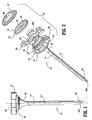
- Access device 10 generally includes housing 12 and elongate member 14 extending from the housing 12. Housing 12 and elongate member 14 define a longitudinal axis "a" which extends through and along the length of the device 10.
- housing 12 includes several components, which, when assembled, define a structure advantageously dimensioned to be held by the surgeon. These components include base 16, hub 18, seal 20 and cover 22.
- Base 16 defines an outer wall 24 having a plurality of spaced recesses 26 therein. Recesses 26 are generally rectangular in configuration as shown.
- the interior of base 16 has transverse ledge 28 upon which hub 18 rests and locking shelf 30 adjacent the proximal end of the base 16.
- Base 16 defines a distal tapered portion 32 which tapers inwardly relative to the longitudinal axis "a".
- tapered portion 32 incorporates a pair of intersecting surfaces 32a, 32b and a transverse shelf 32c. Tapered portion 32 functions in securing elongate member 14 to base 16 as will be discussed.
- Hub 18 of housing 12 includes disc-shaped portion 34 and annular wall 36 extending distally from the disc-shaped portion 34.
- Disc-shaped portion 34 has a plurality of vertical locks 38 extending upwardly from the disc-shaped portion 34.
- Vertical locks 38 are received within correspondingly positioned and dimensioned recesses 26 of base 16 in the assembled condition of housing 12.
- Vertical locks 38 each have an internal locking shelf 38a, which in combination with shelves 30 of the base 16 defines a continuous locking shelf when hub 18 is assembled within the base 16.
- Annular wall 36 of hub 18 is generally continuous and defines a diameter which is less than the effective internal diameter of base 16, and/or the effective diameter of the proximal end of elongate member 14.
- Annular wall 36 is received within base 16 and elongate member 14 upon assembly of the device 10.
- Hub 18 further includes a resilient seal or o-ring 40 which is accommodated within groove 42 disposed on the underside of the hub 18. O-ring 40 is adapted to form a gas-tight seal between hub 18 and base
- seal 20 includes an outer circumferential wall 44 and an inner seal portion 46 extending radially inwardly relative to the longitudinal axis "a".
- Inner seal portion 46 defines central aperture 48 which is dimensioned for passage of an object, e.g., a surgical instrument, guide wire, catheter or the hand of a surgeon.
- Seal 20 may be fabricated from any elastomeric material suitable for its intended purpose. A friction resisting coating may be applied to seal 20.
- Other valve types are also contemplated including zero-closure valves, slit valves, septum valves, double-slit valves, inflatable bladders, foam or gel valve arrangements, etc.
- Cover 22 has a general annular shape as shown defining a central opening 50 for permitting passage of the object.
- Cover 22 includes circumferential recess 52 on its underside or distal end face which accommodates outer circumferential wall 44 of seal 20.
- the peripheral area of cover 22 defines a ledge or shelf 54 which, in the assembled condition, engages locking shelf 30 of base 16 and/or locking shelf 38a of vertical locks 38 of hub 18 in snap relation therewith to thereby secure the remaining components of housing 12 within the base 16.
- Other mechanical arrangements for securing cover 22 to base 16 are also envisioned including, e.g., a screw thread arrangement, bayonet coupling, etc.
- housing 12 may be fabricated from any suitable generally rigid material (notwithstanding seal) including stainless steel, titanium or a rigid polymeric material.
- the components of housing 12 may be fabricated from any suitable medical grade material.
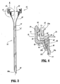
- Elongate member 14 defines a general tubular shape having proximal end 56 and distal end 58.
- Proximal end 56 is flared radially outwardly in a proximal direction and secured to housing 12.
- Distal end 58 includes an inclined surface 58a obliquely arranged relative to the longitudinal axis. This surface 58a facilitates passage of elongate member 14 through the tissue.
- Tubular elongate member 14 may be fabricated from any material which is capable of receiving the assembly of a cannula, dilator, or surgical instrument and capable of radial expansion of the elongate member 14. The materials are desirably medical grade materials including polymers and metals.
- elongate member 14 includes a braided material of inelastic filaments covered by an elastomeric membrane of, e.g., urethane, or any elastomeric material or as generally disclosed in commonly assigned U.S. Patent Nos. 5,431,676 and 6,245,052, the contents of each being incorporated herein by reference. It is also envisioned that a polyethylene sheath may be assembled over elongate member 14.
- the elongate member may comprise an elastomeric member or members without the braided material.
- Embodiments may include a material incorporating filaments, where the filaments may be elastic, inelastic, monofilaments, multifilaments, braided, woven, knitted or non-woven materials.
- the elongate member may comprise a braided, woven, knitted or non-woven material with or without an elastomeric membrane.
- elongate member 14 has a mounting element or ring 60 which is anchored within elongate member 14 adjacent proximal end 56.
- Mounting ring 60 is preferably retained within the proximal end 56 of elongate member 14 through a frictional arrangement or relationship created between the proximal end 56 of elongate member 14 and the mounting ring 60 as will be further discussed hereinbelow.
- Mounting ring 60 assists in securing elongate member 14 to housing 12.
- elongate member 14 is preferably a tubular braid.
- Tubular braids suitable for use as an access device are commercially available from, e.g., textile manufacturers, and, in particular, textile manufacturers specializing in medical devices.
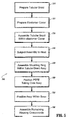
- Tubular braid is preferably cut to a desired length as dictated by the desired surgical objective for which device 10 will be used, illustrated as (STEP 210).
- an elastomer cover 13 preferably, a urethane cover is provided and cut to the desired length to correspond to the length of the tubular braid (STEP 220).
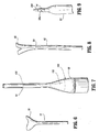
- FIG. 6 depicts a preferred arrangement of urethane cover 13.
- the urethane cover 13 preferably has a flared proximal portion 15 to define an inner diameter which increases toward the proximal end of the urethane cover 13. Such flaring of the end of urethane cover 13 may be effectuated by conventional extrusion processes used in forming the urethane cover 13.
- the thickness of the material of the elastomer cover including the flared portion 15 is constant throughout its length.
- the tubular braid 17 is positioned within the urethane cover (STEP 230) to assemble the unit.
- the assembly is subjected to a heating process (STEP 240) by positioning the assembly within an oven.
- pressure is applied by applying a vacuum, using a press or mold, so as to press the heated cover 13 into the braid.
- the elastomer e.g., urethane
- the elastomer becomes embedded within the fabric of the tubular braid to define a tubular braid/elastomer assembly.
- the assembly is thereafter cooled for a period of time.
- housing 12 and elongate member 14 are then assembled.
- a building or centering mandrel is utilized to assemble the components.
- a preferred mandrel is depicted in FIG. 7.
- This mandrel 100 includes a frusto-conical head 102 and a general rod-shaped element 104 extending from the head 102.
- mounting ring 60 is placed onto the mandrel 100.
- the elongate member 14 (comprising the tubular braid/elastomer assembly) is then slid over the mandrel 100 to a position where mounting ring 60 is received within the flared proximal end of the assembly as depicted in FIG. 7.
- proximal end of the elongate member may stretch to an expanded position to receive mounting ring 60.
- mounting ring 60 is preferably frictionally secured within the assembly 14 adjacent the proximal end.
- the elongate member 14 is then ground or cut at the distal end to the oblique surface 58a depicted in FIG. 1.
- FIG. 8 depicts the preferred tubing.
- the proximal end 66 of the tubing 62 may be partially separated or weakened to facilitate its detachment.
- the PTFE tubing 62 may be scored along a score line 64 to facilitate detachment during use.
- the tubing 62 may be secured to the tubular braid/elastomer assembly adjacent its proximal end or mounting ring 60 with an adhesive or glue.
- the tubing 62 extends beyond the oblique surface 58a, as shown in FIG. 9.
- FIG. 9 depicts the distal end of elongate member 14, with a needle 200 extending out of elongate member 14.
- the tubing 62 provides smooth transition from needle 200 and the oblique surface 58a.
- the needle 200 may be provided with the apparatus 10 as part of a kit or system for use during the surgical procedure.
- assembly is continued by positioning the elongate member 14 within base 16 of housing 12 such that mounting ring 60 is positioned within the interior of the base 16 (STEP 270).
- the tubular braid, cover 13, and tubing 62 is desirably folded over the ring 60, so that the elongate member 14 is captured between more than two surfaces of the housing, as shown in FIG. 4.
- Mounting ring 60 preferably causes tapered portion 32 of base 16 to deflect radially outwardly whereby, subsequent to positioning within the base 16, the mounting ring 60 engages transverse shelf 32c of the base 16.
- the assembly of housing 12 is continued (STEP 280). Seal 40 is placed in base 16 and hub 18 is assembled within base 16.
- annular wall 36 of hub 18 is received within mounting ring 60 and vertical locks 38 are received within recesses 26 of base 16. Thereafter, seal 18 is positioned within base 16, over the hub 18. Assembly is continued by mounting cover 22 to base 16 whereby shelf 54 of the cover 22 engages locking shelf 30 of base 16 to secure the components together. Outer circumferential wall 44 of seal 18 is accommodated within circumferential recess 52 of cover 22. Cover 22 secures the remaining components within base 16. It is envisioned that in the assembled condition mounting ring 60 may be pressed against the proximal end of elongate member 14 to compress the member 14 against tapered portion 32 of base 16. In addition, mounting ring 60 is prevented from release from base 16 by engagement with internal shelf 32c of the base 16. The elongate member 14 is mechanically secured in the housing 12, by being captured between the base 16 and hub 18.
- device 10 is percutaneously introduced to access a target site beneath the patient's skin.
- a needle or trocar 200 positioned in the device 10 to facilitate entry through the surgical site as discussed in connection with FIG. 9.
- oblique end 58a of elongate member 14 facilitates passage of access device 10 within the tissue.
- the needle or trocar is thereafter withdrawn leaving access device 10 within the tissue.
- a pneumoneedle is used for entry through the patient's skin and underlying layers and then used to introduce insufflation gas, in the case of laparoscopic surgery.
- a cannula 300 is then introduced within the inner lumen of the expandable elongate member 14 to expand the tubular braid/elastomer assembly to a desired internal diameter.
- the expansion of the elongate member 14 breaks the PTFE tubing 62.
- cannula 300 includes cannula housing 302 and a cannula sleeve 304 extending from the housing.
- Cannula sleeve 304 has an external threaded portion 306. The diameter of cannula sleeve 304 is greater than the internal diameter of elongate member 14.
- Cannula 300 is preferably rotated whereby the threaded portion 306 advances the cannula sleeve 304 within elongate member 14 of access device.
- the housing 12 desirably includes a flange for engaging the threaded portion 306.
- adjacent threads of threaded portion 306 engage surfaces 22a of cover 22 and surfaces 18a of hub 18 to advance cannula 300 upon rotation of the cannula 300, i.e., surfaces 18a, 22a function as an internal thread structure which is engaged by threaded portion 306 to advance the cannula 300.
- elongate member 14 expands to a second enlarged diameter shown in FIG. 11.
- the threaded portion enables the advancement of cannula 300 while minimizing the force directed in the distal direction.
- the threaded portion 306 may additionally be arranged for engaging the tissue.
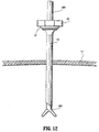
- elongate member 14 may be expanded with a dilator (not shown). It is also envisioned that the cannula sleeve 304 may be devoid of threads. Surgical instruments, scopes, etc. 400 may be introduced through the cannula to perform the desired procedure as shown in FIG. 12. After the procedure is finished, the cannula 300 is removed which causes tubular braid/elastomer assembly to collapse for subsequent removal. Optionally, other different diameter dilators or cannulas may be advanced within device 10 as desired.
- the base has a flange arranged for deflecting to receive the mounting ring 60, in a snap-fit manner so as to fixedly retain the ring 60.
- the ring depicted in the figures is round, the ring may have polygonal or oval shapes. Therefore, the above description should not be construed as limiting, but merely as exemplifications of preferred embodiments. Those skilled in the art will envision other modifications within the scope and spirit of the claims appended hereto.
Landscapes
- Health & Medical Sciences (AREA)
- Surgery (AREA)
- Life Sciences & Earth Sciences (AREA)
- Medical Informatics (AREA)
- Nuclear Medicine, Radiotherapy & Molecular Imaging (AREA)
- Engineering & Computer Science (AREA)
- Biomedical Technology (AREA)
- Heart & Thoracic Surgery (AREA)
- Pathology (AREA)
- Molecular Biology (AREA)
- Animal Behavior & Ethology (AREA)
- General Health & Medical Sciences (AREA)
- Public Health (AREA)
- Veterinary Medicine (AREA)
- Surgical Instruments (AREA)
- Endoscopes (AREA)
Applications Claiming Priority (2)
| Application Number | Priority Date | Filing Date | Title |
|---|---|---|---|
| US51254803P | 2003-10-17 | 2003-10-17 | |
| US512548P | 2003-10-17 |
Publications (2)
| Publication Number | Publication Date |
|---|---|
| EP1523948A1 true EP1523948A1 (fr) | 2005-04-20 |
| EP1523948B1 EP1523948B1 (fr) | 2009-12-02 |
Family
ID=34375603
Family Applications (1)
| Application Number | Title | Priority Date | Filing Date |
|---|---|---|---|
| EP04024600A Expired - Lifetime EP1523948B1 (fr) | 2003-10-17 | 2004-10-15 | Dispositif d'accès chirurgical et son procédé de fabrication |
Country Status (7)
| Country | Link |
|---|---|
| US (2) | US7892170B2 (fr) |
| EP (1) | EP1523948B1 (fr) |
| JP (2) | JP5031982B2 (fr) |
| AU (3) | AU2004220757B2 (fr) |
| CA (2) | CA2484906C (fr) |
| DE (1) | DE602004024362D1 (fr) |
| ES (1) | ES2336324T3 (fr) |
Cited By (5)
| Publication number | Priority date | Publication date | Assignee | Title |
|---|---|---|---|---|
| EP1839600A1 (fr) * | 2006-03-30 | 2007-10-03 | Levitronix LLC | Tube de guidage expansible |
| EP2044897A1 (fr) * | 2007-10-05 | 2009-04-08 | Tyco Healthcare Group LP | Extension de l'ancrage de joint pour une intervention à incision unique |
| CN101966099A (zh) * | 2010-11-03 | 2011-02-09 | 上海理工大学 | 简易型单孔手术操作平台 |
| US8591538B2 (en) | 2006-03-30 | 2013-11-26 | Thoratec Llc | Self-expanding cannula and a method for applying and positioning a self-expanding cannula |
| EP2853209B1 (fr) * | 2013-09-27 | 2020-08-26 | DePuy Synthes Products, Inc. | Canule flexible et obturateur |
Families Citing this family (16)
| Publication number | Priority date | Publication date | Assignee | Title |
|---|---|---|---|---|
| US20040260244A1 (en) * | 2001-08-31 | 2004-12-23 | Piechowicz Michael E. | Seals for trocars |
| US20110028795A1 (en) * | 2009-07-29 | 2011-02-03 | Tyco Healthcare Group Lp | Surgical portal device including textured surface |
| US8926508B2 (en) | 2009-12-17 | 2015-01-06 | Covidien Lp | Access assembly with dual anchor and seal capabilities |
| US9022923B2 (en) * | 2010-11-16 | 2015-05-05 | Ethicon Endo-Surgery, Inc. | Implantable injection port with tissue in-growth promoter |
| WO2012082754A1 (fr) * | 2010-12-13 | 2012-06-21 | I-Tech Development Company | Outil chirurgical auto-obturant |
| EP2695581B1 (fr) | 2012-08-07 | 2019-03-13 | Critical Innovations, LLC | Dispositif permettant de documenter et de traiter simultanément un pneumothorax et/ou hémothorax sous pression |
| US9115945B2 (en) * | 2012-11-08 | 2015-08-25 | Otis Products, Inc. | Apparatus and method for cleaning the barrel of a firearm |
| US11039735B2 (en) | 2013-03-13 | 2021-06-22 | Spiway Llc | Surgical tissue protection sheath |
| US10986984B2 (en) | 2013-03-13 | 2021-04-27 | Spiway Llc | Surgical tissue protection sheath |
| US10046147B2 (en) | 2013-12-26 | 2018-08-14 | Critical Innovations, LLC | Percutaneous access pathway system and method |
| CA3203993A1 (fr) * | 2014-08-15 | 2016-02-18 | Applied Medical Resources Corporation | Systeme de chirurgie d'orifice naturel |
| WO2018035430A1 (fr) * | 2016-08-19 | 2018-02-22 | Spiway Llc | Gaine de protection de tissu chirurgical |
| US10814119B2 (en) | 2017-09-22 | 2020-10-27 | Critical Innovations, LLC | Percutaneous access pathway system |
| CA3082525C (fr) | 2017-12-13 | 2022-10-18 | Conmed Corporation | Protection portale d'acces a la hanche |
| US11583313B1 (en) | 2018-12-06 | 2023-02-21 | Spiway Llc | Surgical access sheath and methods of use |
| US11944345B1 (en) * | 2022-10-24 | 2024-04-02 | King Faisal University | Radially expanding trocar for laparoscopic cholecystectomy |
Citations (6)
| Publication number | Priority date | Publication date | Assignee | Title |
|---|---|---|---|---|
| US5139511A (en) * | 1990-02-14 | 1992-08-18 | Gill Steven S | Expansible cannula |
| US5320611A (en) * | 1993-02-04 | 1994-06-14 | Peter M. Bonutti | Expandable cannula having longitudinal wire and method of use |
| US5814058A (en) * | 1993-03-05 | 1998-09-29 | Innerdyne, Inc. | Method and apparatus employing conformable sleeve for providing percutaneous access |
| US6090072A (en) * | 1992-10-15 | 2000-07-18 | Scimed Life Systems, Inc. | Expandable introducer sheath |
| US6162236A (en) * | 1994-07-11 | 2000-12-19 | Terumo Kabushiki Kaisha | Trocar needle and expandable trocar tube |
| WO2003011154A2 (fr) * | 2001-08-01 | 2003-02-13 | Tyco Healthcare Group Lp | Appareil et procede permettant de pratiquer un acces percutane vers un site chirurgical cible et d'envoyer un medicament vers ce site |
Family Cites Families (62)
| Publication number | Priority date | Publication date | Assignee | Title |
|---|---|---|---|---|
| US1361758A (en) * | 1919-04-17 | 1920-12-07 | Arno A Ewald | Hose-coupling |
| SE428088B (sv) * | 1981-10-14 | 1983-06-06 | Meteve Ab | Troakar |
| SE445884B (sv) | 1982-04-30 | 1986-07-28 | Medinvent Sa | Anordning for implantation av en rorformig protes |
| GB8513702D0 (en) | 1985-05-30 | 1985-07-03 | Gill S S | Expansible trocar |
| JPS63114616A (ja) * | 1986-10-31 | 1988-05-19 | Mazda Motor Corp | 射出成形金型 |
| JPH0432084Y2 (fr) * | 1987-01-20 | 1992-07-31 | ||
| US4772266A (en) | 1987-05-04 | 1988-09-20 | Catheter Technology Corp. | Catheter dilator/sheath assembly and method |
| US4921479A (en) | 1987-10-02 | 1990-05-01 | Joseph Grayzel | Catheter sheath with longitudinal seam |
| US4931042A (en) * | 1987-10-26 | 1990-06-05 | Endotherapeutics | Trocar assembly with improved latch |
| US5499975A (en) | 1989-01-31 | 1996-03-19 | Cook Incorporated | Smooth transitioned dilator-sheath assembly and method |
| US5234425A (en) | 1989-03-03 | 1993-08-10 | Thomas J. Fogarty | Variable diameter sheath method and apparatus for use in body passages |
| US5066285A (en) | 1990-01-26 | 1991-11-19 | Cordis Corporation | Catheter introducer sheath made of expanded polytetrafluoroethylene |
| US5201756A (en) | 1990-06-20 | 1993-04-13 | Danforth Biomedical, Inc. | Radially-expandable tubular elements for use in the construction of medical devices |
| US5085645A (en) * | 1990-08-15 | 1992-02-04 | Becton, Dickinson And Company | Apparatus and method for a catheter adapter with valve |
| US5178133A (en) * | 1991-03-26 | 1993-01-12 | Pena Louis T | Laparoscopic retractor and sheath |
| US5688246A (en) | 1991-04-19 | 1997-11-18 | Biotime, Inc. | Microcannula |
| US5158545A (en) | 1991-05-02 | 1992-10-27 | Brigham And Women's Hospital | Diameter expansion cannula |
| US5183464A (en) | 1991-05-17 | 1993-02-02 | Interventional Thermodynamics, Inc. | Radially expandable dilator |
| DE4129781C2 (de) * | 1991-09-07 | 1996-09-05 | Haindl Hans | Schlauchkupplung, insbesondere zum Anschluß eines Schlauchkatheters an einen Port eines Portkathetersystems |
| US5256150A (en) | 1991-12-13 | 1993-10-26 | Endovascular Technologies, Inc. | Large-diameter expandable sheath and method |
| JP2525724B2 (ja) | 1992-04-09 | 1996-08-21 | メドトロニック インコーポレーテッド | 機械的開放弁を有するリ―ド誘導針 |
| JP3126077B2 (ja) * | 1992-04-14 | 2001-01-22 | オリンパス光学工業株式会社 | トラカール |
| US5443484A (en) * | 1992-06-16 | 1995-08-22 | Loma Linda University Medical Center | Trocar and method for endoscopic surgery |
| ATE149325T1 (de) | 1992-10-12 | 1997-03-15 | Schneider Europ Ag | Katheter mit einer gefässstütze |
| US5250033A (en) | 1992-10-28 | 1993-10-05 | Interventional Thermodynamics, Inc. | Peel-away introducer sheath having proximal fitting |
| US5423849A (en) | 1993-01-15 | 1995-06-13 | Target Therapeutics, Inc. | Vasoocclusion device containing radiopaque fibers |
| US6338730B1 (en) | 1993-02-04 | 2002-01-15 | Peter M. Bonutti | Method of using expandable cannula |
| US5961499A (en) | 1993-02-04 | 1999-10-05 | Peter M. Bonutti | Expandable cannula |
| US5814073A (en) | 1996-12-13 | 1998-09-29 | Bonutti; Peter M. | Method and apparatus for positioning a suture anchor |
| US5431676A (en) | 1993-03-05 | 1995-07-11 | Innerdyne Medical, Inc. | Trocar system having expandable port |
| JP3310721B2 (ja) * | 1993-06-03 | 2002-08-05 | テルモ株式会社 | 軟性トロカール管 |
| US5630822A (en) | 1993-07-02 | 1997-05-20 | General Surgical Innovations, Inc | Laparoscopic tissue removal device |
| US5395341A (en) | 1994-03-21 | 1995-03-07 | Cordis Corporation | One piece vessel dilator/catheter sheath introducer |
| US5454790A (en) | 1994-05-09 | 1995-10-03 | Innerdyne, Inc. | Method and apparatus for catheterization access |
| JP3759178B2 (ja) * | 1994-07-11 | 2006-03-22 | テルモ株式会社 | トロカール管及びそれを備えたトロカール |
| US5460170A (en) * | 1994-08-23 | 1995-10-24 | Hammerslag; Julius G. | Adjustable surgical retractor |
| US5660186A (en) * | 1995-06-07 | 1997-08-26 | Marshfield Clinic | Spiral biopsy stylet |
| US5746720A (en) * | 1995-10-18 | 1998-05-05 | Stouder, Jr.; Albert E. | Method and apparatus for insertion of a cannula and trocar |
| US5782807A (en) | 1995-10-20 | 1998-07-21 | Tfx Medical Incorporated | Releasably locking introducer devices |
| US6228052B1 (en) | 1996-02-29 | 2001-05-08 | Medtronic Inc. | Dilator for introducer system having injection port |
| US5827319A (en) * | 1996-05-20 | 1998-10-27 | Innerdyne, Inc. | Radially expandable access system having disposable and reusable components |
| US5827227A (en) | 1996-07-17 | 1998-10-27 | Delago; Augustin J. | Catheter having a radially adjustable sheath |
| US5944691A (en) | 1996-11-04 | 1999-08-31 | Cordis Corporation | Catheter having an expandable shaft |
| US5836913A (en) | 1997-05-02 | 1998-11-17 | Innerdyne, Inc. | Device and method for accessing a body cavity |
| WO1998052631A1 (fr) * | 1997-05-20 | 1998-11-26 | Baxter International, Inc. | Connecteur sans aiguille |
| US5984957A (en) | 1997-08-12 | 1999-11-16 | Schneider (Usa) Inc | Radially expanded prostheses with axial diameter control |
| US6019776A (en) * | 1997-10-14 | 2000-02-01 | Parallax Medical, Inc. | Precision depth guided instruments for use in vertebroplasty |
| US6387095B1 (en) | 1998-02-09 | 2002-05-14 | Loren R. Kennett | Surgical device comprising a radially expandable non-conductive sheath |
| US6245052B1 (en) | 1998-07-08 | 2001-06-12 | Innerdyne, Inc. | Methods, systems, and kits for implanting articles |
| FR2781380B1 (fr) * | 1998-07-27 | 2000-09-15 | Braun Celsa Sa | Bague pour lier un tube souple deformable et une tige resistante a l'ecrasement, et ensemble medical muni d'une telle bague |
| US5916145A (en) | 1998-08-07 | 1999-06-29 | Scimed Life Systems, Inc. | Device and method of using a surgical assembly with mesh sheath |
| US5957902A (en) | 1998-09-28 | 1999-09-28 | Teves; Leonides Y. | Surgical tool for enlarging puncture opening made by trocar |
| US6159179A (en) | 1999-03-12 | 2000-12-12 | Simonson; Robert E. | Cannula and sizing and insertion method |
| US6607547B1 (en) | 1999-08-25 | 2003-08-19 | Origin Medsystems, Inc. | Longitudinal dilator and method |
| US6358238B1 (en) | 1999-09-02 | 2002-03-19 | Scimed Life Systems, Inc. | Expandable micro-catheter |
| US6589262B1 (en) | 2000-03-31 | 2003-07-08 | Medamicus, Inc. | Locking catheter introducing system |
| US6543817B1 (en) * | 2000-07-31 | 2003-04-08 | Whitley Products, Inc. | Process for forming radially upset tube flange and tube connector assembly formed thereby |
| US6547803B2 (en) | 2001-09-20 | 2003-04-15 | The Regents Of The University Of California | Microfabricated surgical device for interventional procedures |
| US20030216770A1 (en) * | 2002-02-21 | 2003-11-20 | Persidsky Maxim D. | Apparatus and method for making a percutaneous access port of variable size |
| US6723044B2 (en) * | 2002-03-14 | 2004-04-20 | Apple Medical Corporation | Abdominal retractor |
| US6991603B2 (en) * | 2002-05-17 | 2006-01-31 | Optim, Inc. | Insertion tube device |
| JP2007525242A (ja) * | 2003-04-25 | 2007-09-06 | タイコ ヘルスケア グループ エルピー | 外科手術用アクセス装置 |
-
2004
- 2004-10-15 ES ES04024600T patent/ES2336324T3/es not_active Expired - Lifetime
- 2004-10-15 CA CA2484906A patent/CA2484906C/fr not_active Expired - Fee Related
- 2004-10-15 CA CA2762928A patent/CA2762928C/fr not_active Expired - Fee Related
- 2004-10-15 DE DE602004024362T patent/DE602004024362D1/de not_active Expired - Lifetime
- 2004-10-15 US US10/967,056 patent/US7892170B2/en active Active
- 2004-10-15 AU AU2004220757A patent/AU2004220757B2/en not_active Ceased
- 2004-10-15 EP EP04024600A patent/EP1523948B1/fr not_active Expired - Lifetime
- 2004-10-18 JP JP2004303586A patent/JP5031982B2/ja not_active Expired - Fee Related
-
2009
- 2009-11-23 AU AU2009238384A patent/AU2009238384B2/en not_active Ceased
-
2010
- 2010-08-18 JP JP2010183512A patent/JP5139483B2/ja not_active Expired - Fee Related
- 2010-09-16 AU AU2010224292A patent/AU2010224292B2/en not_active Ceased
-
2011
- 2011-01-19 US US13/008,932 patent/US8708898B2/en not_active Expired - Lifetime
Patent Citations (6)
| Publication number | Priority date | Publication date | Assignee | Title |
|---|---|---|---|---|
| US5139511A (en) * | 1990-02-14 | 1992-08-18 | Gill Steven S | Expansible cannula |
| US6090072A (en) * | 1992-10-15 | 2000-07-18 | Scimed Life Systems, Inc. | Expandable introducer sheath |
| US5320611A (en) * | 1993-02-04 | 1994-06-14 | Peter M. Bonutti | Expandable cannula having longitudinal wire and method of use |
| US5814058A (en) * | 1993-03-05 | 1998-09-29 | Innerdyne, Inc. | Method and apparatus employing conformable sleeve for providing percutaneous access |
| US6162236A (en) * | 1994-07-11 | 2000-12-19 | Terumo Kabushiki Kaisha | Trocar needle and expandable trocar tube |
| WO2003011154A2 (fr) * | 2001-08-01 | 2003-02-13 | Tyco Healthcare Group Lp | Appareil et procede permettant de pratiquer un acces percutane vers un site chirurgical cible et d'envoyer un medicament vers ce site |
Cited By (8)
| Publication number | Priority date | Publication date | Assignee | Title |
|---|---|---|---|---|
| EP1839600A1 (fr) * | 2006-03-30 | 2007-10-03 | Levitronix LLC | Tube de guidage expansible |
| US8591539B2 (en) | 2006-03-30 | 2013-11-26 | Thoratec Llc | Expandable conduit-guide and a method for applying and positioning an expandable conduit-guide |
| US8591538B2 (en) | 2006-03-30 | 2013-11-26 | Thoratec Llc | Self-expanding cannula and a method for applying and positioning a self-expanding cannula |
| EP2044897A1 (fr) * | 2007-10-05 | 2009-04-08 | Tyco Healthcare Group LP | Extension de l'ancrage de joint pour une intervention à incision unique |
| CN101401720B (zh) * | 2007-10-05 | 2012-11-07 | Tyco医疗健康集团 | 用于单切口手术的张开密封锚定装置 |
| US9474518B2 (en) | 2007-10-05 | 2016-10-25 | Covidien Lp | Expanding seal anchor for single incision surgery |
| CN101966099A (zh) * | 2010-11-03 | 2011-02-09 | 上海理工大学 | 简易型单孔手术操作平台 |
| EP2853209B1 (fr) * | 2013-09-27 | 2020-08-26 | DePuy Synthes Products, Inc. | Canule flexible et obturateur |
Also Published As
| Publication number | Publication date |
|---|---|
| DE602004024362D1 (de) | 2010-01-14 |
| EP1523948B1 (fr) | 2009-12-02 |
| ES2336324T3 (es) | 2010-04-12 |
| AU2010224292B2 (en) | 2012-11-15 |
| CA2762928C (fr) | 2014-09-16 |
| CA2762928A1 (fr) | 2005-04-17 |
| JP5031982B2 (ja) | 2012-09-26 |
| AU2009238384A1 (en) | 2009-12-10 |
| CA2484906A1 (fr) | 2005-04-17 |
| AU2004220757A1 (en) | 2005-05-05 |
| JP5139483B2 (ja) | 2013-02-06 |
| US7892170B2 (en) | 2011-02-22 |
| JP2005118581A (ja) | 2005-05-12 |
| AU2004220757B2 (en) | 2010-06-17 |
| AU2010224292A1 (en) | 2010-10-14 |
| US20110174425A1 (en) | 2011-07-21 |
| US8708898B2 (en) | 2014-04-29 |
| JP2011011065A (ja) | 2011-01-20 |
| CA2484906C (fr) | 2012-12-04 |
| AU2009238384B2 (en) | 2011-06-23 |
| US20050192608A1 (en) | 2005-09-01 |
Similar Documents
| Publication | Publication Date | Title |
|---|---|---|
| US8708898B2 (en) | Surgical access device and manufacture thereof | |
| US5431676A (en) | Trocar system having expandable port | |
| EP1702575B1 (fr) | Système d'accès expansible radialement avec un joint de trocart | |
| US20040172041A1 (en) | Sheath introduction apparatus and method | |
| US10675114B2 (en) | Access sheath for brain surgery | |
| CA2582323C (fr) | Systeme pour chirurgie laparoscopique |
Legal Events
| Date | Code | Title | Description |
|---|---|---|---|
| PUAI | Public reference made under article 153(3) epc to a published international application that has entered the european phase |
Free format text: ORIGINAL CODE: 0009012 |
|
| AK | Designated contracting states |
Kind code of ref document: A1 Designated state(s): AT BE BG CH CY CZ DE DK EE ES FI FR GB GR HU IE IT LI LU MC NL PL PT RO SE SI SK TR |
|
| AX | Request for extension of the european patent |
Extension state: AL HR LT LV MK |
|
| 17P | Request for examination filed |
Effective date: 20050921 |
|
| AKX | Designation fees paid |
Designated state(s): DE ES FR GB IE IT |
|
| 17Q | First examination report despatched |
Effective date: 20070105 |
|
| GRAP | Despatch of communication of intention to grant a patent |
Free format text: ORIGINAL CODE: EPIDOSNIGR1 |
|
| GRAS | Grant fee paid |
Free format text: ORIGINAL CODE: EPIDOSNIGR3 |
|
| GRAA | (expected) grant |
Free format text: ORIGINAL CODE: 0009210 |
|
| AK | Designated contracting states |
Kind code of ref document: B1 Designated state(s): DE ES FR GB IE IT |
|
| REG | Reference to a national code |
Ref country code: GB Ref legal event code: FG4D |
|
| REG | Reference to a national code |
Ref country code: IE Ref legal event code: FG4D |
|
| REF | Corresponds to: |
Ref document number: 602004024362 Country of ref document: DE Date of ref document: 20100114 Kind code of ref document: P |
|
| REG | Reference to a national code |
Ref country code: ES Ref legal event code: FG2A Ref document number: 2336324 Country of ref document: ES Kind code of ref document: T3 |
|
| PLBE | No opposition filed within time limit |
Free format text: ORIGINAL CODE: 0009261 |
|
| STAA | Information on the status of an ep patent application or granted ep patent |
Free format text: STATUS: NO OPPOSITION FILED WITHIN TIME LIMIT |
|
| 26N | No opposition filed |
Effective date: 20100903 |
|
| PGFP | Annual fee paid to national office [announced via postgrant information from national office to epo] |
Ref country code: ES Payment date: 20121026 Year of fee payment: 9 Ref country code: IT Payment date: 20121023 Year of fee payment: 9 |
|
| PG25 | Lapsed in a contracting state [announced via postgrant information from national office to epo] |
Ref country code: IT Free format text: LAPSE BECAUSE OF NON-PAYMENT OF DUE FEES Effective date: 20131015 |
|
| REG | Reference to a national code |
Ref country code: ES Ref legal event code: FD2A Effective date: 20150529 |
|
| PG25 | Lapsed in a contracting state [announced via postgrant information from national office to epo] |
Ref country code: ES Free format text: LAPSE BECAUSE OF NON-PAYMENT OF DUE FEES Effective date: 20131016 |
|
| REG | Reference to a national code |
Ref country code: FR Ref legal event code: PLFP Year of fee payment: 13 |
|
| REG | Reference to a national code |
Ref country code: FR Ref legal event code: PLFP Year of fee payment: 14 |
|
| REG | Reference to a national code |
Ref country code: FR Ref legal event code: PLFP Year of fee payment: 15 |
|
| PGFP | Annual fee paid to national office [announced via postgrant information from national office to epo] |
Ref country code: IE Payment date: 20230921 Year of fee payment: 20 Ref country code: GB Payment date: 20230920 Year of fee payment: 20 |
|
| PGFP | Annual fee paid to national office [announced via postgrant information from national office to epo] |
Ref country code: FR Payment date: 20230920 Year of fee payment: 20 |
|
| PGFP | Annual fee paid to national office [announced via postgrant information from national office to epo] |
Ref country code: DE Payment date: 20230920 Year of fee payment: 20 |
|
| REG | Reference to a national code |
Ref country code: DE Ref legal event code: R071 Ref document number: 602004024362 Country of ref document: DE |
|
| REG | Reference to a national code |
Ref country code: GB Ref legal event code: PE20 Expiry date: 20241014 |
|
| REG | Reference to a national code |
Ref country code: IE Ref legal event code: MK9A |
|
| PG25 | Lapsed in a contracting state [announced via postgrant information from national office to epo] |
Ref country code: GB Free format text: LAPSE BECAUSE OF EXPIRATION OF PROTECTION Effective date: 20241014 |
|
| PG25 | Lapsed in a contracting state [announced via postgrant information from national office to epo] |
Ref country code: IE Free format text: LAPSE BECAUSE OF EXPIRATION OF PROTECTION Effective date: 20241015 |
|
| PG25 | Lapsed in a contracting state [announced via postgrant information from national office to epo] |
Ref country code: IE Free format text: LAPSE BECAUSE OF EXPIRATION OF PROTECTION Effective date: 20241015 Ref country code: GB Free format text: LAPSE BECAUSE OF EXPIRATION OF PROTECTION Effective date: 20241014 |