EP1523928A2 - A dish-washing machine with versatility of position of dishrack - Google Patents
A dish-washing machine with versatility of position of dishrack Download PDFInfo
- Publication number
- EP1523928A2 EP1523928A2 EP04105103A EP04105103A EP1523928A2 EP 1523928 A2 EP1523928 A2 EP 1523928A2 EP 04105103 A EP04105103 A EP 04105103A EP 04105103 A EP04105103 A EP 04105103A EP 1523928 A2 EP1523928 A2 EP 1523928A2
- Authority
- EP
- European Patent Office
- Prior art keywords
- dish
- washing machine
- washing
- station
- rinsing
- Prior art date
- Legal status (The legal status is an assumption and is not a legal conclusion. Google has not performed a legal analysis and makes no representation as to the accuracy of the status listed.)
- Granted
Links
Images
Classifications
-
- A—HUMAN NECESSITIES
- A47—FURNITURE; DOMESTIC ARTICLES OR APPLIANCES; COFFEE MILLS; SPICE MILLS; SUCTION CLEANERS IN GENERAL
- A47L—DOMESTIC WASHING OR CLEANING; SUCTION CLEANERS IN GENERAL
- A47L15/00—Washing or rinsing machines for crockery or tableware
- A47L15/42—Details
- A47L15/50—Racks ; Baskets
- A47L15/507—Arrangements for extracting racks, e.g. roller supports
-
- A—HUMAN NECESSITIES
- A47—FURNITURE; DOMESTIC ARTICLES OR APPLIANCES; COFFEE MILLS; SPICE MILLS; SUCTION CLEANERS IN GENERAL
- A47L—DOMESTIC WASHING OR CLEANING; SUCTION CLEANERS IN GENERAL
- A47L15/00—Washing or rinsing machines for crockery or tableware
- A47L15/24—Washing or rinsing machines for crockery or tableware with movement of the crockery baskets by conveyors
-
- A—HUMAN NECESSITIES
- A47—FURNITURE; DOMESTIC ARTICLES OR APPLIANCES; COFFEE MILLS; SPICE MILLS; SUCTION CLEANERS IN GENERAL
- A47L—DOMESTIC WASHING OR CLEANING; SUCTION CLEANERS IN GENERAL
- A47L15/00—Washing or rinsing machines for crockery or tableware
- A47L15/42—Details
- A47L15/50—Racks ; Baskets
- A47L15/504—Arrangements for changing the height of racks
-
- A—HUMAN NECESSITIES
- A47—FURNITURE; DOMESTIC ARTICLES OR APPLIANCES; COFFEE MILLS; SPICE MILLS; SUCTION CLEANERS IN GENERAL
- A47L—DOMESTIC WASHING OR CLEANING; SUCTION CLEANERS IN GENERAL
- A47L19/00—Drying devices for crockery or table-ware, e.g. tea-cloths
- A47L19/04—Crockery baskets; Draining-racks
Definitions
- the present invention relates to a dish-washing machine with versatility of position.
- dish-washing machines used in establishments such as hotels and restaurants comprise at least one loading station, a washing station, a rinsing station, and an unloading station.
- the sequence of these stations and of their components is fixed and is established when the machine itself is made.
- dish-washing machine Such a constraint results in a limitation in the positioning the dish-washing machine.
- the dish-washing machines described above can be set only in certain positions, thus affecting the disposition of the premises that house them.
- the purpose of the present invention is to provide a dish-washing machine the technical characteristics of which will enable the drawbacks of the known art to be overcome in a simple and economically advantageous way.
- the subject of the present invention is a dish-washing machine comprising: at least one washing station, defined by one or more washing arms; a rinsing station, defined by one or more rinsing arms; and movement means, designed to displace a dish rack at least from the washing station to the rinsing station; said dish-washing machine being characterized in that it comprises attachment means for said rinsing arms positioned on both sides of said washing station, and in that said movement means are reversible.
- the dish-washing machine of the present invention affords the considerable advantage of reversing the direction in which the dish rack moves by displacing just the rinsing station with respect to the washing station, i.e., without modifying the position of the washing arms. In this way, it will be possible to set the dish-washing machine in the most convenient position for loading and unloading.
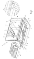
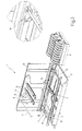
- the dish-washing machine 1 comprises: a supporting structure 2 for supporting the movement means 3; a washing station 4, defined by three washing arms 5, from which a water/detergent mixture is delivered; and a rinsing station 6, defined by two rinsing arms 7, from which the rinsing water is delivered.
- the dish-washing machine 1 further comprises a first attachment assembly 8 and a second attachment assembly 9 for attachment of the rinsing arms 7.
- the two assemblies 8 and 9 are arranged on opposite sides with respect to the washing station 4. In this way, it is possible to fix, as desired, the position of the rinsing station 6 with respect to the washing station 4.
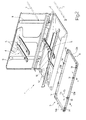
- the movement means 3 have the function of displacing a dish rack 10 from the washing station 4 to the rinsing station 6, and comprise a thrust carriage 11 and an actuation assembly 12, designed to move the carriage 11 according to a reciprocating translational motion.
- the thrust carriage 11 comprises a rectangular frame 13, a plurality of engagement teeth 14, hinged on two long sides 13a of the frame 13, and a handle element 15.
- the actuation assembly 12 comprises a pin 16, which engages the handle element 15 and moves along a circular path and is moved by an appropriate electric motor (known and not illustrated herein). As is known, the engagement of the pin 16 with the handle element 15 enables conversion of the circular motion of the pin 16 itself into the reciprocating translational motion of the thrust carriage 11.
- the engagement teeth 14 are hinged to the frame 13 in such a way that, only when the thrust carriage 11 is displaced in one direction, they remain in a vertical position so that they can exert the action of thrust on the rack 10.
- the handle element 15 can be fixed in a removable way indifferently to one or other of the two short sides 13b of the frame 13. In this way, it will be possible to set the correct direction of advance of the rack 10 according to where the rinsing station 6 has been positioned with respect to the washing station 4.
- the dish-washing machine of the present invention can set the rinsing station in two different positions with respect to the washing station, which remains fixed. From a comparison of the enlarged details of Figures 1 and 3, it may be noted how, by replacing the short side 13b, on which the handle element 15 is fixed, and rotating the frame 13 through 180°, it is possible to set the engagement teeth 14 in the correct direction.
- the dish-washing machine of the present invention enables freedom of displacement of the rinsing station, and hence the loading station, according to the disposition of the premises in which the dish-washing machine itself is to be set.
Landscapes
- Washing And Drying Of Tableware (AREA)
- Cleaning By Liquid Or Steam (AREA)
Abstract
Description
- Figure 1 is a perspective view of a dish-washing machine, with parts removed, according to a preferred embodiment of the present invention;
- Figure 2 is an exploded view of the portion of the dish-washing machine of Figure 1; and
- Figure 3 is a perspective view of the dish-washing machine of Figure 1 in a further configuration of operation thereof.
Claims (6)
- A dish-washing machine (1) comprising: at least one supporting structure (2); a washing station (4), defined by one or more washing arms (5); a rinsing station (6), defined by one or more rinsing arms (7); and movement means (3), designed to displace a dish rack (10) at least from the washing station (4) to the rinsing station (6); said dish-washing machine being characterized in that it comprises at least two attachment assemblies (8, 9) for attachment of said rinsing arms (7) positioned on opposite sides of said washing arms (5), and in that said movement means (3) are reversible.
- The dish-washing machine according to Claim 1, characterized in that said movement means (3) comprise a thrust carriage (11) orientable according to the direction of the thrust that it is desired to exert on said dish rack (10), and an actuation assembly (12) for actuation of said thrust means (11).
- The dish-washing machine according to Claim 2, characterized in that said actuation assembly (12) is fixedly set on said supporting structure (2).
- The dish-washing machine according to Claim 3, characterized in that said thrust carriage (11) comprises a removable element (15), which is engaged by said actuation means (12) and the position of which determines the direction of the action of thrust.
- The dish-washing machine according to Claim 4, characterized in that said thrust carriage (11) comprises a frame (13), a plurality of engagement teeth (14), hinged to said frame (13), and in that said removable element is a handle element (15), designed to be fixed in a removable way alternatively on at least two opposite sides (13b) of said frame (13).
- The dish-washing machine according to Claim 5, characterized in that said engagement teeth (14) are hinged on the two long sides (13a) of said frame (13), and in that said handle element (15) can be fixed indifferently on one or other of the two short sides (13b) of said frame (13).
Applications Claiming Priority (2)
| Application Number | Priority Date | Filing Date | Title |
|---|---|---|---|
| IT000610A ITBO20030610A1 (en) | 2003-10-17 | 2003-10-17 | DISHWASHER MACHINE WITH POSITION VERSATILITY. |
| ITBO20030610 | 2003-10-17 |
Publications (3)
| Publication Number | Publication Date |
|---|---|
| EP1523928A2 true EP1523928A2 (en) | 2005-04-20 |
| EP1523928A3 EP1523928A3 (en) | 2006-02-01 |
| EP1523928B1 EP1523928B1 (en) | 2009-09-09 |
Family
ID=34362399
Family Applications (1)
| Application Number | Title | Priority Date | Filing Date |
|---|---|---|---|
| EP04105103A Not-in-force EP1523928B1 (en) | 2003-10-17 | 2004-10-15 | A dish-washing machine with versatility of position of dishrack |
Country Status (11)
| Country | Link |
|---|---|
| US (1) | US7404410B2 (en) |
| EP (1) | EP1523928B1 (en) |
| JP (1) | JP2005118578A (en) |
| KR (1) | KR20050037359A (en) |
| CN (1) | CN100469302C (en) |
| AU (1) | AU2004218738B2 (en) |
| BR (1) | BRPI0404408A (en) |
| DE (1) | DE602004023041D1 (en) |
| IT (1) | ITBO20030610A1 (en) |
| MX (1) | MXPA04010236A (en) |
| NZ (1) | NZ535931A (en) |
Cited By (1)
| Publication number | Priority date | Publication date | Assignee | Title |
|---|---|---|---|---|
| WO2008014215A3 (en) * | 2006-07-26 | 2008-04-10 | Premark Feg Llc | Drive systems for conveyor-type warewashers |
Families Citing this family (2)
| Publication number | Priority date | Publication date | Assignee | Title |
|---|---|---|---|---|
| CN102821877B (en) * | 2009-12-17 | 2014-12-17 | 杰克逊Msc有限责任公司 | Warewashing system arm |
| US11344179B2 (en) | 2019-12-20 | 2022-05-31 | Whirlpool Corporation | Dish treating appliance with a dish rack and rail assembly |
Citations (4)
| Publication number | Priority date | Publication date | Assignee | Title |
|---|---|---|---|---|
| US2073521A (en) * | 1931-01-17 | 1937-03-09 | Hobart Mfg Co | Washing machine |
| US2974672A (en) * | 1956-07-06 | 1961-03-14 | Hobart Mfg Co | Washing machine |
| DE3235007A1 (en) * | 1982-09-22 | 1984-03-22 | Stierlen-Maquet Ag, 7550 Rastatt | Conveying device on a dish-washing installation |
| EP0917277A1 (en) * | 1997-11-18 | 1999-05-19 | MEIKO Maschinenbau GmbH & Co. | Motor drive |
Family Cites Families (6)
| Publication number | Priority date | Publication date | Assignee | Title |
|---|---|---|---|---|
| DE917277C (en) * | 1944-01-06 | 1954-08-30 | Zeiss Carl Fa | Methods and devices for comparing the outline shape of a profiled body with the desired shape of the outline |
| CN2101460U (en) * | 1991-04-28 | 1992-04-15 | 周洪 | Automatic washing machine for tableware |
| US5927616A (en) * | 1997-09-04 | 1999-07-27 | Premark Feg L.L.C. | Quick change rinse arm for warewasher |
| JP2002325714A (en) * | 2001-03-01 | 2002-11-12 | Sanyo Electric Co Ltd | Dishwasher |
| DE10163181A1 (en) * | 2001-12-21 | 2003-07-10 | Bsh Bosch Siemens Hausgeraete | Reversing device, in particular for a dishwasher |
| US6955179B2 (en) * | 2002-12-30 | 2005-10-18 | Meiko Maschinenbau Gmbh & Co. | Straight-through dishwasher with a carriage which is driven in opposite directions |
-
2003
- 2003-10-17 IT IT000610A patent/ITBO20030610A1/en unknown
-
2004
- 2004-10-12 AU AU2004218738A patent/AU2004218738B2/en not_active Ceased
- 2004-10-13 US US10/963,911 patent/US7404410B2/en not_active Expired - Fee Related
- 2004-10-14 NZ NZ535931A patent/NZ535931A/en unknown
- 2004-10-14 KR KR1020040082165A patent/KR20050037359A/en not_active Application Discontinuation
- 2004-10-15 BR BR0404408-8A patent/BRPI0404408A/en not_active IP Right Cessation
- 2004-10-15 MX MXPA04010236A patent/MXPA04010236A/en active IP Right Grant
- 2004-10-15 CN CNB2004100841018A patent/CN100469302C/en not_active Expired - Fee Related
- 2004-10-15 EP EP04105103A patent/EP1523928B1/en not_active Not-in-force
- 2004-10-15 DE DE602004023041T patent/DE602004023041D1/en active Active
- 2004-10-18 JP JP2004303251A patent/JP2005118578A/en active Pending
Patent Citations (4)
| Publication number | Priority date | Publication date | Assignee | Title |
|---|---|---|---|---|
| US2073521A (en) * | 1931-01-17 | 1937-03-09 | Hobart Mfg Co | Washing machine |
| US2974672A (en) * | 1956-07-06 | 1961-03-14 | Hobart Mfg Co | Washing machine |
| DE3235007A1 (en) * | 1982-09-22 | 1984-03-22 | Stierlen-Maquet Ag, 7550 Rastatt | Conveying device on a dish-washing installation |
| EP0917277A1 (en) * | 1997-11-18 | 1999-05-19 | MEIKO Maschinenbau GmbH & Co. | Motor drive |
Cited By (2)
| Publication number | Priority date | Publication date | Assignee | Title |
|---|---|---|---|---|
| WO2008014215A3 (en) * | 2006-07-26 | 2008-04-10 | Premark Feg Llc | Drive systems for conveyor-type warewashers |
| US8215323B2 (en) | 2006-07-26 | 2012-07-10 | Premark Feg L.L.C. | Drive systems for conveyor-type warewashers |
Also Published As
| Publication number | Publication date |
|---|---|
| MXPA04010236A (en) | 2005-04-21 |
| BRPI0404408A (en) | 2005-06-14 |
| KR20050037359A (en) | 2005-04-21 |
| EP1523928B1 (en) | 2009-09-09 |
| NZ535931A (en) | 2005-06-24 |
| CN1608571A (en) | 2005-04-27 |
| ITBO20030610A1 (en) | 2005-04-18 |
| US7404410B2 (en) | 2008-07-29 |
| CN100469302C (en) | 2009-03-18 |
| JP2005118578A (en) | 2005-05-12 |
| AU2004218738B2 (en) | 2007-07-12 |
| DE602004023041D1 (en) | 2009-10-22 |
| EP1523928A3 (en) | 2006-02-01 |
| AU2004218738A1 (en) | 2005-05-05 |
| US20050081896A1 (en) | 2005-04-21 |
Similar Documents
| Publication | Publication Date | Title |
|---|---|---|
| CN104802023B (en) | Turning device | |
| WO2008060029A1 (en) | Dishwasher having rack assembly with movable shelves | |
| CN102772016A (en) | Tea table capable of automatically cleaning teacups | |
| EP1523928A2 (en) | A dish-washing machine with versatility of position of dishrack | |
| CN111906083A (en) | Automatic cleaning device | |
| CN111645410A (en) | Quick stamp device | |
| KR20200055460A (en) | Rack assembly and dishwasher having the same | |
| JP2000237025A (en) | Dish basket | |
| CN109226129B (en) | Reaction cup cleaning mechanism | |
| CN215880693U (en) | Micro-gap switch equipment | |
| CN209831659U (en) | Cooking machine and mechanical arm mechanism | |
| CN214603021U (en) | Microswitch high-speed hook tension spring assembling equipment | |
| CN209613847U (en) | Automatic bending machine | |
| CN217852860U (en) | Bowl basket for cleaning machine and cleaning machine | |
| CN214110262U (en) | Film shell fragment positioning assembly tool | |
| JPH06297062A (en) | Rack for article storage | |
| CN212853398U (en) | Basket feeding mechanism and dish washing machine with same | |
| CN211664042U (en) | Tableware conveying device | |
| CN108747503A (en) | Optical fiber splicer display/panel bracket machining fixing tool | |
| CN112217156B (en) | Automatic wiring device | |
| CN210650020U (en) | Panel burnishing device for construction | |
| CN218618426U (en) | Goods shelf with guiding function | |
| CN212853384U (en) | Basket conveying mechanism and dish washing equipment | |
| CN216367919U (en) | Organosilicon retort rapid cooling device | |
| CN221111475U (en) | PVD coating is with dress sword anchor clamps |
Legal Events
| Date | Code | Title | Description |
|---|---|---|---|
| PUAI | Public reference made under article 153(3) epc to a published international application that has entered the european phase |
Free format text: ORIGINAL CODE: 0009012 |
|
| AK | Designated contracting states |
Kind code of ref document: A2 Designated state(s): AT BE BG CH CY CZ DE DK EE ES FI FR GB GR HU IE IT LI LU MC NL PL PT RO SE SI SK TR |
|
| AX | Request for extension of the european patent |
Extension state: AL HR LT LV MK |
|
| PUAL | Search report despatched |
Free format text: ORIGINAL CODE: 0009013 |
|
| AK | Designated contracting states |
Kind code of ref document: A3 Designated state(s): AT BE BG CH CY CZ DE DK EE ES FI FR GB GR HU IE IT LI LU MC NL PL PT RO SE SI SK TR |
|
| AX | Request for extension of the european patent |
Extension state: AL HR LT LV MK |
|
| 17P | Request for examination filed |
Effective date: 20060627 |
|
| AKX | Designation fees paid |
Designated state(s): DE FR GB IT |
|
| 17Q | First examination report despatched |
Effective date: 20080102 |
|
| GRAP | Despatch of communication of intention to grant a patent |
Free format text: ORIGINAL CODE: EPIDOSNIGR1 |
|
| GRAS | Grant fee paid |
Free format text: ORIGINAL CODE: EPIDOSNIGR3 |
|
| GRAA | (expected) grant |
Free format text: ORIGINAL CODE: 0009210 |
|
| AK | Designated contracting states |
Kind code of ref document: B1 Designated state(s): DE FR GB IT |
|
| REG | Reference to a national code |
Ref country code: GB Ref legal event code: FG4D |
|
| REF | Corresponds to: |
Ref document number: 602004023041 Country of ref document: DE Date of ref document: 20091022 Kind code of ref document: P |
|
| PLBE | No opposition filed within time limit |
Free format text: ORIGINAL CODE: 0009261 |
|
| STAA | Information on the status of an ep patent application or granted ep patent |
Free format text: STATUS: NO OPPOSITION FILED WITHIN TIME LIMIT |
|
| 26N | No opposition filed |
Effective date: 20100610 |
|
| PGFP | Annual fee paid to national office [announced via postgrant information from national office to epo] |
Ref country code: DE Payment date: 20121029 Year of fee payment: 9 Ref country code: FR Payment date: 20121107 Year of fee payment: 9 |
|
| PGFP | Annual fee paid to national office [announced via postgrant information from national office to epo] |
Ref country code: IT Payment date: 20121023 Year of fee payment: 9 Ref country code: GB Payment date: 20121025 Year of fee payment: 9 |
|
| GBPC | Gb: european patent ceased through non-payment of renewal fee |
Effective date: 20131015 |
|
| PG25 | Lapsed in a contracting state [announced via postgrant information from national office to epo] |
Ref country code: GB Free format text: LAPSE BECAUSE OF NON-PAYMENT OF DUE FEES Effective date: 20131015 |
|
| REG | Reference to a national code |
Ref country code: FR Ref legal event code: ST Effective date: 20140630 |
|
| REG | Reference to a national code |
Ref country code: DE Ref legal event code: R119 Ref document number: 602004023041 Country of ref document: DE Effective date: 20140501 |
|
| PG25 | Lapsed in a contracting state [announced via postgrant information from national office to epo] |
Ref country code: DE Free format text: LAPSE BECAUSE OF NON-PAYMENT OF DUE FEES Effective date: 20140501 Ref country code: FR Free format text: LAPSE BECAUSE OF NON-PAYMENT OF DUE FEES Effective date: 20131031 Ref country code: IT Free format text: LAPSE BECAUSE OF NON-PAYMENT OF DUE FEES Effective date: 20131015 |