EP1523876A1 - Förderer mit einer Metalldetektionseinrichtung - Google Patents
Förderer mit einer Metalldetektionseinrichtung Download PDFInfo
- Publication number
- EP1523876A1 EP1523876A1 EP04023725A EP04023725A EP1523876A1 EP 1523876 A1 EP1523876 A1 EP 1523876A1 EP 04023725 A EP04023725 A EP 04023725A EP 04023725 A EP04023725 A EP 04023725A EP 1523876 A1 EP1523876 A1 EP 1523876A1
- Authority
- EP
- European Patent Office
- Prior art keywords
- magnetic field
- sensor
- metal
- signal
- detection device
- Prior art date
- Legal status (The legal status is an assumption and is not a legal conclusion. Google has not performed a legal analysis and makes no representation as to the accuracy of the status listed.)
- Granted
Links
- 229910052751 metal Inorganic materials 0.000 title claims abstract description 116
- 239000002184 metal Substances 0.000 title claims abstract description 115
- 230000005291 magnetic effect Effects 0.000 claims abstract description 116
- 238000011156 evaluation Methods 0.000 claims abstract description 28
- 238000000034 method Methods 0.000 claims abstract description 10
- 238000003306 harvesting Methods 0.000 claims abstract description 8
- 238000001514 detection method Methods 0.000 claims description 78
- 239000000463 material Substances 0.000 claims description 18
- 230000001133 acceleration Effects 0.000 claims description 12
- 230000035945 sensitivity Effects 0.000 claims description 4
- 238000005259 measurement Methods 0.000 abstract description 4
- 230000002452 interceptive effect Effects 0.000 abstract description 3
- 230000006378 damage Effects 0.000 description 8
- 239000004459 forage Substances 0.000 description 6
- 238000004804 winding Methods 0.000 description 4
- 241001124569 Lycaenidae Species 0.000 description 3
- 238000010276 construction Methods 0.000 description 3
- 230000000875 corresponding effect Effects 0.000 description 3
- 230000035939 shock Effects 0.000 description 3
- 241001465754 Metazoa Species 0.000 description 2
- 240000008042 Zea mays Species 0.000 description 2
- 235000005824 Zea mays ssp. parviglumis Nutrition 0.000 description 2
- 235000002017 Zea mays subsp mays Nutrition 0.000 description 2
- 239000008186 active pharmaceutical agent Substances 0.000 description 2
- 235000005822 corn Nutrition 0.000 description 2
- 239000012535 impurity Substances 0.000 description 2
- 238000004382 potting Methods 0.000 description 2
- QBWKPGNFQQJGFY-QLFBSQMISA-N 3-[(1r)-1-[(2r,6s)-2,6-dimethylmorpholin-4-yl]ethyl]-n-[6-methyl-3-(1h-pyrazol-4-yl)imidazo[1,2-a]pyrazin-8-yl]-1,2-thiazol-5-amine Chemical compound N1([C@H](C)C2=NSC(NC=3C4=NC=C(N4C=C(C)N=3)C3=CNN=C3)=C2)C[C@H](C)O[C@H](C)C1 QBWKPGNFQQJGFY-QLFBSQMISA-N 0.000 description 1
- 241001057636 Dracaena deremensis Species 0.000 description 1
- 229910000831 Steel Inorganic materials 0.000 description 1
- 208000027418 Wounds and injury Diseases 0.000 description 1
- 230000003321 amplification Effects 0.000 description 1
- XRWSZZJLZRKHHD-WVWIJVSJSA-N asunaprevir Chemical compound O=C([C@@H]1C[C@H](CN1C(=O)[C@@H](NC(=O)OC(C)(C)C)C(C)(C)C)OC1=NC=C(C2=CC=C(Cl)C=C21)OC)N[C@]1(C(=O)NS(=O)(=O)C2CC2)C[C@H]1C=C XRWSZZJLZRKHHD-WVWIJVSJSA-N 0.000 description 1
- 230000005540 biological transmission Effects 0.000 description 1
- 229940125961 compound 24 Drugs 0.000 description 1
- 229940125846 compound 25 Drugs 0.000 description 1
- 238000011109 contamination Methods 0.000 description 1
- 230000002596 correlated effect Effects 0.000 description 1
- 238000010586 diagram Methods 0.000 description 1
- 230000005294 ferromagnetic effect Effects 0.000 description 1
- 239000003302 ferromagnetic material Substances 0.000 description 1
- 208000014674 injury Diseases 0.000 description 1
- 230000007257 malfunction Effects 0.000 description 1
- 238000003199 nucleic acid amplification method Methods 0.000 description 1
- 229920003023 plastic Polymers 0.000 description 1
- 239000004033 plastic Substances 0.000 description 1
- 230000002265 prevention Effects 0.000 description 1
- 238000010079 rubber tapping Methods 0.000 description 1
- 238000009416 shuttering Methods 0.000 description 1
- 239000010959 steel Substances 0.000 description 1
- 230000000007 visual effect Effects 0.000 description 1
- 238000005406 washing Methods 0.000 description 1
Images


Classifications
-
- G—PHYSICS
- G01—MEASURING; TESTING
- G01V—GEOPHYSICS; GRAVITATIONAL MEASUREMENTS; DETECTING MASSES OR OBJECTS; TAGS
- G01V3/00—Electric or magnetic prospecting or detecting; Measuring magnetic field characteristics of the earth, e.g. declination, deviation
- G01V3/08—Electric or magnetic prospecting or detecting; Measuring magnetic field characteristics of the earth, e.g. declination, deviation operating with magnetic or electric fields produced or modified by objects or geological structures or by detecting devices
- G01V3/10—Electric or magnetic prospecting or detecting; Measuring magnetic field characteristics of the earth, e.g. declination, deviation operating with magnetic or electric fields produced or modified by objects or geological structures or by detecting devices using induction coils
- G01V3/104—Electric or magnetic prospecting or detecting; Measuring magnetic field characteristics of the earth, e.g. declination, deviation operating with magnetic or electric fields produced or modified by objects or geological structures or by detecting devices using induction coils using several coupled or uncoupled coils
-
- A—HUMAN NECESSITIES
- A01—AGRICULTURE; FORESTRY; ANIMAL HUSBANDRY; HUNTING; TRAPPING; FISHING
- A01D—HARVESTING; MOWING
- A01D75/00—Accessories for harvesters or mowers
- A01D75/18—Safety devices for parts of the machines
- A01D75/187—Removing foreign objects
Definitions
- the invention relates to a conveyor with a metal detection device for detecting metal parts in a material to be conveyed, in particular in a crop, with a magnet arrangement for generating a measuring magnetic field, by which the material to be conveyed is moved, with a Sensor arrangement which registers a change in the measuring magnetic field and a signal evaluation device, which in case of a magnetic field change signal output by the sensor arrangement for detecting a signal Evaluates metal part in the material to be conveyed.
- the concerns Invention a harvesting machine comprising such a conveyor, and a corresponding method for detecting metal parts in one Good to be promoted.
- the sensor arrangement usually has a plurality of sensor elements on. As a rule, these are coils in which the change of the measuring magnetic field induces a signal. in principle but are also other magnetic field sensors, such as Hall sensors, usable.
- the signal output by the sensor arrangement becomes then supplied to a signal evaluation device, which evaluates the signal, to see if the magnetic field change is due to a metal part in the Well done. In this evaluation circuit, for example amplifies the signal, if necessary digitized, filtered and set a threshold value. When exceeding the set threshold z. B.
- the mounting position of the metal detection device causes interference, which can lead to false tripping the metal detection device.
- metal detector is within the feed roller from damage and Wear protected, however, are located in the detection area moving parts leading to a change in the detection behavior and to Can cause false tripping.
- So z. B. the lateral surface of the feed roller Profiles and influences the magnetic field.
- the upper of the feed rollers mounted vertically movable and fits their distance to the lower feed roller to the Erntegut trimsatz. Also this movement leads to an influence of the magnetic field.
- the adjacent Non-ferromagnetic materials such as VA steels or plastics be used. An example of this is given in DE 199 12 407 A1 described.
- Further influences leading to false tripping of the metal detection device are external magnetic fields, such as the Earth's magnetic field or magnetic fields from power cables running in the ground Etc.
- the magnetic field interference sensor device is then on a measuring magnetic field opposite side, for example, the underside of the metal detection device, arranged and thus is located substantially outside this measuring magnetic field, i. H. at most in the edge area of the Measuring magnetic field.
- this may be a sensor of similar or identical type act as in the sensor elements of the sensor arrangement of the metal detection device even.
- the right arrangement ensures that metal parts are inside of the crop, which change the measuring magnetic field, from the sensor arrangement the metal detection device are registered immediately. That I However, the magnetic field sensor of the Störsensor worn not within the Measuring magnetic field or at most at the edge of the measuring magnetic field, These changes in the measuring magnetic field are from the magnetic field sensor the Störsensor worn not at all or not with the required intensity registered. In this case, therefore, the metal detection device sends properly a signal from without the Störsensor worn a False trip warning signal outputs. On the other hand, there are changes from external ones Magnetic fields, for example, when the harvester on a in the Floor lying power cable moves, superimposed on this external magnetic field the measuring magnetic field. Thus, the sensor device of the metal detection device registered a magnetic field change.
- the Störsensor accordingly or alternatively an acceleration sensor.
- an acceleration sensor serves to, at the sensor arrangement of the metal detection device to register occurring acceleration forces as disturbing events. Even such events can namely to a magnetic field change lead to the sensor assembly. So it can, for example, by Bodenunebenismeen, z. B. when driving through potholes, too strong Shocks of the vehicle come, which due to the bearing clearance or connections of the feeder housing, etc. Changes in the Magnetic field occur. It should also be taken into account that even those with such Shocks recorded, rapid earth magnetic field changes can lead to false alarms.
- the false trip warning signal can also be sent directly to the quick stop device be issued, so that there the rapid stop at Receiving a stop signal of the metal detection device, which in a subsequent, certain short period after the false trip warning signal comes in, is suppressed.
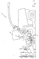
- a typical forage harvester In the harvester 1 shown schematically in Figure 1 is a typical forage harvester. In the direction of travel at the front of the forage harvester 1 is arranged a header 3, here for example a corn header for harvesting a corn field. By means of a cutting unit (not shown) of the attachment 3, the corn plants in a particular Height above the ground cut and then transported to the machine 1.
- a conveyor 6, consisting of two in the conveying direction R arranged behind one another Feed roller pairs 7, 8, 9, 10.
- the two front feed rollers 7 and 10 are also used to pre-press the crop G. You will therefore often referred to as pre-press rollers 7, 10.
- the crop G is then behind the second feed roller pair 8, 9 in the direction of a Humbleselaggregats 2, where the crop G is chopped and accelerated and then, if necessary, after a post-acceleration upwards over a Chute on a towed by the harvester trailer or a moving transport vehicle is ejected.
- a metal detection device 18 To prevent metal parts from entering the machine with the crop can and damage the machine 1 itself or impurities lead the crop, is located within the conveyor 6, here in the front lower feed roller 10, a metal detection device 18. Once in the metal detection device 18, a metal part in the crop G is detected, this outputs a signal, which is an immediate Stop the machine leads.
- the metal detection device 18 operates for this purpose with a measuring magnetic field M, which is aligned upward in the Erntegutstrom (Figure 3), so that the crop G passes through this measuring magnetic field M.
- Metallic Elements lead to a change in the measuring magnetic field M, which are detected by the metal detection device 18.
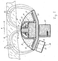
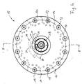
- a possible concrete construction of such a metal detection device 18 is in Explained below with reference to Figures 2 to 5, wherein Figure 3 is a mechanical Structure and Figure 2 shows a circuit construction.
- the Figures 4 and 5 show the arrangement of this specific structure within the feed roller 10.
- a core of the metal detection device 18 is a magnet assembly 19, which consists of several in a row transverse to the conveying direction R of the crop G consists of juxtaposed individual magnets, here each. with their north pole N up and their south pole S pointing down.
- a magnet assembly 19 is located on a metal wall 25, hereinafter Also called magnet tray 25, which is also over the entire Width transversely to the conveying direction R of the crop G extends ( Figure 5).
- pole shoes 20 On the upper side of the magnet arrangement 19 there are a plurality of pole shoes 20. These each have a lower, broad section, which rests on the north pole side of the magnet arrangement 19, and an upper narrow section. The upper sections of the pole pieces 20 each project into individual coils 21 1 ,..., 21 8 (FIG. 2). These coils 21 1 ,..., 21 8 form the sensor arrangement 21 in order to register changes in the measuring magnetic field M. In total, these are eight individual pole shoes 20 with eight different coils 21 1 ,..., 21 8 , which cover the entire width transversely to the conveying direction R with their detection areas a, b, c, d, e, f, g. This is shown schematically in FIG. The eight coils 21 1 ,..., 21 8 are each double coils with two windings, although in each case only one winding is used by the first and last coil 21 1 , 21 8 .
- the magnetic field lines ML of the measuring magnetic field M extend from the north pole N of the magnet arrangement 19 through the individual pole shoes 20 - and thus through the coils 21 1 ,..., 21 8 of the sensor device 21 - upwards the crop G and back via the magnet well 25 to the south pole S of the magnet assembly 19.
- a change of the measuring magnetic field M by metal parts in the crop G thus leads to that in the coils 21 1 , ..., 21 8 , in the detection area a , b, c, d, e, f, g the measurement magnetic field change occurs, a current is induced, which can then be tapped and evaluated as signal S.
- brackets 23 serve to hold the coils 21 1 ,..., 21 8 with the magnet arrangement 19 and the pole shoes 20 thereon against the magnet tub 25.
- the entire structure is poured into a potting compound 24 and thus largely protected from damage in the rough harvesting operation.
- the magnet well 25 itself is arranged on a rigid support shaft 11 within the lower feed roller 10. The exact position and position will be explained later with reference to Figures 4 and 5.
- the signal evaluation of the individual signals S of the coils 21 1 ,..., 21 8 of the sensor arrangement 21 takes place in a signal evaluation device 30.
- This can be directly in the metal detection device 18, for example on a between the lower part of the pole pieces 20 and the coils of the sensor assembly 21st arranged board 22 may be arranged ( Figure 3). However, it can also be located outside the metal detection device 18, for example in a processor of a control device of the machine 1.
- parts of the signal evaluation device 30, for example preamplifier or the like, on the board 22 in the metal detection device 18 and other parts of the evaluation device 30 externally in a separate device within the harvester 1, in particular in the central control device the machine 1, are housed.
- This shuttering causes disturbances that affect all coils 21 1 , ..., 21 8 , such as a uniform magnetic field change over the entire width of the feed unit, in all coils 21 1 , ..., 21 8 registered the same ,
- the induced currents then cancel each other out at the differential amplification so that such events are not registered. If a change in magnetic field, however, only in a part of the individual detection areas a, ..., g, then, this leads to that only part of the coils 21 1, ..., 21 8, a current is induced, which in some of the each other adjacent coils 21 1 , ..., 21 8 different strong currents are induced. This results in a difference signal which is amplified in the amplifiers 31.
- the output signals AS of the amplifiers 31 are applied to analog / digital converters 32 forwarded, in each of which a threshold adjustable is. Only if the analog input signal AS this adjustable threshold exceeds, at the output of the analog / digital converter 32 is a digital Output DS output, which then to an evaluation processor 33 is handed over. This is the output side, a stop signal SS to a corresponding rapid stop circuit 34 of the machine off, as soon as a digital Input signal DS at one of the with the analog / digital converters 32nd connected inputs occurs.
- the quick stop circuit 34 then ensures an immediate stop of the conveyor 6 or the entire harvester 1.
- the conveyor 6 In order to avoid such false triggering, the conveyor 6 according to the invention an additional interference sensor device 26.
- This registered especially those disruptive events that are not caused by metal parts in the crop G caused by the sensor assembly 21 registered magnetic field change and then gives a false trip warning signal F out.
- This false trip warning signal F is, for example, to the evaluation processor 33 transmitted (see Figure 2) and leads there that the output a stop signal SS in a certain subsequent period the quick stop circuit 34 is suppressed.
- this false trip signal F also directly to the analog / digital converter 32 output be there to raise the adjustable threshold, so that the signal evaluation device 30 and thus the entire metal detection device 18 becomes less sensitive. Preferably, it is ensured that after a certain period of a few seconds the adjustable Threshold is automatically lowered again.
- Figure 4 shows an axial view of the arrangement of the magnet well 25 with the therein magnet assembly 19, the pole pieces 20, the sensor assembly 21 etc. within the lower front feed roller 10 of the conveyor and Figure 5 is a view of this arrangement from the front in the conveying direction considered.
- the feed roller 10 consists of two end-side disc-shaped roller flanges 12a, 12b.
- first roller flange 12a is an outward attached extending shaft 15 which rotatably mounted in the machine is and which serves as a drive shaft.
- the second roll flange 12b is by means of a bearing 16 mounted on a rigid axle 11 which extends through the entire roller 10 extends and rotates end in a recess in the first roller flange 12a connected to the shaft 15 is stored.
- the drive shaft 15 and the rigid shaft 11 are coaxial arranged to each other.
- the two roller flanges 12a and 12b are respectively over several angular, parallel to the roll axis 11 extending Roll profiles 14 connected to each other.
- roller profiles 14 are along the circumference of the roller 10 evenly distributed, thus forming a closed Lateral surface with a blade-like profiling to the crop G in the desired manner between the roller pairs 7, 10, 8, 9th through the conveyor 6 to pull.
- the exact shape of the profiling can be best seen in Figure 4.
- the individual conveyor profiles 14 are here each end by means of screws 13 with the roller flanges 12a, 12b connected.
Landscapes
- Life Sciences & Earth Sciences (AREA)
- Engineering & Computer Science (AREA)
- Physics & Mathematics (AREA)
- Remote Sensing (AREA)
- Geology (AREA)
- Environmental & Geological Engineering (AREA)
- Electromagnetism (AREA)
- General Life Sciences & Earth Sciences (AREA)
- General Physics & Mathematics (AREA)
- Geophysics (AREA)
- Environmental Sciences (AREA)
- Geophysics And Detection Of Objects (AREA)
- Harvesting Machines For Root Crops (AREA)
- Forging (AREA)
Abstract
Description
- 1
- Erntemaschine
- 2
- Häckselaggregat
- 3
- Vorsatzgerät
- 4
- Führerhaus
- 5
- Anzeigeeinrichtung
- 6
- Förderer
- 7
- Einzugswalzen
- 8
- Einzugswalzen
- 9
- Einzugswalzen
- 10
- Einzugswalzen
- 11
- Achse
- 12a
- Walzenflansch
- 12b
- Walzenflansch
- 13
- Schraube
- 14
- Walzenprofil
- 15
- Antriebswelle
- 16
- Lager
- 17
- Durchführung
- 18
- Metalldetektionseinrichtung
- 19
- Magnetanordnung
- 20
- Polschuh
- 21
- Sensoranordnung
- 211,..., 218
- Spulen
- 22
- Platine
- 23
- Klammer
- 24
- Vergussmasse
- 25
- Metallwand / Magnetwanne
- 26
- Störsensoreinrichtung
- 27
- Magnetsensor
- 28
- Polschuh
- 29
- Beschleunigungssensor
- 30
- Signalauswerteeinrichtung
- 31
- Differenzverstärker
- 32
- Analog-/Digitalwandler
- 33
- Auswerteprozessor
- 34
- Schnellstoppschaltung
- 35
- Störsensorauswerteschaltung
- A
- analoges Eingangssignal
- D
- digitales Ausgangssignal
- F
- Fehlauslösewarnsignal
- G
- Erntegut
- ML
- Magnetfeldlinien
- N
- Nordpol
- R
- Förderrichtung
- S
- Südpol
- SS
- Stoppsignal
- a, b, c, d, e, f, g
- Detektionsbereiche
Claims (17)
- Förderer (6) mit einer Metalldetektionseinrichtung (18) zum Detektieren von Metallteilen in einem zu fördernden Gut (G),gekennzeichnet durchmit einer Magnetanordnung (19) zum Erzeugen eines Mess-Magnetfelds (M), durch welches das zu fördernde Gut (G) bewegt wird,mit einer Sensoranordnung (21), welche eine Veränderung des Mess-Magnetfelds (M) registriert,und einer Signalauswerteeinrichtung (30), welche ein bei einer Magnetfeldänderung von der Sensoranordnung (21) ausgegebenes Signal (S) zur Erkennung eines Metallteils im zu fördernden Gut (G) auswertet,
eine Störsensoreinrichtung (26), welche bei einer Registrierung eines Störereignisses, das zu einer nicht durch Metallteile im zu fördernden Gut (G) hervorgerufenen, von der Sensoranordnung (21) registrierten Magnetfeldveränderung führt, ein Fehlauslösewarnsignal (F) ausgibt. - Förderer nach Anspruch 1,
dadurch gekennzeichnet, dass
die Störsensoreinrichtung (26) einen Magnetfeldsensor (27) umfasst, welcher so ausgebildet und/oder angeordnet ist, dass er im Wesentlichen nur solche Magnetfeldänderungen registriert, die nicht durch Metallteile im zu fördernden Gut (G) hervorgerufen werden. - Förderer nach Anspruch 2,
dadurch gekennzeichnet, dass
der Magnetfeldsensor (27) eine Veränderung eines externen Magnetfelds registriert. - Förderer nach Anspruch 3,
dadurch gekennzeichnet, dass
die Feldlinien des von der Magnetanordnung (19) der Metalldetektionseinrichtung (18) erzeugten Mess-Magnetfelds (M) im Wesentlichen auf einer ersten Seite der Metalldetektionseinrichtung (18) durch das vorbeigeförderte Gut (G) verlaufen und die Sensoranordnung (21) der Metalldetektionseinrichtung (18) in diesem Mess-Magnetfeld (M) angeordnet ist und der Magnetfeldsensor (27) der Störsensoreinrichtung (26) auf einer vom Mess-Magnetfeld (M) abgewandten Seite der Metalldetektionseinrichtung (18) angeordnet ist. - Förderer nach Anspruch 4,
dadurch gekennzeichnet, dass
die Metalldetektionseinrichtung (18) eine auf einer dem vorbeibeförderten Gut (G) abgewandten Seite der Magnetanordnung (19) befindliche Metallwand (25) aufweist, welche die Magnetfeldlinien (ML) des Mess-Magnetfelds (M) sammelt und in Richtung der Magnetanordnung (19) leitet, und der Magnetfeldsensor (27) der Störsensoreinrichtung (26) auf der von der Magnetanordnung (19) abgewandten Seite der Metallwand (25) angeordnet ist. - Förderer nach einem der Ansprüche 1 bis 5,
dadurch gekennzeichnet, dass
die Störsensoreinrichtung (26) einen Beschleunigungssensor (29) umfasst. - Förderer nach einem der Ansprüche 1 bis 6,
dadurch gekennzeichnet, dass
die Störsensoreinrichtung (26) entlang einer quer zu einer Gutflussrichtung (R) verlaufenden Richtung mehrere an verschiedenen Positionen angeordnete Sensoren (27, 29) aufweist. - Förderer nach einem der Ansprüche 1 bis 7,
dadurch gekennzeichnet, dass
die Signalauswerteeinrichtung (30) derart ausgebildet ist, dass unter Verwendung eines von der Störsensoreinrichtung (26) empfangenen Fehlauslösewarnsignals (F) ein von der Sensoranordnung (21) der Metalldetektionseinrichtung (18) ausgegebenes Signal (S) korrigiert wird. - Förderer nach einem der Ansprüche 1 bis 8,
dadurch gekennzeichnet, dass
die Signalauswerteeinrichtung (30) derart ausgebildet ist, dass bei Empfang eines Fehlauslösewarnsignals (F) die Metalldetektionseinrichtung (18) vorübergehend deaktiviert wird oder die Empfindlichkeit der Metalldetektionseinrichtung (18) vorübergehend reduziert wird. - Förderer nach einem der Ansprüche 1 bis 9,
dadurch gekennzeichnet, dass
die Störsensoreinrichtung (26) mit einer Signalausgabeeinrichtung (5) verbunden ist, um das Fehlauslösewarnsignal (F) an einen Benutzer auszugeben. - Erntemaschine (1 ) mit einem Förderer (6) nach einem der Ansprüche 1 bis 10.
- Verfahren zum Detektieren von Metallteilen in einem zu fördernden Gut (G), bei dem das zu fördernde Gut (G) durch ein Mess-Magnetfeld (M) bewegt wird und mit einer Sensoranordnung (21) eine Veränderung des Mess-Magnetfelds (M) registriert wird und ein bei einer Magnetfeldänderung von der Sensoranordnung (21) ausgegebenes Signal (S) zur Erkennung eines Metallteils im zu fördernden Gut (G) ausgewertet wird,
dadurch gekennzeichnet, dass
mittels einer Störsensoreinrichtung (26) Störereignisse, die zu einer nicht durch Metallteile im zu fördernden Gut (G) hervorgerufenen, von der Sensoranordnung (21) gemessenen Magnetfeldveränderung führen, erkannt werden und bei einer Registrierung eines Störereignisses ein Fehlauslösewarnsignal (F) generiert wird. - Verfahren nach Anspruch 12,
dadurch gekennzeichnet, dass
als Störereignisse mittels eines Magnetfeldsensors (27) der Störsensoreinrichtung (26) nicht durch Metallteile im zu fördernden Gut (G) hervorgerufene Magnetfeldänderungen registriert werden. - Verfahren nach Anspruch 12 oder 13,
dadurch gekennzeichnet, dass
als Störereignisse an der Sensoranordnung (21) auftretende Beschleunigungskräfte registriert werden. - Verfahren nach einem der Ansprüche 12 bis 14,
dadurch gekennzeichnet, dass
unter Verwendung des Fehlauslösewarnsignals (F) der Störsensoreinrichtung (26) ein von der Sensoranordnung (21) der Metalldetektionseinrichtung (18) ausgegebenes Signal (S) korrigiert wird. - Verfahren nach einem der Ansprüche 12 bis 15,
dadurch gekennzeichnet, dass
bei Empfang eines Fehlauslösewarnsignals (F) die Metalldetektionseinrichtung (18) vorübergehend deaktiviert wird oder die Empfindlichkeit der Metalldetektionseinrichtung (18) vorübergehend reduziert wird. - Verfahren nach einem der Ansprüche 12 bis 16,
dadurch gekennzeichnet, dass
das Fehlauslösewarnsigrial (F) an einen Benutzer ausgegeben wird.
Applications Claiming Priority (2)
| Application Number | Priority Date | Filing Date | Title |
|---|---|---|---|
| DE10348659A DE10348659A1 (de) | 2003-10-15 | 2003-10-15 | Förderer mit einer Metalldetektionseinrichtung |
| DE10348659 | 2003-10-15 |
Publications (2)
| Publication Number | Publication Date |
|---|---|
| EP1523876A1 true EP1523876A1 (de) | 2005-04-20 |
| EP1523876B1 EP1523876B1 (de) | 2006-11-22 |
Family
ID=34353472
Family Applications (1)
| Application Number | Title | Priority Date | Filing Date |
|---|---|---|---|
| EP04023725A Expired - Lifetime EP1523876B1 (de) | 2003-10-15 | 2004-10-05 | Förderer mit einer Metalldetektionseinrichtung |
Country Status (4)
| Country | Link |
|---|---|
| US (1) | US7064540B2 (de) |
| EP (1) | EP1523876B1 (de) |
| AT (1) | ATE345669T1 (de) |
| DE (2) | DE10348659A1 (de) |
Cited By (3)
| Publication number | Priority date | Publication date | Assignee | Title |
|---|---|---|---|---|
| EP1997366A1 (de) * | 2007-05-30 | 2008-12-03 | CLAAS Selbstfahrende Erntemaschinen GmbH | Landwirtschaftliche Erntemaschine mit einer Fremdkörpererkennungsvorrichtung |
| BE1019497A5 (fr) * | 2008-12-10 | 2012-08-07 | Deere & Co | Dispositif de mise en evidence d'un corps etranger ayant penetre dans une machine de recolte. |
| EP3427570A1 (de) | 2017-07-11 | 2019-01-16 | CLAAS Selbstfahrende Erntemaschinen GmbH | Landwirtschaftliche erntemaschine, insbesondere feldhäcksler |
Families Citing this family (6)
| Publication number | Priority date | Publication date | Assignee | Title |
|---|---|---|---|---|
| DE102005005736A1 (de) * | 2005-02-07 | 2006-09-28 | Claas Selbstfahrende Erntemaschinen Gmbh | Metalldetektionseinrichtung |
| GB2430036A (en) * | 2005-09-09 | 2007-03-14 | Cnh Belgium Nv | Metal detector arrangement |
| US7748206B1 (en) | 2009-03-10 | 2010-07-06 | Cnh America Llc | Fruit harvester with system and method for detecting and reducing forces exerted against rigid standing objects |
| US8600480B2 (en) * | 2009-12-31 | 2013-12-03 | Mediguide Ltd. | System and method for assessing interference to a signal caused by a magnetic field |
| CN103533823A (zh) * | 2011-01-05 | 2014-01-22 | 哈萨克斯坦共和国教育科学部共和党公共企业“哈萨克国立农业大学” | 农作物脱粒方法 |
| US10579460B2 (en) * | 2016-11-28 | 2020-03-03 | Electronics And Telecommunications Research Institute | Method and apparatus for diagnosing error of operating equipment in smart farm |
Citations (3)
| Publication number | Priority date | Publication date | Assignee | Title |
|---|---|---|---|---|
| DE4301611A1 (de) * | 1991-09-02 | 1994-07-28 | Claas Ohg | Fremdkörpererkennungsvorrichtung einer Erntemaschine |
| EP0666021A1 (de) * | 1994-02-03 | 1995-08-09 | New Holland Belgium N.V. | Metalldetektionsapparat für Erntemaschine |
| US5901534A (en) * | 1996-05-22 | 1999-05-11 | Claas Kgaa | Metal detector for detecting metal in harvested product flow |
Family Cites Families (5)
| Publication number | Priority date | Publication date | Assignee | Title |
|---|---|---|---|---|
| US5600941A (en) * | 1995-03-31 | 1997-02-11 | New Holland North America, Inc. | Compensation for start-up transients |
| US5896031A (en) * | 1997-03-17 | 1999-04-20 | Thermo Sentron, Inc. | Quad coil vibration cancelling metal detector |
| DE19843608C1 (de) * | 1998-09-23 | 2000-03-16 | Claas Selbstfahr Erntemasch | Metallortungsvorrichtung in einem Erntegutförderer |
| DE19912407A1 (de) | 1999-03-19 | 2000-09-21 | Deere & Co | Förderer mit Metalldetektionseinrichtung |
| US6637179B2 (en) * | 2001-12-20 | 2003-10-28 | Kasha Farm Supplies Ltd. | Inertial system for detecting foreign objects between contra-rotating rolls |
-
2003
- 2003-10-15 DE DE10348659A patent/DE10348659A1/de not_active Withdrawn
-
2004
- 2004-10-05 AT AT04023725T patent/ATE345669T1/de not_active IP Right Cessation
- 2004-10-05 DE DE502004002070T patent/DE502004002070D1/de not_active Expired - Lifetime
- 2004-10-05 EP EP04023725A patent/EP1523876B1/de not_active Expired - Lifetime
- 2004-10-13 US US10/964,515 patent/US7064540B2/en not_active Expired - Fee Related
Patent Citations (3)
| Publication number | Priority date | Publication date | Assignee | Title |
|---|---|---|---|---|
| DE4301611A1 (de) * | 1991-09-02 | 1994-07-28 | Claas Ohg | Fremdkörpererkennungsvorrichtung einer Erntemaschine |
| EP0666021A1 (de) * | 1994-02-03 | 1995-08-09 | New Holland Belgium N.V. | Metalldetektionsapparat für Erntemaschine |
| US5901534A (en) * | 1996-05-22 | 1999-05-11 | Claas Kgaa | Metal detector for detecting metal in harvested product flow |
Cited By (4)
| Publication number | Priority date | Publication date | Assignee | Title |
|---|---|---|---|---|
| EP1997366A1 (de) * | 2007-05-30 | 2008-12-03 | CLAAS Selbstfahrende Erntemaschinen GmbH | Landwirtschaftliche Erntemaschine mit einer Fremdkörpererkennungsvorrichtung |
| RU2466527C2 (ru) * | 2007-05-30 | 2012-11-20 | КЛААС Зельбстфаренде Эрнтемашинен ГмбХ | Уборочная сельхозмашина с устройством обнаружения посторонних тел |
| BE1019497A5 (fr) * | 2008-12-10 | 2012-08-07 | Deere & Co | Dispositif de mise en evidence d'un corps etranger ayant penetre dans une machine de recolte. |
| EP3427570A1 (de) | 2017-07-11 | 2019-01-16 | CLAAS Selbstfahrende Erntemaschinen GmbH | Landwirtschaftliche erntemaschine, insbesondere feldhäcksler |
Also Published As
| Publication number | Publication date |
|---|---|
| DE10348659A1 (de) | 2005-06-30 |
| DE502004002070D1 (de) | 2007-01-04 |
| US20050083049A1 (en) | 2005-04-21 |
| ATE345669T1 (de) | 2006-12-15 |
| US7064540B2 (en) | 2006-06-20 |
| EP1523876B1 (de) | 2006-11-22 |
Similar Documents
| Publication | Publication Date | Title |
|---|---|---|
| DE102012223768B4 (de) | Fremdkörpernachweiseinrichtung für eine landwirtschaftliche Erntemaschine | |
| EP3363281B1 (de) | Erfassungsanordnung zur erfassung eines verschleisszustandes eines häckselwerks | |
| DE2265809C2 (de) | Erntemaschine mit einem Erkennungsgerät für metallische Fremdkörper | |
| DE3213713A1 (de) | Erkennungsgeraet fuer steine in erntemaschinen | |
| EP3498080B1 (de) | Feldhäcksler | |
| EP1442652B1 (de) | Einrichtung zur Messung und/oder Überprüfung des Abstands zwischen einer Gegenschneide und einem Häckselmesser | |
| DE3100045A1 (de) | Schutzvorrichtung fuer erntemaschinen | |
| EP1900273B1 (de) | Fremdkörpernachweiseinrichtung für eine landwirtschaftliche Erntemaschine | |
| DE102014218408A1 (de) | Anordnung zur Erfassung der Schärfe von Häckselmessern | |
| EP1523876B1 (de) | Förderer mit einer Metalldetektionseinrichtung | |
| DE3211819A1 (de) | Erkennungsgeraet fuer metallische fremdkoerper | |
| DE19742060A1 (de) | Fremdkörperrückführvorrichtung an Erntemaschinen o. dgl. | |
| DE102020129795A1 (de) | Feldhäcksler mit Konditionierwalzen und Verschleißsensor | |
| DE69509271T2 (de) | Metalldetektionsapparat für Erntemaschine | |
| EP3427570A1 (de) | Landwirtschaftliche erntemaschine, insbesondere feldhäcksler | |
| DE102005005736A1 (de) | Metalldetektionseinrichtung | |
| DE4301611C2 (de) | Fremdkörpererkennungsvorrichtung einer Erntemaschine | |
| EP2514299A1 (de) | Einrichtung zum Nachweis eines in eine Erntemaschine eingedrungenen Fremdkörpers | |
| EP3706546B1 (de) | Pick-up mit metalldetektor | |
| EP1621066B2 (de) | Schutzvorrichtung für landwirtschaftliche Arbeitsmaschinen | |
| EP1498019A1 (de) | Erntemaschine mit einer Metalldetektionseinrichtung | |
| BE1029616A1 (de) | Anordnung zur Erfassung der Schärfe und/oder des Abstands von Messern einer Häckseltrommel eines Feldhäckslers und deren Drehstellung und/oder Drehzahl | |
| BE1021657B1 (de) | Einzugszusammenbau für einen feldhäcksler | |
| EP0064566B1 (de) | Vorrichtung zum Erkennen von eisenhaltigem Material in Feldhäckslern | |
| EP1247441B1 (de) | Erntemaschine mit Metalldetektionseinrichtung |
Legal Events
| Date | Code | Title | Description |
|---|---|---|---|
| PUAI | Public reference made under article 153(3) epc to a published international application that has entered the european phase |
Free format text: ORIGINAL CODE: 0009012 |
|
| AK | Designated contracting states |
Kind code of ref document: A1 Designated state(s): AT BE BG CH CY CZ DE DK EE ES FI FR GB GR HU IE IT LI LU MC NL PL PT RO SE SI SK TR |
|
| AX | Request for extension of the european patent |
Extension state: AL HR LT LV MK |
|
| 17P | Request for examination filed |
Effective date: 20051020 |
|
| AKX | Designation fees paid |
Designated state(s): AT BE BG CH CY CZ DE DK EE ES FI FR GB GR HU IE IT LI LU MC NL PL PT RO SE SI SK TR |
|
| GRAP | Despatch of communication of intention to grant a patent |
Free format text: ORIGINAL CODE: EPIDOSNIGR1 |
|
| GRAS | Grant fee paid |
Free format text: ORIGINAL CODE: EPIDOSNIGR3 |
|
| GRAA | (expected) grant |
Free format text: ORIGINAL CODE: 0009210 |
|
| AK | Designated contracting states |
Kind code of ref document: B1 Designated state(s): AT BE BG CH CY CZ DE DK EE ES FI FR GB GR HU IE IT LI LU MC NL PL PT RO SE SI SK TR |
|
| PG25 | Lapsed in a contracting state [announced via postgrant information from national office to epo] |
Ref country code: IT Free format text: LAPSE BECAUSE OF FAILURE TO SUBMIT A TRANSLATION OF THE DESCRIPTION OR TO PAY THE FEE WITHIN THE PRESCRIBED TIME-LIMIT;WARNING: LAPSES OF ITALIAN PATENTS WITH EFFECTIVE DATE BEFORE 2007 MAY HAVE OCCURRED AT ANY TIME BEFORE 2007. THE CORRECT EFFECTIVE DATE MAY BE DIFFERENT FROM THE ONE RECORDED. Effective date: 20061122 Ref country code: RO Free format text: LAPSE BECAUSE OF FAILURE TO SUBMIT A TRANSLATION OF THE DESCRIPTION OR TO PAY THE FEE WITHIN THE PRESCRIBED TIME-LIMIT Effective date: 20061122 Ref country code: NL Free format text: LAPSE BECAUSE OF FAILURE TO SUBMIT A TRANSLATION OF THE DESCRIPTION OR TO PAY THE FEE WITHIN THE PRESCRIBED TIME-LIMIT Effective date: 20061122 Ref country code: IE Free format text: LAPSE BECAUSE OF FAILURE TO SUBMIT A TRANSLATION OF THE DESCRIPTION OR TO PAY THE FEE WITHIN THE PRESCRIBED TIME-LIMIT Effective date: 20061122 Ref country code: PL Free format text: LAPSE BECAUSE OF FAILURE TO SUBMIT A TRANSLATION OF THE DESCRIPTION OR TO PAY THE FEE WITHIN THE PRESCRIBED TIME-LIMIT Effective date: 20061122 Ref country code: FI Free format text: LAPSE BECAUSE OF FAILURE TO SUBMIT A TRANSLATION OF THE DESCRIPTION OR TO PAY THE FEE WITHIN THE PRESCRIBED TIME-LIMIT Effective date: 20061122 Ref country code: SK Free format text: LAPSE BECAUSE OF FAILURE TO SUBMIT A TRANSLATION OF THE DESCRIPTION OR TO PAY THE FEE WITHIN THE PRESCRIBED TIME-LIMIT Effective date: 20061122 Ref country code: CZ Free format text: LAPSE BECAUSE OF FAILURE TO SUBMIT A TRANSLATION OF THE DESCRIPTION OR TO PAY THE FEE WITHIN THE PRESCRIBED TIME-LIMIT Effective date: 20061122 Ref country code: SI Free format text: LAPSE BECAUSE OF FAILURE TO SUBMIT A TRANSLATION OF THE DESCRIPTION OR TO PAY THE FEE WITHIN THE PRESCRIBED TIME-LIMIT Effective date: 20061122 |
|
| REG | Reference to a national code |
Ref country code: GB Ref legal event code: FG4D Free format text: NOT ENGLISH |
|
| REG | Reference to a national code |
Ref country code: CH Ref legal event code: EP |
|
| REG | Reference to a national code |
Ref country code: IE Ref legal event code: FG4D Free format text: LANGUAGE OF EP DOCUMENT: GERMAN |
|
| REF | Corresponds to: |
Ref document number: 502004002070 Country of ref document: DE Date of ref document: 20070104 Kind code of ref document: P |
|
| PG25 | Lapsed in a contracting state [announced via postgrant information from national office to epo] |
Ref country code: BG Free format text: LAPSE BECAUSE OF FAILURE TO SUBMIT A TRANSLATION OF THE DESCRIPTION OR TO PAY THE FEE WITHIN THE PRESCRIBED TIME-LIMIT Effective date: 20070222 Ref country code: DK Free format text: LAPSE BECAUSE OF FAILURE TO SUBMIT A TRANSLATION OF THE DESCRIPTION OR TO PAY THE FEE WITHIN THE PRESCRIBED TIME-LIMIT Effective date: 20070222 Ref country code: SE Free format text: LAPSE BECAUSE OF FAILURE TO SUBMIT A TRANSLATION OF THE DESCRIPTION OR TO PAY THE FEE WITHIN THE PRESCRIBED TIME-LIMIT Effective date: 20070222 |
|
| PG25 | Lapsed in a contracting state [announced via postgrant information from national office to epo] |
Ref country code: ES Free format text: LAPSE BECAUSE OF FAILURE TO SUBMIT A TRANSLATION OF THE DESCRIPTION OR TO PAY THE FEE WITHIN THE PRESCRIBED TIME-LIMIT Effective date: 20070305 |
|
| ET | Fr: translation filed | ||
| PG25 | Lapsed in a contracting state [announced via postgrant information from national office to epo] |
Ref country code: PT Free format text: LAPSE BECAUSE OF FAILURE TO SUBMIT A TRANSLATION OF THE DESCRIPTION OR TO PAY THE FEE WITHIN THE PRESCRIBED TIME-LIMIT Effective date: 20070423 |
|
| NLV1 | Nl: lapsed or annulled due to failure to fulfill the requirements of art. 29p and 29m of the patents act | ||
| GBV | Gb: ep patent (uk) treated as always having been void in accordance with gb section 77(7)/1977 [no translation filed] |
Effective date: 20061122 |
|
| REG | Reference to a national code |
Ref country code: IE Ref legal event code: FD4D |
|
| PLBE | No opposition filed within time limit |
Free format text: ORIGINAL CODE: 0009261 |
|
| STAA | Information on the status of an ep patent application or granted ep patent |
Free format text: STATUS: NO OPPOSITION FILED WITHIN TIME LIMIT |
|
| 26N | No opposition filed |
Effective date: 20070823 |
|
| PG25 | Lapsed in a contracting state [announced via postgrant information from national office to epo] |
Ref country code: GB Free format text: LAPSE BECAUSE OF FAILURE TO SUBMIT A TRANSLATION OF THE DESCRIPTION OR TO PAY THE FEE WITHIN THE PRESCRIBED TIME-LIMIT Effective date: 20061122 |
|
| PG25 | Lapsed in a contracting state [announced via postgrant information from national office to epo] |
Ref country code: GR Free format text: LAPSE BECAUSE OF FAILURE TO SUBMIT A TRANSLATION OF THE DESCRIPTION OR TO PAY THE FEE WITHIN THE PRESCRIBED TIME-LIMIT Effective date: 20070223 |
|
| PG25 | Lapsed in a contracting state [announced via postgrant information from national office to epo] |
Ref country code: MC Free format text: LAPSE BECAUSE OF NON-PAYMENT OF DUE FEES Effective date: 20071031 |
|
| PG25 | Lapsed in a contracting state [announced via postgrant information from national office to epo] |
Ref country code: EE Free format text: LAPSE BECAUSE OF FAILURE TO SUBMIT A TRANSLATION OF THE DESCRIPTION OR TO PAY THE FEE WITHIN THE PRESCRIBED TIME-LIMIT Effective date: 20061122 |
|
| PG25 | Lapsed in a contracting state [announced via postgrant information from national office to epo] |
Ref country code: AT Free format text: LAPSE BECAUSE OF NON-PAYMENT OF DUE FEES Effective date: 20071005 |
|
| PGRI | Patent reinstated in contracting state [announced from national office to epo] |
Ref country code: IT Effective date: 20081101 |
|
| REG | Reference to a national code |
Ref country code: CH Ref legal event code: PL |
|
| PG25 | Lapsed in a contracting state [announced via postgrant information from national office to epo] |
Ref country code: LU Free format text: LAPSE BECAUSE OF NON-PAYMENT OF DUE FEES Effective date: 20071005 Ref country code: CY Free format text: LAPSE BECAUSE OF FAILURE TO SUBMIT A TRANSLATION OF THE DESCRIPTION OR TO PAY THE FEE WITHIN THE PRESCRIBED TIME-LIMIT Effective date: 20061122 |
|
| PG25 | Lapsed in a contracting state [announced via postgrant information from national office to epo] |
Ref country code: TR Free format text: LAPSE BECAUSE OF FAILURE TO SUBMIT A TRANSLATION OF THE DESCRIPTION OR TO PAY THE FEE WITHIN THE PRESCRIBED TIME-LIMIT Effective date: 20061122 Ref country code: HU Free format text: LAPSE BECAUSE OF FAILURE TO SUBMIT A TRANSLATION OF THE DESCRIPTION OR TO PAY THE FEE WITHIN THE PRESCRIBED TIME-LIMIT Effective date: 20070523 |
|
| PG25 | Lapsed in a contracting state [announced via postgrant information from national office to epo] |
Ref country code: CH Free format text: LAPSE BECAUSE OF NON-PAYMENT OF DUE FEES Effective date: 20081031 Ref country code: LI Free format text: LAPSE BECAUSE OF NON-PAYMENT OF DUE FEES Effective date: 20081031 |
|
| REG | Reference to a national code |
Ref country code: FR Ref legal event code: PLFP Year of fee payment: 12 |
|
| REG | Reference to a national code |
Ref country code: FR Ref legal event code: PLFP Year of fee payment: 13 |
|
| REG | Reference to a national code |
Ref country code: FR Ref legal event code: PLFP Year of fee payment: 14 |
|
| PGFP | Annual fee paid to national office [announced via postgrant information from national office to epo] |
Ref country code: FR Payment date: 20171024 Year of fee payment: 14 |
|
| PGFP | Annual fee paid to national office [announced via postgrant information from national office to epo] |
Ref country code: IT Payment date: 20171023 Year of fee payment: 14 |
|
| REG | Reference to a national code |
Ref country code: DE Ref legal event code: R084 Ref document number: 502004002070 Country of ref document: DE |
|
| PGFP | Annual fee paid to national office [announced via postgrant information from national office to epo] |
Ref country code: DE Payment date: 20180911 Year of fee payment: 15 |
|
| PGFP | Annual fee paid to national office [announced via postgrant information from national office to epo] |
Ref country code: BE Payment date: 20181019 Year of fee payment: 15 |
|
| PG25 | Lapsed in a contracting state [announced via postgrant information from national office to epo] |
Ref country code: FR Free format text: LAPSE BECAUSE OF NON-PAYMENT OF DUE FEES Effective date: 20181031 |
|
| PG25 | Lapsed in a contracting state [announced via postgrant information from national office to epo] |
Ref country code: IT Free format text: LAPSE BECAUSE OF FAILURE TO SUBMIT A TRANSLATION OF THE DESCRIPTION OR TO PAY THE FEE WITHIN THE PRESCRIBED TIME-LIMIT Effective date: 20181005 |
|
| REG | Reference to a national code |
Ref country code: DE Ref legal event code: R119 Ref document number: 502004002070 Country of ref document: DE |
|
| PG25 | Lapsed in a contracting state [announced via postgrant information from national office to epo] |
Ref country code: DE Free format text: LAPSE BECAUSE OF NON-PAYMENT OF DUE FEES Effective date: 20200501 |
|
| REG | Reference to a national code |
Ref country code: BE Ref legal event code: MM Effective date: 20191031 |
|
| PG25 | Lapsed in a contracting state [announced via postgrant information from national office to epo] |
Ref country code: BE Free format text: LAPSE BECAUSE OF NON-PAYMENT OF DUE FEES Effective date: 20191031 |