EP1523872B2 - Machine de travail agricole - Google Patents
Machine de travail agricole Download PDFInfo
- Publication number
- EP1523872B2 EP1523872B2 EP04104952.9A EP04104952A EP1523872B2 EP 1523872 B2 EP1523872 B2 EP 1523872B2 EP 04104952 A EP04104952 A EP 04104952A EP 1523872 B2 EP1523872 B2 EP 1523872B2
- Authority
- EP
- European Patent Office
- Prior art keywords
- working
- operating mode
- road
- operator
- controller
- Prior art date
- Legal status (The legal status is an assumption and is not a legal conclusion. Google has not performed a legal analysis and makes no representation as to the accuracy of the status listed.)
- Expired - Lifetime
Links
- 239000004459 forage Substances 0.000 claims description 5
- 238000003306 harvesting Methods 0.000 claims description 4
- 239000000463 material Substances 0.000 claims description 2
- 241001124569 Lycaenidae Species 0.000 description 5
- 230000007704 transition Effects 0.000 description 2
- 229920000742 Cotton Polymers 0.000 description 1
- 240000008042 Zea mays Species 0.000 description 1
- 235000005824 Zea mays ssp. parviglumis Nutrition 0.000 description 1
- 235000002017 Zea mays subsp mays Nutrition 0.000 description 1
- 235000005822 corn Nutrition 0.000 description 1
- 230000007613 environmental effect Effects 0.000 description 1
- 239000003337 fertilizer Substances 0.000 description 1
- 238000005286 illumination Methods 0.000 description 1
- -1 seeders Substances 0.000 description 1
- 238000000926 separation method Methods 0.000 description 1
- 239000004575 stone Substances 0.000 description 1
- 238000003971 tillage Methods 0.000 description 1
- 230000001755 vocal effect Effects 0.000 description 1
Images
Classifications
-
- A—HUMAN NECESSITIES
- A01—AGRICULTURE; FORESTRY; ANIMAL HUSBANDRY; HUNTING; TRAPPING; FISHING
- A01D—HARVESTING; MOWING
- A01D41/00—Combines, i.e. harvesters or mowers combined with threshing devices
- A01D41/12—Details of combines
- A01D41/127—Control or measuring arrangements specially adapted for combines
-
- A—HUMAN NECESSITIES
- A01—AGRICULTURE; FORESTRY; ANIMAL HUSBANDRY; HUNTING; TRAPPING; FISHING
- A01B—SOIL WORKING IN AGRICULTURE OR FORESTRY; PARTS, DETAILS, OR ACCESSORIES OF AGRICULTURAL MACHINES OR IMPLEMENTS, IN GENERAL
- A01B63/00—Lifting or adjusting devices or arrangements for agricultural machines or implements
-
- A—HUMAN NECESSITIES
- A01—AGRICULTURE; FORESTRY; ANIMAL HUSBANDRY; HUNTING; TRAPPING; FISHING
- A01B—SOIL WORKING IN AGRICULTURE OR FORESTRY; PARTS, DETAILS, OR ACCESSORIES OF AGRICULTURAL MACHINES OR IMPLEMENTS, IN GENERAL
- A01B73/00—Means or arrangements to facilitate transportation of agricultural machines or implements, e.g. folding frames to reduce overall width
Definitions
- the invention relates to an agricultural working machine according to the preamble of claim 1.
- Agricultural work machines such as tractors, forage harvesters, combine harvesters, cotton ploughs, and the like, are generally operable to work in a field and to transport on a road.
- Many of these machines (see manual 6650, 6750, 6850 and 6950 Self-Propelled Forage Harvester, John Deere Werke Zweimaschinen OMZ92565 Edition K7 ⁇ 1997) have operator input devices, which are usually designed as so-called field / road switches or road safety switches. These operator input devices make it possible to select a working mode. Only when the working mode is selected, can certain operations of the working machine required on the field be put into operation, in a combine harvester, for example, the unloading conveyor is set in rotation and the emptying tube is swung out.
- the operator input device makes it possible to select a road mode. Only in the road mode, in turn, other facilities needed only in road mode can be turned on, such as certain lights. In the road mode, the equipment required only at the time of operation can not be turned on, while in the work mode, the equipment of the work machine required only when traveling on a road can not be put into operation. In this way, operator errors are avoided.
- the operator wants to enter the road mode after completion of work on a field, he must first pass a working device from the operating position to an inoperative position by operating a corresponding switch in many types of work machines, whereupon an actuator moves the working device to the inoperative position ,
- the unloading tube is to be set in the position in which it extends along one side of the combine harvester. A ride on a road is now safely possible, while it would not be permitted with swung discharge tube.
- an agricultural machine is described with a working device that can be raised by an actuator.
- the actuator is connected to a controller, which in turn is connected to an input device.
- the input device can be changed via the controller and the actuator, the vertical position of the implement.
- the controller may check to see if the implement is in a raised position suitable for road travel. If these conditions are met and the speed is greater than a minimum value, a so-called road mode is entered in which it is checked whether the unwanted vibrations of the implement actually occur and possibly the actuator is lowered to lower the implement in order to prevent the vibrations ,
- the object underlying the invention is seen to avoid the disadvantages mentioned.
- a controller is connected to the operator input device.
- the controller is also supplied with information about the position of the working device. If the operator causes a transition from the working mode to the street mode by operating the operator input device, the controller checks whether the operating device is in the inoperative position. Depending on the result of the comparison, a signal value is generated.
- the actuator On the basis of the signal value, it is possible to automatically control the actuator intended for moving the working device and to cause the working device to be in the inoperative position, if the operator input device selects a transition from the road mode to the working mode and the working device is not already in the operating mode Is inoperative position. Alternatively or additionally, the operator is given appropriate information so that he can initiate a provision of the working device.
- the working device passes automatically or by operator action in the to be taken during road travel inoperative position.
- the work of the operator is much easier, the likelihood of errors is reduced and the safety on the road is guaranteed.
- the invention is particularly applicable to self-propelled harvesters such as combine harvesters, forage harvesters and balers.
- the working element is preferably designed for handling crop, ie for picking up, transporting or processing the crop, ie it is then not means for propelling the machine.
- the operator input device may drive an actuator which moves the discharge tube, the grain tank cover, a wheel assembly that is adjustable to work on a slope, and / or moves the harvesting attachment to a non-operational position.
- One or more of the said working devices are thus automatically or manually moved to the inoperative position as soon as the operator selects the road mode with the operator input device.
- the lifting device rotatable about the vertical axis and adjustable in inclination, downstream of the chopping device, and / or the elements of a header mounted for transporting the road into an inoperative position can be moved.
- the invention may also find use on tractors with attached tillage tools or equipment for spreading material, such as seeders, fertilizer spreaders or sprayers, which may be moved to the inoperative position.
- a corresponding sensor which is suitable to detect a condition in which a movement of the working device in the inoperative position is not useful or not possible.
- a sensor can be a sufficiently well-known fill level sensor.
- the sensor is connected to a controller which is also connected to the actuator and the operator input device. If necessary, the sensor transmits a corresponding signal to the controller, which indicates that actuation of the actuator does not make sense.
- the controller if receiving a signal from the operator input device instructing it to move the actuator toward the inoperative position, inhibits actuation of the actuator if the sensor provides a signal indicative of the occurrence of the condition. Instead of actuating the actuator, the controller gives an appropriate indication to the operator so that he can first remove the obstacle, for. B. empty the grain tank.
- an operator input element for actuating the actuator is in a position corresponding to a working element in the operating position and the operator causes the operator to move the working element into the inoperative position by means of the operator input device, it makes sense to do so Automatically spend operator input element in a position corresponding to an inoperative position of the working element. This prevents the working element from automatically and unintentionally reaching the operating position as soon as the operator again selects the operating mode with the operator input device.
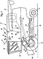
- FIG. 1 An in FIG. 1 shown self-propelled work machine 10 in the form of a combine is supported on front driven and rear steerable means 12 and 14 for propulsion in the form of wheels and has a driver's cab 16, from which it can be operated by a driver.
- a grain tank 18 connects at the rear, which can deliver good discharged into it via a grain tank emptying tube 20 to the outside.
- the grain tank 18 rests on a frame 22, in the supplied good on the way via a threshing drum 24, a concave 26 and a beater 28 is decomposed into its large and small components.
- the Korntankentleerrohr 20 is rotatable by a first actuator 42 in the form of a hydraulic motor about the vertical axis, so that it between the in the FIG. 1 illustrated inoperative position in which it extends along the side of the work machine 10, and an operating position in which it is with respect to the FIG. 1 extends perpendicular to the plane, is movable.
- the grain tank evacuation pipe 20 may be used to deliver the grain stored in the grain tank 18 to a trailer or other container.
- a grain tank cover 44 At the top of the grain tank 18 is a grain tank cover 44 in the form of pivotable cover elements.
- the Korntankabdeckung 44 can by its associated second actuator 46 in the form of a hydraulic cylinder, which is connected by a suitable mechanism with the Korntankabdeckung 44, between an operating position, as shown in the FIG. 1 and in which the grain tank cover 44 is opened to increase the capacity of the grain tank 18, and an inoperative position in which the grain tank cover 44 is closed and the interior of the grain tank 18 is protected from environmental influences.
- the height of the work machine 10 is then reduced to the height allowed for participation in road traffic.
- Within the grain tank is a level sensor 50.
- the grain tank emptying tube 20 and the grain tank cover 44 thus form working devices that are movable by the associated actuators 42, 46 between an operating position for working on a field and an inoperative position for traveling on a road.
- a lighting 48 At the front of the cab 16 is a lighting 48, which is only to take on a road trip in operation.
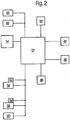
- the FIG. 2 schematically shows a part of the control electronics of the work machine 10. It comprises a controller 52 in the form of a microprocessor o. ⁇ ., Which is connected via not shown, electromagnetic control valves to the actuators 42, 46. In addition, the controller 52 is connected to the level sensor 50 of the grain tank 18 and the lighting 48. An operator input device 54, a switch 56 for pivoting the grain tank emptying pipe 20, a switch 58 for opening and closing the grain tank cover 44 and a switch 60 for the lighting 48 are also connected to the controller 52. The connections mentioned are preferably made via a bus system not shown.
- the operator input device 54 is a switch which, like the other switches 56-60, is arranged in the driver's cab 16 in the grip area of an operator.
- the operator input device is manually operable by the operator in a road mode position and, alternatively, in a work mode position.
- any other form of operator input device may be selected, such as a keyboard, a touch-sensitive screen, or a voice input device.
- the controller 52 is programmed such that the illumination 48 can be turned on by the switch 60 only when the operator input device 54 is in the street mode position. There may also be various other devices of the work machine 10 that can be brought into a mode of operation by respective switches only when the operator input device 54 is in the road mode position, such as turn signals and the like. When the operator input device 54 is in the working mode position, the lighting 48 is turned off regardless of the position of the switch 60.
- the controller 52 causes the grain tank emptying tube 20 to pivot through the actuator 42 only when the operator input device 54 is in the working mode position.
- the actuator 42 is turned off regardless of the position of the switch 60.
- the controller 52 further causes actuation of the switch 58 to pivot the grain tank cover 44 by the actuator 46 when the operator input device 54 is in the work mode position.
- the actuator 46 is turned off regardless of the position of the switch 58.
- work devices that can only be put into operation when the operator input device 54 is in the work mode position, such as the threshing cylinder 24 and the shakers 30.
- the controller 52 is configured to check, after switching the operator input device 54 from the working mode position to the road mode position, whether the grain tank exhaust pipe 20 is in its inoperative position. If this is not the case, the actuator 42 is automatically activated until it has spent the grain tank emptying tube 20 in the inoperative position.
- a corresponding sensor 66 for the position of the grain tank emptying tube 20 is connected to the controller 52.
- an electromechanical actuator 62 is provided, which then spends the switch 56 in the position corresponding to the rest position of the grain tank emptying tube 20.
- the position of the grain tank emptying tube 20 can alternatively or additionally also be displayed on a screen, wherein an operator is presented with the input elements available for selection at the respective time adjustment options.
- the controller 52 checks whether the grain tank cover 44 is in its inoperative position. If this is not the case, the sensor 50 is queried. If its signal indicates that the grain tank 18 is too filled to close the grain tank cover 44 easily, the operator is given appropriate information, for example by a control lamp or written or verbal text information. If necessary, the operator may first perform an emptying of the grain tank 18. On the other hand, if the signal from the sensor 50 indicates that the grain tank 18 is not filled to a degree hindering the closing of the grain tank cover 44, the controller 52 causes the actuator 46 to close the grain tank cover 44. An actuator 64 also spends the switch 58 in the position corresponding to the inoperative position of the grain tank cover 44.
- a suitable sensor 68 for sensing the position of the grain tank cover 44 is provided and connected to the controller 52.
- the position of the grain tank cover 44 can Alternatively or additionally, also be displayed on a screen, with an operator currently displayed with input elements for selection adjustment options are displayed
- the invention enables automatic resetting of the grain tank emptying tube 20 and corn tank cover 44 working equipment to the inoperative position when shifting from the working mode to the road mode.
- the operation of the work machine 10 is simplified and the safety in the road mode is increased because no work equipment can accidentally remain in the operating position.
Landscapes
- Life Sciences & Earth Sciences (AREA)
- Environmental Sciences (AREA)
- Engineering & Computer Science (AREA)
- Mechanical Engineering (AREA)
- Soil Sciences (AREA)
- Combines (AREA)
- Safety Devices And Accessories For Harvesting Machines (AREA)
Claims (6)
- Machine de travail agricole (10) présentant :des moyens (12, 14) permettant l'avancement de l'machine de travail (10),un dispositif de travail qui peut être amené par un actionneur (42, 46) dans une position de fonctionnement pour travailler sur un terrain et qui peut être amené dans une position de non fonctionnement en vue d'un déplacement sur une chaussée etun dispositif (54) de commande de fonctionnement relié à une commande (52) et avec lequel un opérateur peut sélectionner le mode de fonctionnement de l'machine de travail (10), l'opérateur disposant au moins d'un mode de fonctionnement sur chaussée et d'un mode de fonctionnement de travail,la commande (52) étant programmée de telle sorte que des dispositifs de l'machine de travail (10) tels que des phares (48) qui ne sont nécessaires que lors d'un déplacement sur chaussée ne puissent être amené en mode de fonctionnement que lorsque le mode de fonctionnement sur chaussée a été sélectionné, tandis que le dispositif de travail qui n'est nécessaire que lors du travail ne peut être amené en mode de fonctionnement que lorsque le mode de fonctionnement de travail a été sélectionné etla commande (52) pouvant être actionnée pour vérifier si le dispositif de travail se trouve en position de non fonctionnement lorsqu'une transition depuis le mode de fonctionnement de travail vers le mode de fonctionnement sur chaussée a été sélectionnée à l'aide du dispositif (54) de commande de fonctionnement et pour former une valeur de signal en fonction du résultat de la vérification,
caractérisé en ce quela commande peut être actionnée pour délivrer à l'opérateur un signal lorsqu'une transition depuis le mode de fonctionnement de travail jusque dans le mode de fonctionnement sur chaussée a été sélectionné à l'aide du dispositif (54) de commande de fonctionnement et que le dispositif de travail ne se trouve pas dans la position de non fonctionnement et/ou pour permettre à l'actionneur (42, 46) d'amener automatiquement le dispositif de travail dans la position de non fonctionnement,en ce qu'un capteur (50) conçu pour saisir une condition dans laquelle l'amenée du dispositif de travail en position de non fonctionnement ne convient pas est relié à la commande (52) et en ce que lorsque la commande (52) reçoit du capteur (50) un signal qui indique l'intervention de la condition, elle ne permet pas à l'actionneur (46) d'amener le dispositif de travail en position de non fonctionnement si une transition du mode de fonctionnement de travail dans le mode de fonctionnement sur chaussée a été sélectionné à l'aide du dispositif (54) de commande de fonctionnement, mais donne un avis correspondant au operateur. - Machine de travail (10) selon la revendication 1, caractérisé en ce qu'il est une récolteuse autotractée.
- Machine de travail selon la revendication 2, caractérisé en ce que le dispositif de travail est prévu pour manipuler un produit de récolte.
- Machine de travail (10) selon la revendication 3, caractérisé en ce qu'il est une moissonneuse-batteuse et en ce que le dispositif de travail comporte un tube (20) de vidage de cuve à grains, un couvercle (44) de cuve à grains, un ensemble de roue ajustable pour travail suspendu et/ou un appendice de récolte doté d'éléments pivotants.
- Machine de travail selon la revendication 3, caractérisé en ce qu'il est une ramasseuse-hacheuse et en ce que le dispositif de travail comporte un dispositif d'extraction et/ou un appendice de récolte doté d'éléments pivotants.
- Machine de travail (10) selon l'une des revendications 1 à 5, caractérisé en ce que le dispositif de travail peut être commandé par un élément de commande (56, 58) et en ce que l'élément de commande (56, 58) est amené automatiquement en position de non fonctionnement si une transition du mode de fonctionnement de travail dans le mode de fonctionnement sur chaussée a été sélectionné à l'aide du dispositif (54) de commande de fonctionnement.
Applications Claiming Priority (2)
| Application Number | Priority Date | Filing Date | Title |
|---|---|---|---|
| DE10348090 | 2003-10-16 | ||
| DE2003148090 DE10348090A1 (de) | 2003-10-16 | 2003-10-16 | Landwirtschaftliche Arbeitsmaschine |
Publications (3)
| Publication Number | Publication Date |
|---|---|
| EP1523872A1 EP1523872A1 (fr) | 2005-04-20 |
| EP1523872B1 EP1523872B1 (fr) | 2013-09-25 |
| EP1523872B2 true EP1523872B2 (fr) | 2017-02-22 |
Family
ID=34353433
Family Applications (1)
| Application Number | Title | Priority Date | Filing Date |
|---|---|---|---|
| EP04104952.9A Expired - Lifetime EP1523872B2 (fr) | 2003-10-16 | 2004-10-08 | Machine de travail agricole |
Country Status (2)
| Country | Link |
|---|---|
| EP (1) | EP1523872B2 (fr) |
| DE (1) | DE10348090A1 (fr) |
Families Citing this family (9)
| Publication number | Priority date | Publication date | Assignee | Title |
|---|---|---|---|---|
| DE102005026159A1 (de) * | 2005-06-06 | 2007-01-25 | Claas Selbstfahrende Erntemaschinen Gmbh | Verfahren zur Steuerung einer Erntemaschine |
| DE102005044076A1 (de) * | 2005-09-15 | 2007-03-22 | Amazonen-Werke H. Dreyer Gmbh & Co. Kg | Landwirtschaftliches Gerät |
| DE102007013810A1 (de) | 2007-03-22 | 2008-10-16 | Hella Kgaa Hueck & Co. | Verstellbare Arbeitsleuchten für lanswirtschaftliche Arbeitsmaschinen |
| DE102009028175A1 (de) | 2009-02-27 | 2010-09-02 | Deere & Company, Moline | Selbstfahrende Erntemaschine |
| WO2015069993A2 (fr) * | 2013-11-08 | 2015-05-14 | Cnh Industrial America Llc | Protection d'équipement utilisant un capteur du niveau d'un réservoir à grain |
| PL3243367T5 (pl) | 2016-05-10 | 2023-01-30 | Claas Selbstfahrende Erntemaschinen Gmbh | Połączenie urządzeń-ciągnika z systemem wspomagania kierowcy |
| DE102017210054A1 (de) | 2017-06-14 | 2018-12-20 | Deere & Company | Landwirtschaftliches Arbeitsfahrzeug mit Mitteln zur optimierten Positionierung einer an einer verstellbaren Schnittstelle angebrachten Last für eine Straßenfahrt |
| DE102018215263A1 (de) | 2018-09-07 | 2020-03-12 | Deere & Company | Selbstfahrende Erntemaschine mit einer Überladeeinrichtung |
| DE102023110114A1 (de) | 2023-04-20 | 2024-10-24 | Claas Selbstfahrende Erntemaschinen Gmbh | Selbstfahrende landwirtschaftliche Erntemaschine |
Citations (16)
| Publication number | Priority date | Publication date | Assignee | Title |
|---|---|---|---|---|
| US3606742A (en) † | 1969-04-05 | 1971-09-21 | Franz Wieneke | Arrangement for the automatic control of the threshing process on combine harvesters |
| GB1463395A (en) † | 1973-03-16 | 1977-02-02 | Int Harvester Co | Crop harvesters |
| EP0631906A1 (fr) † | 1993-06-28 | 1995-01-04 | New Holland Belgium N.V. | Procédé de commande pour moissonneuses agricoles autopropulsées |
| DE4403893A1 (de) † | 1994-02-08 | 1995-08-10 | Claas Ohg | Vorrichtung zur automatischen Befüllung von Ladebehältern mit einem Gutstrom |
| JPH07298774A (ja) † | 1994-05-02 | 1995-11-14 | Iseki & Co Ltd | コンバインにおける穀粒排出オーガーの旋回装置 |
| DE4428824A1 (de) † | 1994-08-16 | 1996-02-22 | Deere & Co | Steuereinrichtung für Arbeitsfahrzeuge |
| US5748097A (en) † | 1997-02-28 | 1998-05-05 | Case Corporation | Method and apparatus for storing the boom of a work vehicle |
| DE69408024T2 (de) † | 1993-03-31 | 1998-05-07 | Exel Ind | Steuervorrichtung für eine landwirtschaftliche Feldspritze |
| US5884204A (en) † | 1996-04-16 | 1999-03-16 | Case Corporation | Active roadability control for work vehicles |
| JP2000107961A (ja) † | 1998-10-02 | 2000-04-18 | Kawasaki Heavy Ind Ltd | 生産性評価シミュレーション装置および方法 |
| DE19921697A1 (de) † | 1999-05-12 | 2000-11-16 | Claas Selbstfahr Erntemasch | Verfahren und Vorrichtung zur Drehzahlvorgabe an einen Antriebsmotor an einer Arbeitsmaschine |
| US6164406A (en) † | 1997-04-18 | 2000-12-26 | Claas Kgaa | Multiple-axle steering system for agricultural harvesting machines |
| US6202756B1 (en) † | 1998-11-12 | 2001-03-20 | Flexi-Coil Ltd. | Forwardly folding agricultural planter |
| DE19958280A1 (de) † | 1999-12-03 | 2001-06-13 | Peter Gallersdoerfer | Selbstfahrende landwirtschaftliche Arbeitsmaschine |
| DE10036631A1 (de) † | 2000-07-26 | 2002-02-07 | Claas Saulgau Gmbh | Verfahren und Vorrichtungen zum Schwenken von Tragarmen für die Arbeitswerkzeuge mehrteiliger Iandwirtschaftlicher Arbeitsmaschinen |
| EP1405555A1 (fr) † | 2002-09-10 | 2004-04-07 | CLAAS Selbstfahrende Erntemaschinen GmbH | Procède de régler un appareil de décharge |
Family Cites Families (2)
| Publication number | Priority date | Publication date | Assignee | Title |
|---|---|---|---|---|
| FR2705524B1 (fr) * | 1993-05-24 | 1995-08-18 | Huard Sa | Machine agricole, notamment charrue, pouvant aisément être manÓoeuvrée depuis le véhicule moteur. |
| DE10011734A1 (de) * | 2000-03-10 | 2001-09-13 | Machf Gebr Douven B V | Verfahren zum Betreiben eines Spritzgeräts und Vorrichtung zum Steuern oder Regeln des Betriebs eines Spritzgeräts |
-
2003
- 2003-10-16 DE DE2003148090 patent/DE10348090A1/de not_active Withdrawn
-
2004
- 2004-10-08 EP EP04104952.9A patent/EP1523872B2/fr not_active Expired - Lifetime
Patent Citations (17)
| Publication number | Priority date | Publication date | Assignee | Title |
|---|---|---|---|---|
| US3606742A (en) † | 1969-04-05 | 1971-09-21 | Franz Wieneke | Arrangement for the automatic control of the threshing process on combine harvesters |
| GB1463395A (en) † | 1973-03-16 | 1977-02-02 | Int Harvester Co | Crop harvesters |
| DE69408024T2 (de) † | 1993-03-31 | 1998-05-07 | Exel Ind | Steuervorrichtung für eine landwirtschaftliche Feldspritze |
| EP0631906A1 (fr) † | 1993-06-28 | 1995-01-04 | New Holland Belgium N.V. | Procédé de commande pour moissonneuses agricoles autopropulsées |
| DE4403893A1 (de) † | 1994-02-08 | 1995-08-10 | Claas Ohg | Vorrichtung zur automatischen Befüllung von Ladebehältern mit einem Gutstrom |
| JPH07298774A (ja) † | 1994-05-02 | 1995-11-14 | Iseki & Co Ltd | コンバインにおける穀粒排出オーガーの旋回装置 |
| DE4428824A1 (de) † | 1994-08-16 | 1996-02-22 | Deere & Co | Steuereinrichtung für Arbeitsfahrzeuge |
| US5884204A (en) † | 1996-04-16 | 1999-03-16 | Case Corporation | Active roadability control for work vehicles |
| US5748097A (en) † | 1997-02-28 | 1998-05-05 | Case Corporation | Method and apparatus for storing the boom of a work vehicle |
| US6164406A (en) † | 1997-04-18 | 2000-12-26 | Claas Kgaa | Multiple-axle steering system for agricultural harvesting machines |
| JP2000107961A (ja) † | 1998-10-02 | 2000-04-18 | Kawasaki Heavy Ind Ltd | 生産性評価シミュレーション装置および方法 |
| US6202756B1 (en) † | 1998-11-12 | 2001-03-20 | Flexi-Coil Ltd. | Forwardly folding agricultural planter |
| DE19921697A1 (de) † | 1999-05-12 | 2000-11-16 | Claas Selbstfahr Erntemasch | Verfahren und Vorrichtung zur Drehzahlvorgabe an einen Antriebsmotor an einer Arbeitsmaschine |
| US6359403B1 (en) † | 1999-05-12 | 2002-03-19 | Claas Selbstfahrende Erntemaschinen Gmbh | Method and apparatus for setting the rotation speed of a drive motor of a work machine |
| DE19958280A1 (de) † | 1999-12-03 | 2001-06-13 | Peter Gallersdoerfer | Selbstfahrende landwirtschaftliche Arbeitsmaschine |
| DE10036631A1 (de) † | 2000-07-26 | 2002-02-07 | Claas Saulgau Gmbh | Verfahren und Vorrichtungen zum Schwenken von Tragarmen für die Arbeitswerkzeuge mehrteiliger Iandwirtschaftlicher Arbeitsmaschinen |
| EP1405555A1 (fr) † | 2002-09-10 | 2004-04-07 | CLAAS Selbstfahrende Erntemaschinen GmbH | Procède de régler un appareil de décharge |
Non-Patent Citations (4)
| Title |
|---|
| Bedienungsanleitung Selbstfahrende Feldhäcksler † |
| Betriebsanleitung CLAAS LEXION 460/450/440/430/420/410 CEBIS - Druckdatum 10.2001 † |
| Betriebsanleitung Selbstfahrende Feldhäcksler 6650,6750,6850 und 6950-Copyright © 1997 † |
| Betriebsanleitung Selbstfahrende Feldhäcksler 7200,7300,7400 und 7500-OMZ93284, Ausgabe J2 - Copyright © 2002 † |
Also Published As
| Publication number | Publication date |
|---|---|
| DE10348090A1 (de) | 2005-05-19 |
| EP1523872A1 (fr) | 2005-04-20 |
| EP1523872B1 (fr) | 2013-09-25 |
Similar Documents
| Publication | Publication Date | Title |
|---|---|---|
| EP1393613B2 (fr) | Dispositif de contrôle pour une goulotte de transfert | |
| EP1405555B1 (fr) | Procédé de commande d'un appareil de décharge | |
| EP1380202B1 (fr) | Système de commande automatique d'une moissonneuse-batteuse | |
| DE10309700B4 (de) | Austrageinrichtung einer landwirtschaftlichen Erntemaschine | |
| EP1408732B1 (fr) | Dispositif de distribution con u pour des produits haches issus d'une recolteuse | |
| EP1731983A1 (fr) | Machine de travail agricole pourvue d'un dispositif de déversement et d'un capteur de collision | |
| EP1668975B1 (fr) | Machine de travail automoteur | |
| EP1338190B1 (fr) | Dispositif de distribution pour des produits hachés issus d'une récolteuse | |
| EP1281310A1 (fr) | Machine de récolte avec contrôle de la vitesse | |
| EP1046333A1 (fr) | Machine de récolte | |
| DE102020204859A1 (de) | Erntesteuerungssystem mit messerbalken-lasterfassung | |
| EP1523872B2 (fr) | Machine de travail agricole | |
| DE102017222587A1 (de) | Mulchgerät zur Bearbeitung von auf einem Feld stehenden Pflanzenstümpfen mit verstellbarer Position und/oder Bodenandruckkraft | |
| EP1618777B1 (fr) | Dispositif de décharge d'une récolteuse agricole | |
| EP1250832A1 (fr) | Dispositif pour contrôler la position d'un dispositif de déchargement d'une machine agricole de récolte | |
| EP3603376B1 (fr) | Machine de récolte doté d'une tête de récolte et d'une roue d'appui | |
| DE102011084288A1 (de) | Selbstfahrende Erntemaschine mit pendelnd aufgehängter Lenkachse und pendelwinkelabhängiger Lenkwinkelbegrenzung | |
| DE102019005662A1 (de) | Auswurfkrümmer für einen Feldhäcksler | |
| DE102014201092B4 (de) | Lenkeinrichtung für eine selbstfahrende Erntemaschine | |
| BE1026568B1 (de) | Selbstfahrende erntemaschine mit einer überladeeinrichtung | |
| BE1027478B1 (de) | Feldhäcksler mit Auswurfkrümmer und positionsverstellbarer Kabine | |
| DE19934882A1 (de) | Messeinrichtung | |
| BE1025904B1 (de) | Steueranordnung zur Kontrolle einer an der Unterseite eines stromab einer Häckseltrommel angeordneten Kanals eines Feldhäckslers angeordneten Verschlusseinrichtung | |
| DE102018005678B4 (de) | Erntemaschine | |
| EP1159868A1 (fr) | Dispositif de transport d'un véhicule agricole |
Legal Events
| Date | Code | Title | Description |
|---|---|---|---|
| PUAI | Public reference made under article 153(3) epc to a published international application that has entered the european phase |
Free format text: ORIGINAL CODE: 0009012 |
|
| AK | Designated contracting states |
Kind code of ref document: A1 Designated state(s): AT BE BG CH CY CZ DE DK EE ES FI FR GB GR HU IE IT LI LU MC NL PL PT RO SE SI SK TR |
|
| AX | Request for extension of the european patent |
Extension state: AL HR LT LV MK |
|
| 17P | Request for examination filed |
Effective date: 20051020 |
|
| AKX | Designation fees paid |
Designated state(s): BE DE DK FR GB IT |
|
| 17Q | First examination report despatched |
Effective date: 20110504 |
|
| GRAP | Despatch of communication of intention to grant a patent |
Free format text: ORIGINAL CODE: EPIDOSNIGR1 |
|
| INTG | Intention to grant announced |
Effective date: 20130517 |
|
| GRAS | Grant fee paid |
Free format text: ORIGINAL CODE: EPIDOSNIGR3 |
|
| GRAA | (expected) grant |
Free format text: ORIGINAL CODE: 0009210 |
|
| AK | Designated contracting states |
Kind code of ref document: B1 Designated state(s): BE DE DK FR GB IT |
|
| REG | Reference to a national code |
Ref country code: GB Ref legal event code: FG4D Free format text: NOT ENGLISH |
|
| REG | Reference to a national code |
Ref country code: DE Ref legal event code: R096 Ref document number: 502004014368 Country of ref document: DE Effective date: 20131121 |
|
| PLBI | Opposition filed |
Free format text: ORIGINAL CODE: 0009260 |
|
| 26 | Opposition filed |
Opponent name: AGCO LIMITED Effective date: 20140625 Opponent name: AMAZONEN-WERKE H. DREYER GMBH & CO. KG Effective date: 20140625 Opponent name: CLAAS KGAA MBH Effective date: 20140625 |
|
| PLAX | Notice of opposition and request to file observation + time limit sent |
Free format text: ORIGINAL CODE: EPIDOSNOBS2 |
|
| REG | Reference to a national code |
Ref country code: FR Ref legal event code: ST Effective date: 20140630 |
|
| GBPC | Gb: european patent ceased through non-payment of renewal fee |
Effective date: 20131225 |
|
| PG25 | Lapsed in a contracting state [announced via postgrant information from national office to epo] |
Ref country code: FR Free format text: LAPSE BECAUSE OF NON-PAYMENT OF DUE FEES Effective date: 20131125 |
|
| REG | Reference to a national code |
Ref country code: DE Ref legal event code: R026 Ref document number: 502004014368 Country of ref document: DE Effective date: 20140625 |
|
| PG25 | Lapsed in a contracting state [announced via postgrant information from national office to epo] |
Ref country code: DK Free format text: LAPSE BECAUSE OF FAILURE TO SUBMIT A TRANSLATION OF THE DESCRIPTION OR TO PAY THE FEE WITHIN THE PRESCRIBED TIME-LIMIT Effective date: 20130925 |
|
| PLBB | Reply of patent proprietor to notice(s) of opposition received |
Free format text: ORIGINAL CODE: EPIDOSNOBS3 |
|
| PG25 | Lapsed in a contracting state [announced via postgrant information from national office to epo] |
Ref country code: GB Free format text: LAPSE BECAUSE OF NON-PAYMENT OF DUE FEES Effective date: 20131225 |
|
| PUAH | Patent maintained in amended form |
Free format text: ORIGINAL CODE: 0009272 |
|
| STAA | Information on the status of an ep patent application or granted ep patent |
Free format text: STATUS: PATENT MAINTAINED AS AMENDED |
|
| 27A | Patent maintained in amended form |
Effective date: 20170222 |
|
| AK | Designated contracting states |
Kind code of ref document: B2 Designated state(s): BE DE DK FR GB IT |
|
| REG | Reference to a national code |
Ref country code: DE Ref legal event code: R102 Ref document number: 502004014368 Country of ref document: DE |
|
| REG | Reference to a national code |
Ref country code: DE Ref legal event code: R084 Ref document number: 502004014368 Country of ref document: DE |
|
| PGFP | Annual fee paid to national office [announced via postgrant information from national office to epo] |
Ref country code: IT Payment date: 20211021 Year of fee payment: 18 Ref country code: BE Payment date: 20211027 Year of fee payment: 18 |
|
| REG | Reference to a national code |
Ref country code: BE Ref legal event code: MM Effective date: 20221031 |
|
| PG25 | Lapsed in a contracting state [announced via postgrant information from national office to epo] |
Ref country code: BE Free format text: LAPSE BECAUSE OF NON-PAYMENT OF DUE FEES Effective date: 20221031 |
|
| PG25 | Lapsed in a contracting state [announced via postgrant information from national office to epo] |
Ref country code: IT Free format text: LAPSE BECAUSE OF NON-PAYMENT OF DUE FEES Effective date: 20221008 |
|
| PGFP | Annual fee paid to national office [announced via postgrant information from national office to epo] |
Ref country code: DE Payment date: 20230920 Year of fee payment: 20 |
|
| REG | Reference to a national code |
Ref country code: DE Ref legal event code: R071 Ref document number: 502004014368 Country of ref document: DE |