EP1523838B1 - Methode und apparat für adaptive vorverzerrung - Google Patents
Methode und apparat für adaptive vorverzerrung Download PDFInfo
- Publication number
- EP1523838B1 EP1523838B1 EP02745715A EP02745715A EP1523838B1 EP 1523838 B1 EP1523838 B1 EP 1523838B1 EP 02745715 A EP02745715 A EP 02745715A EP 02745715 A EP02745715 A EP 02745715A EP 1523838 B1 EP1523838 B1 EP 1523838B1
- Authority
- EP
- European Patent Office
- Prior art keywords
- signal
- approximation
- equalizing
- gradient
- transmission characteristic
- Prior art date
- Legal status (The legal status is an assumption and is not a legal conclusion. Google has not performed a legal analysis and makes no representation as to the accuracy of the status listed.)
- Expired - Lifetime
Links
- 230000003044 adaptive effect Effects 0.000 title claims abstract description 27
- 238000000034 method Methods 0.000 title claims description 18
- 238000006243 chemical reaction Methods 0.000 claims abstract description 10
- 239000013598 vector Substances 0.000 claims description 36
- 230000005540 biological transmission Effects 0.000 claims description 26
- 238000012545 processing Methods 0.000 claims description 21
- 238000004422 calculation algorithm Methods 0.000 abstract description 3
- 230000004044 response Effects 0.000 abstract description 2
- 238000012546 transfer Methods 0.000 description 12
- 238000010586 diagram Methods 0.000 description 5
- 230000006978 adaptation Effects 0.000 description 4
- 238000001514 detection method Methods 0.000 description 4
- 230000008569 process Effects 0.000 description 4
- 238000013459 approach Methods 0.000 description 3
- 239000011159 matrix material Substances 0.000 description 3
- 230000008901 benefit Effects 0.000 description 2
- 238000004364 calculation method Methods 0.000 description 2
- 230000001419 dependent effect Effects 0.000 description 2
- 238000004519 manufacturing process Methods 0.000 description 2
- 238000005259 measurement Methods 0.000 description 2
- 230000010363 phase shift Effects 0.000 description 2
- 238000004891 communication Methods 0.000 description 1
- 238000009795 derivation Methods 0.000 description 1
- 238000011161 development Methods 0.000 description 1
- 230000018109 developmental process Effects 0.000 description 1
- 230000004069 differentiation Effects 0.000 description 1
- 238000005516 engineering process Methods 0.000 description 1
- 238000001914 filtration Methods 0.000 description 1
- 230000036039 immunity Effects 0.000 description 1
- 238000007493 shaping process Methods 0.000 description 1
- 238000001228 spectrum Methods 0.000 description 1
- 230000001360 synchronised effect Effects 0.000 description 1
- 230000009466 transformation Effects 0.000 description 1
Images


Classifications
-
- H—ELECTRICITY
- H04—ELECTRIC COMMUNICATION TECHNIQUE
- H04L—TRANSMISSION OF DIGITAL INFORMATION, e.g. TELEGRAPHIC COMMUNICATION
- H04L27/00—Modulated-carrier systems
- H04L27/01—Equalisers
-
- H—ELECTRICITY
- H04—ELECTRIC COMMUNICATION TECHNIQUE
- H04B—TRANSMISSION
- H04B1/00—Details of transmission systems, not covered by a single one of groups H04B3/00 - H04B13/00; Details of transmission systems not characterised by the medium used for transmission
- H04B1/06—Receivers
- H04B1/16—Circuits
- H04B1/26—Circuits for superheterodyne receivers
-
- H—ELECTRICITY
- H04—ELECTRIC COMMUNICATION TECHNIQUE
- H04L—TRANSMISSION OF DIGITAL INFORMATION, e.g. TELEGRAPHIC COMMUNICATION
- H04L25/00—Baseband systems
- H04L25/02—Details ; arrangements for supplying electrical power along data transmission lines
- H04L25/03—Shaping networks in transmitter or receiver, e.g. adaptive shaping networks
- H04L25/03006—Arrangements for removing intersymbol interference
- H04L25/03343—Arrangements at the transmitter end
-
- H—ELECTRICITY
- H04—ELECTRIC COMMUNICATION TECHNIQUE
- H04L—TRANSMISSION OF DIGITAL INFORMATION, e.g. TELEGRAPHIC COMMUNICATION
- H04L27/00—Modulated-carrier systems
- H04L27/26—Systems using multi-frequency codes
- H04L27/2601—Multicarrier modulation systems
- H04L27/2626—Arrangements specific to the transmitter only
-
- H—ELECTRICITY
- H04—ELECTRIC COMMUNICATION TECHNIQUE
- H04L—TRANSMISSION OF DIGITAL INFORMATION, e.g. TELEGRAPHIC COMMUNICATION
- H04L27/00—Modulated-carrier systems
- H04L27/32—Carrier systems characterised by combinations of two or more of the types covered by groups H04L27/02, H04L27/10, H04L27/18 or H04L27/26
- H04L27/34—Amplitude- and phase-modulated carrier systems, e.g. quadrature-amplitude modulated carrier systems
- H04L27/36—Modulator circuits; Transmitter circuits
- H04L27/366—Arrangements for compensating undesirable properties of the transmission path between the modulator and the demodulator
- H04L27/367—Arrangements for compensating undesirable properties of the transmission path between the modulator and the demodulator using predistortion
- H04L27/368—Arrangements for compensating undesirable properties of the transmission path between the modulator and the demodulator using predistortion adaptive predistortion
-
- H—ELECTRICITY
- H04—ELECTRIC COMMUNICATION TECHNIQUE
- H04L—TRANSMISSION OF DIGITAL INFORMATION, e.g. TELEGRAPHIC COMMUNICATION
- H04L25/00—Baseband systems
- H04L25/02—Details ; arrangements for supplying electrical power along data transmission lines
- H04L25/03—Shaping networks in transmitter or receiver, e.g. adaptive shaping networks
- H04L25/03006—Arrangements for removing intersymbol interference
- H04L2025/0335—Arrangements for removing intersymbol interference characterised by the type of transmission
- H04L2025/03375—Passband transmission
- H04L2025/03414—Multicarrier
-
- H—ELECTRICITY
- H04—ELECTRIC COMMUNICATION TECHNIQUE
- H04L—TRANSMISSION OF DIGITAL INFORMATION, e.g. TELEGRAPHIC COMMUNICATION
- H04L25/00—Baseband systems
- H04L25/02—Details ; arrangements for supplying electrical power along data transmission lines
- H04L25/03—Shaping networks in transmitter or receiver, e.g. adaptive shaping networks
- H04L25/03006—Arrangements for removing intersymbol interference
- H04L2025/03592—Adaptation methods
- H04L2025/03598—Algorithms
- H04L2025/03611—Iterative algorithms
- H04L2025/03617—Time recursive algorithms
-
- H—ELECTRICITY
- H04—ELECTRIC COMMUNICATION TECHNIQUE
- H04L—TRANSMISSION OF DIGITAL INFORMATION, e.g. TELEGRAPHIC COMMUNICATION
- H04L2201/00—Algorithms used for the adjustment of time-domain equalizers
- H04L2201/02—Algorithms used for the adjustment of time-domain equalizers minimizing an error signal, e.g. least squares, minimum square error
Definitions
- the present invention relates to a method and apparatus for equalizing a transmission characteristic of a signal processing circuitry, such as a direct conversion or heterodyne transmitter using e.g. an Orthogonal Frequency Division Multiplexing (OFDM) scheme.
- a signal processing circuitry such as a direct conversion or heterodyne transmitter using e.g. an Orthogonal Frequency Division Multiplexing (OFDM) scheme.
- OFDM Orthogonal Frequency Division Multiplexing
- IEEE Institute of Electrical and Electronics Engineers
- 802.11a represents the next generation of enterprise-class wireless local area networks (LANs).
- LANs wireless local area networks
- OFDM orthogonal frequency division multiplexing
- Channel availability is significant because the more independent channels that are available, the more scalable the wireless network becomes.
- the high data rate is accomplished by combining many lower-speed subcarriers to create one high-speed channel.
- a large (wide) channel can transport more information per transmission than a small (narrow) one.
- the subcarriers are transmitted in parallel, meaning that they are sent and received simultaneously.
- the receiving device processes these individual signals, each one representing a fraction of the total data that, together, make up the actual signal. With this many subcarriers comprising each channel, a tremendous amount of information can be sent at once.
- the IEEE 802.11 a wireless LAN standard defines a high system performance and therefore requires a certain signal accuracy for the OFDM transmitter output. Taking the analog base-band and radio frequency (RF) filter imperfections into account it is necessary to equalize the signal stream before transmission. The performance of a transmitter output signal is strongly dependent on the analog filter accuracy. To reach high signal accuracy, expensive and precise filters have to be used. However, in high volume products it is recommended to have those filters as cheap as possible. It may be possible to insert low-cost and non-precise analog transmitter filters if an improved equalizer is installed to compensate large amplitude ripple and group delay in the transmitter pass-band.
- RF radio frequency
- This object is achieved by a method of equalizing a transmission characteristic of a signal processing circuitry according to claim 1.
- an adaptive pre-equalizing scheme is provided which is able to leam imperfections of the signal processing circuitry and introduces a pre-distortion of the signal supplied to the signal processing circuitry.
- the specifications or requirements of the signal processing circuitry can be reduced, or, alternatively, freedom is given to accept tighter specifications in future standards.
- the approximation step may comprise the step of calculating an approximation of a least mean square gradient vector of said difference.
- the gradient vector may be calculated from a partial differential equation of a system cost function.
- the input signal may be a digital signal and the output signal may be an analog signal.
- the control values may be coefficients of an adaptive digital filter.
- the transmission characteristic may be approximated as a delay function.
- the delay of the delay function may correspond to the position of the maximum analog filter peak in the transmission characteristic.
- the approximation means may be arranged to approximate said transmission characteristic as a delay function and to approximate said gradient by using a least mean square approximation function.
- the signal processing circuitry may be a direct conversion or heterodyne transmitter architecture.
- the equalizing apparatus may comprise a digital pre-equalizer means.
- an input signal which may be based on a binary phase shift keying (BPSK), a quadrature phase shift keying (QPSK) or a quadrature amplitude modulation (QAM) is up-converted and low-pass filtered before being supplied in the digital domain to a digital intermediate frequency (IF) circuit 10 at an intermediate frequency of e.g. 20MHz.
- IF digital intermediate frequency
- the generated IF signal is supplied to an adaptive pre-equalizer 15 arranged to pre-equalize the signal stream such that the distortions generated by non-ideal analog filter circuits of the following stages results again in an accurate signal stream.
- the pre-equalized signal is supplied to a transmitter circuitry 200, in which the signal is processed for transmission via a transmission antenna 55.
- the transmitter circuitry 200 is based on a heterodyne transmitter architecture and comprises an analog base band circuit 20 in which the pre-equalized signal is prepared for transmission, e.g. by applying filtering, channel coding, pulse shaping or other suitable processing operations. Then, the processed base band signal is supplied to a first up-conversion stage comprising a modulator or multiplier 25 to which a signal obtained from a first oscillator 30 at a frequency of e.g. 1.5GHz is supplied in order to convert the signal frequency to the 1.5GHz range. Then, the up-converted signal is supplied to an analog IF filter circuit 35 to suppress unwanted frequency components generated by non-linear or other distortions.
- a first up-conversion stage comprising a modulator or multiplier 25 to which a signal obtained from a first oscillator 30 at a frequency of e.g. 1.5GHz is supplied in order to convert the signal frequency to the 1.5GHz range.
- the up-converted signal is supplied to an analog IF filter circuit 35 to suppress unwanted frequency components generated by non
- the filtered up-converted signal is then supplied to a second up-conversion stage comprising a second modulator or multiplier 40 to which an up-conversion signal at an adjustable range of 3.5 to 4.5 GHz is supplied from a controllable second oscillator 54.
- the signal from the analog IF circuit 35 is finally up-converted to an adjustable frequency range of 3.5 to 4.5 GHz.
- This two-time up-converted radio frequency (RF) signal is supplied to a second filter circuit, i.e. an analog RF filter circuit 50 adapted to pass only the desired frequency range of the transmission signal supplied to the transmission antenna 55.
- RF radio frequency
- An envelope measurement circuit 60 which may be based on a clamping and/or low-pass operation or the like provides the envelope signal of the input signal of the transmission antenna 55. This envelope signal is then supplied to an analog/digital converter circuit 65 where it is converted into a digital signal stream supplied to a digital envelope error detection circuit 70. At the envelope error detection circuit 70, the analog/digital converted envelope signal is compared with the digital envelope of the output signal of the digital IF circuit 10 so as to calculate or derive an error value e[k]. In this connection, it is assumed that both envelope signals are synchronized. It is noted that corresponding synchronization circuits are not shown in Fig. 1.
- a predetermined number of control values e.g. filter coefficients
- the adaptive pre-equalizer 15 is derived and supplied to the adaptive pre-equalizer 15 to thereby control the equalizing characteristic.
- distortions caused by the non-ideal transmitter filters 20, 35, 50 can be measured at the envelope error detection circuit 70 so as to adaptively control the pre-equalizing function.
- an adaptive decision-aided pre-equalization scheme is provided in the digital domain.
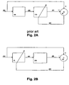
- Fig. 2A shows a schematic diagram indicating a known adaptive post-equalization setup, wherein an input data signal first passes a channel 100 and thereafter an adaptive post-equalizer 110.
- the adaptive post-equalizer feedback loop comprising the post-equalizer 110 and a subtraction circuit 90 does not include the channel 100.
- the output signal y[k] of the post-equalizer 110 is subtracted in the subtraction circuit 90 from the input data signal d[k] to thereby obtain an error signal or value e[k] used to control the adaptive post-equalizer 110.
- the input data signal or vector d[k] first passes the channel 100 which may be characterized by a transfer characteristic or vector.
- the output signal x[k] of the channel 100 is multiplied with the adaptive filter characteristic or vector of the post-equalizer 110.
- the resulting scalar value y[k] is subtracted from the input sample d[k], and the obtained error value e[k] is used to update the filter coefficients of the adaptive post-equalizer 110 for the next input samples. It is thus not necessary to know the channel transfer characteristic or vector explicitly, because the input data x[k] of the post-equalizer 110 automatically contains the channel information. Thus only one unknown value, i.e. the optimal coefficient vector must be determined.
- the equalizer is put in front of the non-ideal analog filters or channel and hence includes the analog filters or channel in its feedback loop. Therefore, the calculation of the optimal coefficient vector is based on two unknown variables or vectors, the analog filter transfer characteristic or vector and the optimal coefficient set of the adaptive pre-equalizer.
- Fig. 2B shows a corresponding adaptive pre-equalization setup which is based on the preferred embodiment shown in Fig. 1.
- the adaptive pre-equalizer 15 generates an input signal x[k] for the transmitter circuitry 200, wherein the output signal y[k] of the transmitter circuitry 200 is supplied to a subtractor or comparison circuitry 130 to which the input data signal d[k] is also supplied in order to obtain the error value e[k] based on which the pre-equalizer 15 is controlled.
- w [k] denotes the coefficient or weight vector of the pre-equalizer 15
- h [k] denotes the transfer vector of the transmission circuitry 200.
- the error value e[k] can be obtained based on following equation.
- the above equation (4) with its two unknown vectors can be solved based on an approximation and a single adaptation processing.
- the approximation can be performed for a gradient vector of the error value e[k].
- a least mean square (LMS) gradient vector can be determined.
- the starting point for the determination of the gradient approximation is the above equation (4).
- Fig. 3 shows an implementation example of the envelope error detection circuitry 70 in Fig. 1 based on the adaptive pre-equalization setup scheme of Fig. 2B. It is noted that in Fig. 3, the envelope measurement circuit 60 and the analog/digital converter 65 have been omitted for reasons of simplicity. Thus, the output value y[k] of the transmitter circuitry 200 corresponds to the digitized output value of the analog/digital converter 65.
- the output signal y[k] is supplied to a subtraction circuit 71 which generates the error value e[k].
- This error value e[k] is supplied to an adaptation circuit 72 arranged to determine an updated or new coefficient vector w [k + 1] for controlling the pre-equalizer 15.
- an approximation circuit 73 is provided for approximating the transfer characteristic or transfer vector h [k] of the transmitter circuitry 200. Accordingly, the output signal of the approximation circuit 73 corresponds to the above signal vector x ⁇ [k]. In view of the fact that the transfer vector h [k] is approximated in the approximation circuit 73, only one unknown variable has to be determined in the adaptation circuit 72.
- the signal vector x ⁇ [k] can be obtained by implementing a copy of the analog filter characteristic of the transmitter circuitry 200 in the approximation circuit 73. However, this would also require an identification process of this analog filter characteristic.
- the approximation circuit 73 may be adapted to implement the filter characteristic of the transmitter circuitry 200 as a simple delay block or function. Then, the required delay value corresponds to the analog filter delay ⁇ , i.e. the position of the maximum filter peak of the analog filter characteristic of the transmitter circuitry 200. This maximum peak can then be replaced by a value "1" in the transfer vector h [k], while the other vector components can be set to "0".
- FIR Finite Impulse Response
- Fig. 4 shows a more general flow diagram of the steps of the above adaptive pre-equalization scheme according to the preferred embodiment.
- step S101 a difference between the output signal y[k] of the equalized circuitry, i.e. the transmission circuitry 200, and the input signal d[k] of the equalizing function of the pre-equalizer 15 is determined.
- This difference corresponds to the error value e[k] and may be based on a comparison of the signal envelopes as explained earlier. However, any other signal parameter can be used for obtaining the difference.
- step S102 the transmission characteristic of the equalized circuitry is approximated.
- any approximation can be applied so as to derive one of the two unknown variables in equation (4).
- the input signal of the equalizing function is assessed with the approximated transmission characteristic (step S103).
- a gradient of the difference is approximated e.g. based on equation (8) (step S104). Having derived the gradient of the difference, the control values or coefficients of the pre-equalizing function are updated in step S105 based on the approximated gradient.
- the present invention provides a proposal for an adaptive pre-equalization approach which may be used e.g. for an analog filter characteristic of a transmitter circuitry or any other signal processing circuitry.
- the equalization is based on an approximation, e.g. an LMS approximation, and does not require a system identification process with respect to the analog filter characteristic, but approximates this characteristic by a simple delay block.
- an approximation e.g. an LMS approximation
- the invention gives the freedom to accept or promote tighter specifications with respect to the magnitude of the error value or vector in future standards. Furthermore, multipath delay spread tolerance can be improved by reducing intersymbol interference (ISI) which results from group delay equalization.
- ISI intersymbol interference
- the proposed adaptive low-complexity solution suites very well to volume production needs allowing larger tolerances for specifications. This may lead to an improved production yield.
- the present invention is not restricted to the preferred embodiment described above but can be used in any signal processing circuitry for reducing signal distortions.
- the comparison can be performed for any signal parameter suitable to obtain a difference caused by distortions of the signal processing circuitry.
- the control values for controlling the pre-equalizer may be obtained by any suitable approximation for obtaining a gradient of the difference value or error value.
- the pre-equalization may be adapted for use in heterodyne architectures or direct conversion architectures. It may as well be used for compensating amplitude imperfections, e.g. in-phase (1) and quadrature phase (Q) amplitude imperfections, for direct conversion architectures.
- the preferred embodiments may thus vary within the scope of the attached claims.
Landscapes
- Engineering & Computer Science (AREA)
- Computer Networks & Wireless Communication (AREA)
- Signal Processing (AREA)
- Power Engineering (AREA)
- Cable Transmission Systems, Equalization Of Radio And Reduction Of Echo (AREA)
- Filters That Use Time-Delay Elements (AREA)
- Transmitters (AREA)
- Organic Low-Molecular-Weight Compounds And Preparation Thereof (AREA)
- Amplifiers (AREA)
- Dc Digital Transmission (AREA)
Claims (12)
- Vorverzerrungsverfahren für eine Übertragungskennlinie eines Signalverarbeitungsschaltkreises (200), wobei das Verfahren die Schritte umfasst:a) Erhalten einer Differenz zwischen einem Ausgabesignal, des Signalverarbeitungsschaltkreises (200) und einem Eingabesignal einer Vorverzerrungsfunktion (15), wobei das Eingangssignal durch die Vorverzerrungsfunktion (15) gefiltert wird und das Ausgabesignal der Vorverzerrungsfunktion (15) eine Eingabe für den Signalverarbeitungsschaltkreis (200) ist;b) Berechnen einer Näherung des Gradienten des Erwartungswerts des Quadrats der Differenz basierend auf der erhaltenen Differenz und einer Näherung der Übertragungskennlinie; undc) Aktualisieren von Steuerwerten der Vorverzerrungsfunktion (15) basierend auf dem genäherten Gradienten,d) wobei die Übertragungskennlinie als eine Verzögerungsfunktion angenähert wird.
- Verfahren gemäß Anspruch 1, wobei der Gradientennäherungsschritt den Schritt umfasst Berechnen einer Näherung eines "Least Mean Square"-Gradientenvektors der Differenz umfasst.
- Verfahren gemäß Anspruch 2, wobei der Gradientenvektor aus einer partiellen Differenzialgleichung einer Systemkostenfunktion berechnet wird.
- Verfahren gemäß einem der vorhergehenden Ansprüche, wobei das Eingangssignal ein digitales Signal ist und das Ausgangssignal ein analoges Signal ist.
- Verfahren gemäß einem der vorhergehenden Ansprüche, wobei die Steuerwerte Koeffizienten eines adaptiven, digitalen Filters sind.
- Verfahren gemäß einem der vorhergehenden Ansprüche, wobei die Verzögerung der Verzögerungsfunktion der Position des maximalen analogen Filterspitzenwerts der Übertragungskennlinie entspricht.
- Verfahren gemäß Anspruch 6, wobei der Gradientenvektor unter Verwendung der folgenden Gleichung berechnet wird:

wobei∇{E} den Gradientenvektor bezeichnet,e[k] die erhaltene Differenz bezeichnet, undd[k - τ] eine Vektordarstellung des Eingabesignals bezeichnet, bewertet durch die Verzögerungsnäherung der Übertragungskennlinie. - Verfahren gemäß Anspruch 7, wobei Filterkoeffizienten in dem Aktualisierungsschritt basierend auf der folgenden Gleichung aktualisiert werden:

wobeiw[k + 1] eine Vektordarstellung der aktualisierten Koeffizienten bezeichnet,w[k] eine Vektordarstellung der aktuellen Filterkoeffizienten bezeichnet, undµ einen vorbestimmten Proportionalitätsfaktor bezeichnet. - Vorrichtung zum Vorverzerren einer Übertragungskennlinie eines Signalsverarbeitungsschaltkreises (200), wobei die Vorrichtung umfasst:a) Vergleichsmittel (71) zum Erhalten einer Differenz zwischen einem Eingabesignal des Signalverarbeitungsschaltkreises (200) und einem Eingabesignal eines Vorverzerrungsmittels (15), wobei das Eingabesignal durch die Vorverzerrungsmittel (15) gefiltert wird und das Ausgabesignal der Vorverzerrungsmittel (15) in den Signalverarbeitungsschaltkreis (200) eingegeben wird;b) Näherungsmittel (72, 73) zum Berechnen einer Näherung des Gradienten des Erwartungswerts des Quadrats der Differenz basierend auf der erhaltenen Differenz und einer Näherung der Übertragungskennlinie; undc) Aktualisierungsmittel (72) zum Erhalten von Steuerwerten, die in die Vorverzerrungsmitteln (15) eingegeben werden, basierend auf dem genäherten Gradienten;d) wobei die Näherungsmittel (72, 73) eingerichtet sind, die Übertragungskennlinie als eine Verzögerungsfunktion (73) anzunähern.
- Vorrichtung gemäß Anspruch 9, wobei die Näherungsmittel (72, 73) eingerichtet sind, den Gradienten unter Verwendung einer "Least Mean Square"-Näherungsfunktion zu nähern.
- Vorrichtung gemäß einen der vorhergehenden Ansprüchen 9 oder 10, wobei der Signalverarbeitungsschaltkreis eine Direktumsetzungs- oder Heterodyn-Senderarchitektur (200) besitzt.
- Vorrichtung gemäß einem der Ansprüche 9 bis 11, wobei die Vorrichtung digitale Vorverzerrungsmittel (15) umfasst.
Applications Claiming Priority (1)
| Application Number | Priority Date | Filing Date | Title |
|---|---|---|---|
| PCT/IB2002/002775 WO2004008707A1 (en) | 2002-07-15 | 2002-07-15 | Adaptive pre-equalization method and apparatus |
Publications (2)
| Publication Number | Publication Date |
|---|---|
| EP1523838A1 EP1523838A1 (de) | 2005-04-20 |
| EP1523838B1 true EP1523838B1 (de) | 2007-06-13 |
Family
ID=30011698
Family Applications (1)
| Application Number | Title | Priority Date | Filing Date |
|---|---|---|---|
| EP02745715A Expired - Lifetime EP1523838B1 (de) | 2002-07-15 | 2002-07-15 | Methode und apparat für adaptive vorverzerrung |
Country Status (12)
| Country | Link |
|---|---|
| US (1) | US20060056327A1 (de) |
| EP (1) | EP1523838B1 (de) |
| JP (1) | JP2005538578A (de) |
| KR (1) | KR100668125B1 (de) |
| CN (1) | CN100514954C (de) |
| AT (1) | ATE364950T1 (de) |
| AU (1) | AU2002317424A1 (de) |
| DE (1) | DE60220726T2 (de) |
| ES (1) | ES2287294T3 (de) |
| NO (1) | NO20045325L (de) |
| TW (1) | TWI291291B (de) |
| WO (1) | WO2004008707A1 (de) |
Families Citing this family (55)
| Publication number | Priority date | Publication date | Assignee | Title |
|---|---|---|---|---|
| JP4550639B2 (ja) * | 2005-03-29 | 2010-09-22 | 株式会社東芝 | 線形歪み検出器及び線形歪み補償器 |
| DE602005010592D1 (de) * | 2005-11-15 | 2008-12-04 | Alcatel Lucent | Verfahren zur Übertragung von Kanalqualitätsinformationen in einem Multiträger-Funkkommunikationssystem und entsprechende Mobilstation und Basisstation |
| US8873585B2 (en) | 2006-12-19 | 2014-10-28 | Corning Optical Communications Wireless Ltd | Distributed antenna system for MIMO technologies |
| US8902365B2 (en) * | 2007-03-14 | 2014-12-02 | Lance Greggain | Interference avoidance in a television receiver |
| US9083940B2 (en) * | 2007-03-14 | 2015-07-14 | Steve Selby | Automatic gain control system |
| US8358937B2 (en) * | 2007-05-24 | 2013-01-22 | Applied Optoelectronics, Inc. | Systems and methods for reducing clipping in multichannel modulated optical systems |
| US8165475B2 (en) * | 2007-05-24 | 2012-04-24 | Applied Optoelectronics | Systems and methods for reducing clipping in multichannel modulated optical systems |
| WO2009081376A2 (en) * | 2007-12-20 | 2009-07-02 | Mobileaccess Networks Ltd. | Extending outdoor location based services and applications into enclosed areas |
| US8165474B2 (en) * | 2008-03-21 | 2012-04-24 | Applied Optoelectronics, Inc. | Reducing cross modulation in multichannel modulated optical systems with anti-clipping |
| US8730878B2 (en) | 2008-08-20 | 2014-05-20 | Qualcomm Incorporated | Power and resource efficient APPDU based approach with scheduled block ACKS for WLAN |
| EP2344915A4 (de) | 2008-10-09 | 2015-01-21 | Corning Cable Sys Llc | Faseroptischer anschluss mit adaptertafel, die sowohl eingangs- als auch ausgangsfasern von einem optischen teiler unterstützt |
| US9673904B2 (en) | 2009-02-03 | 2017-06-06 | Corning Optical Communications LLC | Optical fiber-based distributed antenna systems, components, and related methods for calibration thereof |
| WO2010091004A1 (en) | 2009-02-03 | 2010-08-12 | Corning Cable Systems Llc | Optical fiber-based distributed antenna systems, components, and related methods for calibration thereof |
| AU2010210766A1 (en) | 2009-02-03 | 2011-09-15 | Corning Cable Systems Llc | Optical fiber-based distributed antenna systems, components, and related methods for monitoring and configuring thereof |
| US9590733B2 (en) | 2009-07-24 | 2017-03-07 | Corning Optical Communications LLC | Location tracking using fiber optic array cables and related systems and methods |
| KR101061137B1 (ko) * | 2009-08-18 | 2011-08-31 | 연세대학교 산학협력단 | 고속 적응형 등화기 및 그것의 제어 방법 |
| US8280259B2 (en) | 2009-11-13 | 2012-10-02 | Corning Cable Systems Llc | Radio-over-fiber (RoF) system for protocol-independent wired and/or wireless communication |
| US8275265B2 (en) | 2010-02-15 | 2012-09-25 | Corning Cable Systems Llc | Dynamic cell bonding (DCB) for radio-over-fiber (RoF)-based networks and communication systems and related methods |
| CN102845001B (zh) | 2010-03-31 | 2016-07-06 | 康宁光缆系统有限责任公司 | 基于光纤的分布式通信组件及系统中的定位服务以及相关方法 |
| US8570914B2 (en) | 2010-08-09 | 2013-10-29 | Corning Cable Systems Llc | Apparatuses, systems, and methods for determining location of a mobile device(s) in a distributed antenna system(s) |
| US9252874B2 (en) | 2010-10-13 | 2016-02-02 | Ccs Technology, Inc | Power management for remote antenna units in distributed antenna systems |
| US9547145B2 (en) | 2010-10-19 | 2017-01-17 | Corning Optical Communications LLC | Local convergence point for multiple dwelling unit fiber optic distribution network |
| CN103609146B (zh) | 2011-04-29 | 2017-05-31 | 康宁光缆系统有限责任公司 | 用于增加分布式天线系统中的射频(rf)功率的系统、方法和装置 |
| WO2012148938A1 (en) | 2011-04-29 | 2012-11-01 | Corning Cable Systems Llc | Determining propagation delay of communications in distributed antenna systems, and related components, systems and methods |
| US9219546B2 (en) | 2011-12-12 | 2015-12-22 | Corning Optical Communications LLC | Extremely high frequency (EHF) distributed antenna systems, and related components and methods |
| US10110307B2 (en) | 2012-03-02 | 2018-10-23 | Corning Optical Communications LLC | Optical network units (ONUs) for high bandwidth connectivity, and related components and methods |
| US8891974B2 (en) | 2012-03-30 | 2014-11-18 | Applied Optoelectronics, Inc. | Distortion compensation circuit including tunable phase path |
| EP2832012A1 (de) | 2012-03-30 | 2015-02-04 | Corning Optical Communications LLC | Reduzierung ortsabhängiger interferenzen in verteilten antennensystemen in einer mimo-konfiguration sowie entsprechende komponenten, systeme und verfahren |
| US9781553B2 (en) | 2012-04-24 | 2017-10-03 | Corning Optical Communications LLC | Location based services in a distributed communication system, and related components and methods |
| WO2013162988A1 (en) | 2012-04-25 | 2013-10-31 | Corning Cable Systems Llc | Distributed antenna system architectures |
| CN103378870B (zh) * | 2012-04-26 | 2015-08-05 | 启碁科技股份有限公司 | 通讯装置与射频均衡器 |
| EP2883416A1 (de) | 2012-08-07 | 2015-06-17 | Corning Optical Communications Wireless Ltd. | Verteilung von zeitlich gemultiplexten (tdm) management-diensten in einem verteilten antennensystem sowie entsprechende komponenten, systeme und verfahren |
| US9455784B2 (en) | 2012-10-31 | 2016-09-27 | Corning Optical Communications Wireless Ltd | Deployable wireless infrastructures and methods of deploying wireless infrastructures |
| EP2926466A1 (de) | 2012-11-29 | 2015-10-07 | Corning Optical Communications LLC | Hybride intrazell-/interzell-ferneinheiten-antennenbindung in verteilten mimo-antennensystemen |
| US9647758B2 (en) | 2012-11-30 | 2017-05-09 | Corning Optical Communications Wireless Ltd | Cabling connectivity monitoring and verification |
| US9158864B2 (en) | 2012-12-21 | 2015-10-13 | Corning Optical Communications Wireless Ltd | Systems, methods, and devices for documenting a location of installed equipment |
| CN105452951B (zh) | 2013-06-12 | 2018-10-19 | 康宁光电通信无线公司 | 电压控制式光学定向耦合器 |
| WO2014199380A1 (en) | 2013-06-12 | 2014-12-18 | Corning Optical Communications Wireless, Ltd. | Time-division duplexing (tdd) in distributed communications systems, including distributed antenna systems (dass) |
| US9247543B2 (en) | 2013-07-23 | 2016-01-26 | Corning Optical Communications Wireless Ltd | Monitoring non-supported wireless spectrum within coverage areas of distributed antenna systems (DASs) |
| US9661781B2 (en) | 2013-07-31 | 2017-05-23 | Corning Optical Communications Wireless Ltd | Remote units for distributed communication systems and related installation methods and apparatuses |
| US9385810B2 (en) | 2013-09-30 | 2016-07-05 | Corning Optical Communications Wireless Ltd | Connection mapping in distributed communication systems |
| US9178635B2 (en) | 2014-01-03 | 2015-11-03 | Corning Optical Communications Wireless Ltd | Separation of communication signal sub-bands in distributed antenna systems (DASs) to reduce interference |
| US9775123B2 (en) | 2014-03-28 | 2017-09-26 | Corning Optical Communications Wireless Ltd. | Individualized gain control of uplink paths in remote units in a distributed antenna system (DAS) based on individual remote unit contribution to combined uplink power |
| US9357551B2 (en) | 2014-05-30 | 2016-05-31 | Corning Optical Communications Wireless Ltd | Systems and methods for simultaneous sampling of serial digital data streams from multiple analog-to-digital converters (ADCS), including in distributed antenna systems |
| US9525472B2 (en) | 2014-07-30 | 2016-12-20 | Corning Incorporated | Reducing location-dependent destructive interference in distributed antenna systems (DASS) operating in multiple-input, multiple-output (MIMO) configuration, and related components, systems, and methods |
| US9730228B2 (en) | 2014-08-29 | 2017-08-08 | Corning Optical Communications Wireless Ltd | Individualized gain control of remote uplink band paths in a remote unit in a distributed antenna system (DAS), based on combined uplink power level in the remote unit |
| US9602210B2 (en) | 2014-09-24 | 2017-03-21 | Corning Optical Communications Wireless Ltd | Flexible head-end chassis supporting automatic identification and interconnection of radio interface modules and optical interface modules in an optical fiber-based distributed antenna system (DAS) |
| US9420542B2 (en) | 2014-09-25 | 2016-08-16 | Corning Optical Communications Wireless Ltd | System-wide uplink band gain control in a distributed antenna system (DAS), based on per band gain control of remote uplink paths in remote units |
| US9729267B2 (en) | 2014-12-11 | 2017-08-08 | Corning Optical Communications Wireless Ltd | Multiplexing two separate optical links with the same wavelength using asymmetric combining and splitting |
| US20160249365A1 (en) | 2015-02-19 | 2016-08-25 | Corning Optical Communications Wireless Ltd. | Offsetting unwanted downlink interference signals in an uplink path in a distributed antenna system (das) |
| US9681313B2 (en) | 2015-04-15 | 2017-06-13 | Corning Optical Communications Wireless Ltd | Optimizing remote antenna unit performance using an alternative data channel |
| US9948349B2 (en) | 2015-07-17 | 2018-04-17 | Corning Optical Communications Wireless Ltd | IOT automation and data collection system |
| US10560214B2 (en) | 2015-09-28 | 2020-02-11 | Corning Optical Communications LLC | Downlink and uplink communication path switching in a time-division duplex (TDD) distributed antenna system (DAS) |
| US9648580B1 (en) | 2016-03-23 | 2017-05-09 | Corning Optical Communications Wireless Ltd | Identifying remote units in a wireless distribution system (WDS) based on assigned unique temporal delay patterns |
| US10236924B2 (en) | 2016-03-31 | 2019-03-19 | Corning Optical Communications Wireless Ltd | Reducing out-of-channel noise in a wireless distribution system (WDS) |
Family Cites Families (6)
| Publication number | Priority date | Publication date | Assignee | Title |
|---|---|---|---|---|
| WO1998059471A2 (en) * | 1997-06-20 | 1998-12-30 | Ericsson Inc. | Method and apparatus for digital compensation of radio distortion in a wireless communication system |
| US6285412B1 (en) * | 1997-07-23 | 2001-09-04 | Harris Corporation | Adaptive pre-equalization apparatus for correcting linear distortion of a non-ideal data transmission system |
| US6054896A (en) * | 1998-12-17 | 2000-04-25 | Datum Telegraphic Inc. | Controller and associated methods for a linc linear power amplifier |
| US6834109B1 (en) * | 1999-11-11 | 2004-12-21 | Tokyo Electron Limited | Method and apparatus for mitigation of disturbers in communication systems |
| US7015751B2 (en) * | 2001-06-28 | 2006-03-21 | Simon Fraser University | Decorrelated power amplifier linearizers |
| US6794936B2 (en) * | 2001-07-03 | 2004-09-21 | Lucent Technologies Inc. | Equalizer system and method for predistortion |
-
2002
- 2002-07-15 CN CNB028293231A patent/CN100514954C/zh not_active Expired - Fee Related
- 2002-07-15 AU AU2002317424A patent/AU2002317424A1/en not_active Abandoned
- 2002-07-15 ES ES02745715T patent/ES2287294T3/es not_active Expired - Lifetime
- 2002-07-15 DE DE60220726T patent/DE60220726T2/de not_active Expired - Fee Related
- 2002-07-15 JP JP2004520921A patent/JP2005538578A/ja active Pending
- 2002-07-15 US US10/520,383 patent/US20060056327A1/en not_active Abandoned
- 2002-07-15 AT AT02745715T patent/ATE364950T1/de not_active IP Right Cessation
- 2002-07-15 WO PCT/IB2002/002775 patent/WO2004008707A1/en not_active Ceased
- 2002-07-15 KR KR1020057000619A patent/KR100668125B1/ko not_active Expired - Fee Related
- 2002-07-15 EP EP02745715A patent/EP1523838B1/de not_active Expired - Lifetime
-
2003
- 2003-07-09 TW TW092118662A patent/TWI291291B/zh not_active IP Right Cessation
-
2004
- 2004-12-03 NO NO20045325A patent/NO20045325L/no not_active Application Discontinuation
Non-Patent Citations (1)
| Title |
|---|
| WIDROW B.; STEARNS S. D.: "Adaptive Signal Processing (pp. 232-244)", 1985, PRENTICE HALL, LONDON, XP002381954 * |
Also Published As
| Publication number | Publication date |
|---|---|
| KR100668125B1 (ko) | 2007-01-16 |
| KR20050019857A (ko) | 2005-03-03 |
| WO2004008707A1 (en) | 2004-01-22 |
| EP1523838A1 (de) | 2005-04-20 |
| AU2002317424A1 (en) | 2004-02-02 |
| TWI291291B (en) | 2007-12-11 |
| NO20045325L (no) | 2005-02-14 |
| CN100514954C (zh) | 2009-07-15 |
| CN1656766A (zh) | 2005-08-17 |
| TW200403932A (en) | 2004-03-01 |
| JP2005538578A (ja) | 2005-12-15 |
| US20060056327A1 (en) | 2006-03-16 |
| DE60220726D1 (de) | 2007-07-26 |
| ATE364950T1 (de) | 2007-07-15 |
| ES2287294T3 (es) | 2007-12-16 |
| DE60220726T2 (de) | 2008-02-21 |
Similar Documents
| Publication | Publication Date | Title |
|---|---|---|
| US20060056327A1 (en) | Adaptive pre-equalization method and apparatus | |
| US7200180B2 (en) | Data transceiver with filtering and precoding | |
| US6205170B1 (en) | Transmission/reception unit with bidirectional equalization | |
| US7512191B2 (en) | Method and apparatus for implementing a channel correction in a digital data link | |
| EP0467412A2 (de) | Leitungsentzerrer für digitale Signale | |
| EP2399353B1 (de) | Entzerrer für ein optisches übertragungssystem | |
| US6151358A (en) | Method and apparatus, and computer program for producing filter coefficients for equalizers | |
| EP1157514B1 (de) | Kalman-entzerrung in mehrträgerempfängern | |
| US7627055B2 (en) | Error adjustment in direct conversion architectures | |
| AU2015321409A1 (en) | Linear equalization for use in low latency high speed communication systems | |
| US20050201483A1 (en) | Error adjustment for multi-antenna transmitter | |
| CN1885984B (zh) | 通信装置以及通信方法 | |
| US10270617B2 (en) | Method and apparatus for high speed equalization of data packet received from bus topology network | |
| US6047024A (en) | Device for equalizing channel-distorted signals | |
| EP1595378B1 (de) | Verfahren und vorrichtung zur erzeugung von entzerrungskoeffizienten in einem ofdm-system | |
| JPH06500914A (ja) | 信号点、等化器利得などを調整する装置および方法 | |
| Tu | Optimum MMSE equalization for staggered modulation | |
| US20070223570A1 (en) | Distortion Compensating Equalizer | |
| JP2002280941A (ja) | 適応等化器、受信装置およびタップ係数算出方法 | |
| US7042962B2 (en) | LMS-based channel estimation | |
| US8611451B1 (en) | Precoder coefficient optimization method and apparatus for communications systems | |
| RU2292659C2 (ru) | Способ и устройство адаптивной предварительной коррекции | |
| Lopez-Estraviz et al. | EM based frequency-dependent transmit/receive IQ imbalance estimation and compensation in OFDM-based transceivers | |
| Sonal | Machine learning for PAPR distortion reduction in OFDM systems | |
| CN116232419B (zh) | 一种非线性卫星信道均衡方法及系统 |
Legal Events
| Date | Code | Title | Description |
|---|---|---|---|
| PUAI | Public reference made under article 153(3) epc to a published international application that has entered the european phase |
Free format text: ORIGINAL CODE: 0009012 |
|
| 17P | Request for examination filed |
Effective date: 20050215 |
|
| AK | Designated contracting states |
Kind code of ref document: A1 Designated state(s): AT BE BG CH CY CZ DE DK EE ES FI FR GB GR IE IT LI LU MC NL PT SE SK TR |
|
| AX | Request for extension of the european patent |
Extension state: AL LT LV MK RO SI |
|
| 17Q | First examination report despatched |
Effective date: 20050512 |
|
| DAX | Request for extension of the european patent (deleted) | ||
| GRAP | Despatch of communication of intention to grant a patent |
Free format text: ORIGINAL CODE: EPIDOSNIGR1 |
|
| GRAS | Grant fee paid |
Free format text: ORIGINAL CODE: EPIDOSNIGR3 |
|
| 17Q | First examination report despatched |
Effective date: 20050512 |
|
| GRAA | (expected) grant |
Free format text: ORIGINAL CODE: 0009210 |
|
| AK | Designated contracting states |
Kind code of ref document: B1 Designated state(s): AT BE BG CH CY CZ DE DK EE ES FI FR GB GR IE IT LI LU MC NL PT SE SK TR |
|
| PG25 | Lapsed in a contracting state [announced via postgrant information from national office to epo] |
Ref country code: LI Free format text: LAPSE BECAUSE OF FAILURE TO SUBMIT A TRANSLATION OF THE DESCRIPTION OR TO PAY THE FEE WITHIN THE PRESCRIBED TIME-LIMIT Effective date: 20070613 Ref country code: CH Free format text: LAPSE BECAUSE OF FAILURE TO SUBMIT A TRANSLATION OF THE DESCRIPTION OR TO PAY THE FEE WITHIN THE PRESCRIBED TIME-LIMIT Effective date: 20070613 |
|
| REG | Reference to a national code |
Ref country code: GB Ref legal event code: FG4D |
|
| REG | Reference to a national code |
Ref country code: CH Ref legal event code: EP |
|
| REG | Reference to a national code |
Ref country code: IE Ref legal event code: FG4D |
|
| REF | Corresponds to: |
Ref document number: 60220726 Country of ref document: DE Date of ref document: 20070726 Kind code of ref document: P |
|
| PG25 | Lapsed in a contracting state [announced via postgrant information from national office to epo] |
Ref country code: SE Free format text: LAPSE BECAUSE OF FAILURE TO SUBMIT A TRANSLATION OF THE DESCRIPTION OR TO PAY THE FEE WITHIN THE PRESCRIBED TIME-LIMIT Effective date: 20070913 |
|
| ET | Fr: translation filed | ||
| PG25 | Lapsed in a contracting state [announced via postgrant information from national office to epo] |
Ref country code: AT Free format text: LAPSE BECAUSE OF FAILURE TO SUBMIT A TRANSLATION OF THE DESCRIPTION OR TO PAY THE FEE WITHIN THE PRESCRIBED TIME-LIMIT Effective date: 20070613 |
|
| NLV1 | Nl: lapsed or annulled due to failure to fulfill the requirements of art. 29p and 29m of the patents act | ||
| REG | Reference to a national code |
Ref country code: ES Ref legal event code: FG2A Ref document number: 2287294 Country of ref document: ES Kind code of ref document: T3 |
|
| REG | Reference to a national code |
Ref country code: CH Ref legal event code: PL |
|
| PG25 | Lapsed in a contracting state [announced via postgrant information from national office to epo] |
Ref country code: BE Free format text: LAPSE BECAUSE OF FAILURE TO SUBMIT A TRANSLATION OF THE DESCRIPTION OR TO PAY THE FEE WITHIN THE PRESCRIBED TIME-LIMIT Effective date: 20070613 |
|
| PG25 | Lapsed in a contracting state [announced via postgrant information from national office to epo] |
Ref country code: NL Free format text: LAPSE BECAUSE OF FAILURE TO SUBMIT A TRANSLATION OF THE DESCRIPTION OR TO PAY THE FEE WITHIN THE PRESCRIBED TIME-LIMIT Effective date: 20070613 Ref country code: PT Free format text: LAPSE BECAUSE OF FAILURE TO SUBMIT A TRANSLATION OF THE DESCRIPTION OR TO PAY THE FEE WITHIN THE PRESCRIBED TIME-LIMIT Effective date: 20071113 Ref country code: BG Free format text: LAPSE BECAUSE OF FAILURE TO SUBMIT A TRANSLATION OF THE DESCRIPTION OR TO PAY THE FEE WITHIN THE PRESCRIBED TIME-LIMIT Effective date: 20070913 Ref country code: CZ Free format text: LAPSE BECAUSE OF FAILURE TO SUBMIT A TRANSLATION OF THE DESCRIPTION OR TO PAY THE FEE WITHIN THE PRESCRIBED TIME-LIMIT Effective date: 20070613 |
|
| PG25 | Lapsed in a contracting state [announced via postgrant information from national office to epo] |
Ref country code: SK Free format text: LAPSE BECAUSE OF FAILURE TO SUBMIT A TRANSLATION OF THE DESCRIPTION OR TO PAY THE FEE WITHIN THE PRESCRIBED TIME-LIMIT Effective date: 20070613 |
|
| PLBE | No opposition filed within time limit |
Free format text: ORIGINAL CODE: 0009261 |
|
| STAA | Information on the status of an ep patent application or granted ep patent |
Free format text: STATUS: NO OPPOSITION FILED WITHIN TIME LIMIT |
|
| PG25 | Lapsed in a contracting state [announced via postgrant information from national office to epo] |
Ref country code: GR Free format text: LAPSE BECAUSE OF FAILURE TO SUBMIT A TRANSLATION OF THE DESCRIPTION OR TO PAY THE FEE WITHIN THE PRESCRIBED TIME-LIMIT Effective date: 20070914 Ref country code: MC Free format text: LAPSE BECAUSE OF NON-PAYMENT OF DUE FEES Effective date: 20070731 Ref country code: DK Free format text: LAPSE BECAUSE OF FAILURE TO SUBMIT A TRANSLATION OF THE DESCRIPTION OR TO PAY THE FEE WITHIN THE PRESCRIBED TIME-LIMIT Effective date: 20070613 |
|
| 26N | No opposition filed |
Effective date: 20080314 |
|
| PG25 | Lapsed in a contracting state [announced via postgrant information from national office to epo] |
Ref country code: IE Free format text: LAPSE BECAUSE OF NON-PAYMENT OF DUE FEES Effective date: 20070716 |
|
| PG25 | Lapsed in a contracting state [announced via postgrant information from national office to epo] |
Ref country code: EE Free format text: LAPSE BECAUSE OF FAILURE TO SUBMIT A TRANSLATION OF THE DESCRIPTION OR TO PAY THE FEE WITHIN THE PRESCRIBED TIME-LIMIT Effective date: 20070613 |
|
| PG25 | Lapsed in a contracting state [announced via postgrant information from national office to epo] |
Ref country code: FI Free format text: LAPSE BECAUSE OF FAILURE TO SUBMIT A TRANSLATION OF THE DESCRIPTION OR TO PAY THE FEE WITHIN THE PRESCRIBED TIME-LIMIT Effective date: 20070613 |
|
| PG25 | Lapsed in a contracting state [announced via postgrant information from national office to epo] |
Ref country code: CY Free format text: LAPSE BECAUSE OF FAILURE TO SUBMIT A TRANSLATION OF THE DESCRIPTION OR TO PAY THE FEE WITHIN THE PRESCRIBED TIME-LIMIT Effective date: 20070613 |
|
| PG25 | Lapsed in a contracting state [announced via postgrant information from national office to epo] |
Ref country code: LU Free format text: LAPSE BECAUSE OF NON-PAYMENT OF DUE FEES Effective date: 20070715 |
|
| PG25 | Lapsed in a contracting state [announced via postgrant information from national office to epo] |
Ref country code: TR Free format text: LAPSE BECAUSE OF FAILURE TO SUBMIT A TRANSLATION OF THE DESCRIPTION OR TO PAY THE FEE WITHIN THE PRESCRIBED TIME-LIMIT Effective date: 20070613 |
|
| PGFP | Annual fee paid to national office [announced via postgrant information from national office to epo] |
Ref country code: ES Payment date: 20090812 Year of fee payment: 8 Ref country code: FR Payment date: 20090710 Year of fee payment: 8 |
|
| PGFP | Annual fee paid to national office [announced via postgrant information from national office to epo] |
Ref country code: DE Payment date: 20090709 Year of fee payment: 8 Ref country code: GB Payment date: 20090715 Year of fee payment: 8 |
|
| PGFP | Annual fee paid to national office [announced via postgrant information from national office to epo] |
Ref country code: IT Payment date: 20090717 Year of fee payment: 8 |
|
| GBPC | Gb: european patent ceased through non-payment of renewal fee |
Effective date: 20100715 |
|
| REG | Reference to a national code |
Ref country code: FR Ref legal event code: ST Effective date: 20110331 |
|
| PG25 | Lapsed in a contracting state [announced via postgrant information from national office to epo] |
Ref country code: DE Free format text: LAPSE BECAUSE OF NON-PAYMENT OF DUE FEES Effective date: 20110201 |
|
| REG | Reference to a national code |
Ref country code: DE Ref legal event code: R119 Ref document number: 60220726 Country of ref document: DE Effective date: 20110201 |
|
| PG25 | Lapsed in a contracting state [announced via postgrant information from national office to epo] |
Ref country code: FR Free format text: LAPSE BECAUSE OF NON-PAYMENT OF DUE FEES Effective date: 20100802 Ref country code: IT Free format text: LAPSE BECAUSE OF NON-PAYMENT OF DUE FEES Effective date: 20100715 |
|
| PG25 | Lapsed in a contracting state [announced via postgrant information from national office to epo] |
Ref country code: GB Free format text: LAPSE BECAUSE OF NON-PAYMENT OF DUE FEES Effective date: 20100715 |
|
| REG | Reference to a national code |
Ref country code: ES Ref legal event code: FD2A Effective date: 20110818 |
|
| PG25 | Lapsed in a contracting state [announced via postgrant information from national office to epo] |
Ref country code: ES Free format text: LAPSE BECAUSE OF NON-PAYMENT OF DUE FEES Effective date: 20100716 |