EP1523738B1 - System und verfahren zur thermischen überwachung eines gebietes - Google Patents
System und verfahren zur thermischen überwachung eines gebietes Download PDFInfo
- Publication number
- EP1523738B1 EP1523738B1 EP02765325A EP02765325A EP1523738B1 EP 1523738 B1 EP1523738 B1 EP 1523738B1 EP 02765325 A EP02765325 A EP 02765325A EP 02765325 A EP02765325 A EP 02765325A EP 1523738 B1 EP1523738 B1 EP 1523738B1
- Authority
- EP
- European Patent Office
- Prior art keywords
- data
- apt
- previous
- central control
- control station
- Prior art date
- Legal status (The legal status is an assumption and is not a legal conclusion. Google has not performed a legal analysis and makes no representation as to the accuracy of the status listed.)
- Expired - Lifetime
Links
- 238000012544 monitoring process Methods 0.000 title claims abstract description 16
- 238000000034 method Methods 0.000 title claims description 18
- 238000012545 processing Methods 0.000 claims abstract description 37
- 230000007613 environmental effect Effects 0.000 claims abstract description 20
- 238000001514 detection method Methods 0.000 claims description 42
- 230000005540 biological transmission Effects 0.000 claims description 9
- 238000004458 analytical method Methods 0.000 claims description 8
- 230000006378 damage Effects 0.000 claims description 7
- 238000004891 communication Methods 0.000 claims description 5
- 230000002146 bilateral effect Effects 0.000 claims description 2
- 238000012986 modification Methods 0.000 claims description 2
- 230000004048 modification Effects 0.000 claims description 2
- 230000004913 activation Effects 0.000 claims 2
- 230000003044 adaptive effect Effects 0.000 claims 1
- 230000008033 biological extinction Effects 0.000 abstract 1
- 238000013507 mapping Methods 0.000 description 6
- 238000012806 monitoring device Methods 0.000 description 5
- 238000005516 engineering process Methods 0.000 description 4
- 230000008901 benefit Effects 0.000 description 3
- 238000011161 development Methods 0.000 description 3
- 239000011159 matrix material Substances 0.000 description 3
- 230000008569 process Effects 0.000 description 3
- 230000003595 spectral effect Effects 0.000 description 3
- 230000000007 visual effect Effects 0.000 description 3
- 208000031968 Cadaver Diseases 0.000 description 2
- 108010001267 Protein Subunits Proteins 0.000 description 2
- 230000000694 effects Effects 0.000 description 2
- 239000000835 fiber Substances 0.000 description 2
- 238000003384 imaging method Methods 0.000 description 2
- 239000000463 material Substances 0.000 description 2
- 238000005259 measurement Methods 0.000 description 2
- VNWKTOKETHGBQD-UHFFFAOYSA-N methane Chemical compound C VNWKTOKETHGBQD-UHFFFAOYSA-N 0.000 description 2
- 230000000877 morphologic effect Effects 0.000 description 2
- 230000005855 radiation Effects 0.000 description 2
- UTVKUFYOPJCDPE-UHFFFAOYSA-N 6-apt Chemical compound C1CCCC2=CC(CC(N)C)=CC=C21 UTVKUFYOPJCDPE-UHFFFAOYSA-N 0.000 description 1
- 206010057040 Temperature intolerance Diseases 0.000 description 1
- 238000010521 absorption reaction Methods 0.000 description 1
- 238000013019 agitation Methods 0.000 description 1
- 230000002547 anomalous effect Effects 0.000 description 1
- 239000003086 colorant Substances 0.000 description 1
- 238000001816 cooling Methods 0.000 description 1
- 238000012937 correction Methods 0.000 description 1
- 238000010586 diagram Methods 0.000 description 1
- 230000005670 electromagnetic radiation Effects 0.000 description 1
- 230000036541 health Effects 0.000 description 1
- 230000008543 heat sensitivity Effects 0.000 description 1
- 229910001416 lithium ion Inorganic materials 0.000 description 1
- 230000033001 locomotion Effects 0.000 description 1
- 238000012423 maintenance Methods 0.000 description 1
- 230000007257 malfunction Effects 0.000 description 1
- 230000003287 optical effect Effects 0.000 description 1
- 230000035945 sensitivity Effects 0.000 description 1
- PUZPDOWCWNUUKD-UHFFFAOYSA-M sodium fluoride Chemical compound [F-].[Na+] PUZPDOWCWNUUKD-UHFFFAOYSA-M 0.000 description 1
- 238000001228 spectrum Methods 0.000 description 1
- 230000007480 spreading Effects 0.000 description 1
- 230000006641 stabilisation Effects 0.000 description 1
- 230000003685 thermal hair damage Effects 0.000 description 1
- 238000012876 topography Methods 0.000 description 1
- 238000013519 translation Methods 0.000 description 1
- 238000012800 visualization Methods 0.000 description 1
- XLYOFNOQVPJJNP-UHFFFAOYSA-N water Substances O XLYOFNOQVPJJNP-UHFFFAOYSA-N 0.000 description 1
Images

Classifications
-
- G—PHYSICS
- G08—SIGNALLING
- G08B—SIGNALLING OR CALLING SYSTEMS; ORDER TELEGRAPHS; ALARM SYSTEMS
- G08B17/00—Fire alarms; Alarms responsive to explosion
- G08B17/005—Fire alarms; Alarms responsive to explosion for forest fires, e.g. detecting fires spread over a large or outdoors area
-
- F—MECHANICAL ENGINEERING; LIGHTING; HEATING; WEAPONS; BLASTING
- F24—HEATING; RANGES; VENTILATING
- F24S—SOLAR HEAT COLLECTORS; SOLAR HEAT SYSTEMS
- F24S25/00—Arrangement of stationary mountings or supports for solar heat collector modules
- F24S25/10—Arrangement of stationary mountings or supports for solar heat collector modules extending in directions away from a supporting surface
-
- G—PHYSICS
- G08—SIGNALLING
- G08B—SIGNALLING OR CALLING SYSTEMS; ORDER TELEGRAPHS; ALARM SYSTEMS
- G08B17/00—Fire alarms; Alarms responsive to explosion
- G08B17/12—Actuation by presence of radiation or particles, e.g. of infrared radiation or of ions
- G08B17/125—Actuation by presence of radiation or particles, e.g. of infrared radiation or of ions by using a video camera to detect fire or smoke
-
- Y—GENERAL TAGGING OF NEW TECHNOLOGICAL DEVELOPMENTS; GENERAL TAGGING OF CROSS-SECTIONAL TECHNOLOGIES SPANNING OVER SEVERAL SECTIONS OF THE IPC; TECHNICAL SUBJECTS COVERED BY FORMER USPC CROSS-REFERENCE ART COLLECTIONS [XRACs] AND DIGESTS
- Y02—TECHNOLOGIES OR APPLICATIONS FOR MITIGATION OR ADAPTATION AGAINST CLIMATE CHANGE
- Y02E—REDUCTION OF GREENHOUSE GAS [GHG] EMISSIONS, RELATED TO ENERGY GENERATION, TRANSMISSION OR DISTRIBUTION
- Y02E10/00—Energy generation through renewable energy sources
- Y02E10/40—Solar thermal energy, e.g. solar towers
- Y02E10/47—Mountings or tracking
Definitions
- the present invention relates to an environment monitoring system and to a related method.
- the invention relates to an integrated system for detecting critical thermal levels in the environment.
- the invention provides a system for detecting fires within wooded areas.
- the invention generally relates to a system for detecting critical thermal variations in any type of environment, and in particular in industrial facilities, buildings and so on.
- a temperature rise can lead to fires or, in fact, indicate the presence of flames.
- US 2002/0026431 discloses a fire detection system comprising surveillance satellites having fire detection means based on imaging equipment, surveillance aircraft or balloons also carrying said fire detection equipment, fire control headquarters in communication with said satellites and crafts and remote centers for helping the headquarters in the control and coordination of fire fighting resources.
- the remote centers are in voice communication with headquarters for full coordination.
- selected fire fighting resources can have video or infrared sensors for detecting fire.
- Control centers, satellites, surveillance crafts and fire fighting resources are also apt to update the headquarters with weather information.
- US 2002/0026431 also mentions that infrared sensing units can be located on towers communicating with headquarters or remote centers.
- US 2002/0026431 provides for a fire fighting system wherein multiple resources - and specifically satellites, crafts and eventually selected fire fighting resources - are used for detecting fire by imaging techniques and wherein local control centers and headquarters are used for detecting weather conditions and for coordinating such resources.
- the technical problems constituting the basis for the present invention is to provide an environment monitoring system and a related method that allow to improve the rapidity and effectiveness of operations aimed at limiting and/or containing damages in case of critical temperature rise and in particular of operations for extinguishing a fire event.
- the present invention also relates to a method according to claim 23.
- environment monitoring is to be construed in the broad sense, as referred to the monitoring of any kind of environment, in particular wooded areas, natural parks, agricultural areas, civil areas, military areas, industrial areas, specific facilities and/or buildings and/or areas delimited thereby, and so on.
- critical temperature variations indicates temperature variations apt to cause damages in the monitored environment, for instance variations that indicate the onset of a fire.
- the present invention provides some important advantages.
- the main advantage is that the integrated processing of locally acquired data with those known a priori and stored at the central control station level allows to optimise the time and quality of the operations aimed at limiting the consequent damage.
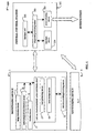
- an environment monitoring system according to the present invention, and in particular a system for territory thermal monitoring, is globally indicated as 100.
- This comprises first of all a plurality of monitoring devices distributed over the territory to be monitored, one of which is shown in greater detail in Figure 2 and is globally indicated as 1.
- the devices 1 will be distributed over a larger or smaller area according to the requirements of the application; for instance, it could be a forest area for the application of detecting and preventing forest fires.
- the invention shall be described hereafter with reference to a specific application thereof, i.e. the aforesaid monitoring of a forest area, natural park or agricultural area.
- Each device 1 is apt to continuously provide to a remote central control station 101 data on the environmental conditions of the monitored portion of territory, and to detect temperature anomalies thereof, in particular the thermal breaking point that is cause of possible fires.
- the aforesaid thermal breaking point may instead also indicate an imminent technical operating failure and/or environmental damage.
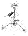
- the device 1 comprises a plurality of means for acquiring environmental data to be described shortly, each dedicated to the detection and measurement of specific local information and parameters.
- the aforesaid acquisition means can, according to the application whereto they are dedicated, be supported on a frame 2 of the device 1, which in the present embodiment comprises a structure 2 shaped substantially as a tripod and constructed with telescopic tubes.
- Said structure 3 is anchored to the ground by means of conventional fastening means 4, and it comprises a stabilisation ballast 5.
- the structure 3 also sustains a platform 6 apt to support some of the aforesaid means for acquiring environmental data necessary for the intended aim.
- the device 1 comprise image detection means 7 and thermal detection means 9, the latter apt to detect critical temperature variations in the area of interest, in the present application associated with the development of a flame, i.e. to identify temperature anomalies and possibly detect the flame core in the monitored portion of territory.
- Both said means 7 and 9 are suitable for various alternative embodiments.
- the image detection means 7 and the thermal detection means 9 comprise three common telecameras, housed on the platform 6 and each indicated with the reference 8.
- the telecameras 8 are positioned at a relative angular distance of about 120 degree from each other, in order to cover the surrounding space for 360 degrees. As shall be illustrated shortly, the telecameras 8 are apt to operate both in the visible and in the infrared range.
- the telecameras 8, if necessary, are provided with actuation means (not show herein) that allow both lateral and up/down motions and that are commanded by a local management and control unit 15 to be described farther on. Also the operational parameters and the functions of the telecameras 8, for instance the close/far zoom function, can be commanded by the aforesaid local management and control unit 15.
- the thermal detection means 9 are of the multi-band type and apt to obtain, for each telecamera 8, infrared images, and hence emission of infrared energy potentially associated with the presence of thermal anomaly phenomena, for instance the presence of a flame.
- the means 7 and 9 comprise a single common telecamera mounted on a rotatable platform 93 and otherwise similar to the telecameras of the first embodiment. Therefore, the means 7 and 9 of said first and second embodiments shall now be described in greater detail with reference to the aforesaid Figure 3A and 3B.
- the, or each, telecamera 8 provides both a visualisation means in the visible field and a thermal detection means for acquiring infrared images, i.e. it is a so-called thermo-camera.
- a thermal detection means for acquiring infrared images
- thermo-camera for this purpose, it is provided with an infrared microbolometric sensor.
- the telecameras 8 are associated two distinct acquisition boards, one, indicated as 900, for acquiring standard video images in the visible range and another, indicated as 901, for acquiring infrared images. These boards thus provide interface means between the telecamera (visible and IR) and the management and control unit 15.
- Warm bodies emit electromagnetic radiation on multiple wavelengths.
- the warmer a body is, the more infrared radiation it will emit as an effect of the thermal agitation of its molecules or atoms.
- the specific spectral distribution of the emitted radiation depends on the nature of the body and on its temperature. For example, dark colours and opaque surfaces generally have high emissivity and irradiate with greater effectiveness.
- thermo-camera by detecting the infrared energy emitted by the bodies, the thermo-camera generates a real time image and provides a thermal trace of the scene, highlighting relative temperature differences between adjacent areas.
- the aforesaid microbolometric sensor uses one or more appropriate lenses, for instance telescopic lenses, to develop a visual matrix in pixels, for instance a matrix (327 ⁇ 245), that is acquired by the thermo-camera and transmitted to the aforementioned local management and control unit 15.
- appropriate lenses for instance telescopic lenses
- a visual matrix in pixels for instance a matrix (327 ⁇ 245)
- thermo-camera is apt to detect and amplify the electromagnetic energy emitted in the form of heat.
- the sensitivity of the thermo-camera provided in the present embodiment is such as to allow to detect temperature differences of less than 0.1°C.
- thermal detection means 9 are implemented through means that are already known in the art, they shall not be further described herein. Nonetheless, for the sake of the completeness of the description and purely by way of indication, an example of their possible technical specifications, suitable for the present forest fire detection application, is provided hereafter.
- the thermal bands and the operating characteristics of the thermal detection means 9 can be identified as follows: Spectral bands: NUMBER 4 band 1: 8.2 +9.0 ⁇ m (heat mapping of the flames) band 2: 10.3 ⁇ 11.3 ⁇ m (environmental mapping) band 3: 11.5 ⁇ 12.5 ⁇ m (heat mapping of the flames) band 4: 8.2 ⁇ 12.5 ⁇ m (large space mapping) dynamic ranges 0 to 400 xK (wide area coverage) 0 to 1300 xK (detected flame mapping) NEDT @ 300 xK 0.005 xK (80-12.5 U) Spatial resolution 0.9 mr Surveillance area - elevation 17 degrees azimuth selectable (pan coverage) 0 to 360 degrees optics 50 mm f/0.73 calibration Real time, multi-level through the lenses weight about 25 kg dimensions (23x31x56) cm absorption 35W Power supply 28V DC or 230V 50 Hz data rate 41 Kbytes/s data display Real time - calibrated in the video data
- thermo-camera suitable to the present fire detection application.
- RGB colour palettes 4 sets functions focus, colour palette, store, play and freeze image, auto image, manual image, movable temperature cursor on both live and frozen images, emissivity settings image storage 52 images in 32 Mb Pc card compensations Temperature compensation for background, ambient temperature, distance and humidity dimensions (177 ⁇ 110 ⁇ 142) mm without lenses weight 2.1 kg
- the device 1 also comprises additional means 10 for measuring environmental data, in particular meteorological data, also housed on the platform 6.
- said means 10 comprise sensor means apt to measure wind speed and direction, humidity, pressure, temperature of the air, of the ground, dew temperature.
- location means 11 of the device On the platform 6 are also supported location means 11 of the device 1, in particular a GPS system ("Global Positioning System''), apt to allow the automatic determination of the geographic co-ordinates (latitude, longitude and altitude over sea level) of the device 1 itself.
- GPS system Global Positioning System''
- the device 1 further comprises means 12 for transmitting/receiving data to/from the aforementioned remote central control station 101, based for instance on GPS/GPRS or UMTS telephone transmission technology, on a fibre optics transmission technology, on a radio-frequency transmission technology in general or on dedicated data lines (Ethernet).
- Said means 12 allow, among other things, the transmission of data, also in the form of images, acquired by the different acquisition means introduced heretofore to the remote central control station 101.
- the means 12 are implemented by means of a data translation system (e.g. network board for data line or optical transducer for fibre optics, etc.) positioned in correspondence with the platform 6 or fastened on the tripod structure 3 inferiorly to the platform 6 itself.
- a data translation system e.g. network board for data line or optical transducer for fibre optics, etc.
- the device 1 also comprises self-powering means 13, in particular a photovoltaic panel and associated known means for converting and transmitting energy. Moreover, the device 1 also comprises energy accumulators or batteries 14, associated to the photovoltaic panel or independent therefrom.
- the device 1 can comprise a power supply from the electrical mains.
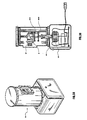
- the device 1 lastly comprises the aforementioned local unit 15 for managing and controlling its various components, which naturally is in bilateral communication with all the components introduced heretofore, and in particular with the transmission/reception means 12 for sending data to the remote central control station 101.
- the unit 15 is represented as physically subdivided in two connected sub-units, and in particular a first sub-unit 151, comprising the electronics for managing and controlling the telecameras 8, of the thermal detection means 9 in general and of the GPS system 11, and a second sub-unit 152, comprising means for managing and controlling the remaining components of the device 1.
- a first sub-unit 151 comprising the electronics for managing and controlling the telecameras 8, of the thermal detection means 9 in general and of the GPS system 11, and a second sub-unit 152, comprising means for managing and controlling the remaining components of the device 1.
- the unit 15 can be entirely housed inside a single case, or be divided into more than two sub-units, physically separated and mutually connected.
- connection between the unit 15 and the different components of the device 1 and the connection between the sub-units 151 and 152 are achieved by means of conventional data transmission lines 16, shielded for instance by means of corrugated pipes.
- the unit 15 comprises means 17 for locally processing the data acquired by the different environmental acquisition means of the device 1.
- the unit 15 comprises means for processing the data coming from the thermal detection means 9, which processing means are apt to compare the obtained data with pre-determined thresholds to detect temperature variations to be considered critical for the type of environment monitored.
- the aforesaid means for processing the data coming from the thermal detection means 9 operate as follows. Said processing means receive from the means 9 the aforesaid visual matrix in pixels and analyse it by means of a known algorithm which provides for an infrared scan over a plurality of appropriate thermal bands apt to digitise a spectrum with at least 80,000 pixels.
- the processing means perform the correction of the scanned pixels and define calibration parameters automatically, by means of a specific known analysis algorithm.
- the first scan is interpreted and analysed in a base band (wide infrared band 2 ⁇ 100 ⁇ m).
- a base band wide infrared band 2 ⁇ 100 ⁇ m.
- the analysis of the event is re-processed on other thermal bands suitable for the purpose, in order to identify in particular the pixel that generated the anomaly and to analyse the anomaly in greater detail. If the anomaly is due to an event considered critical, i.e.
- the processing means record the event digitising the images and sending an alarm signal to the remote central control station 101.
- Said alarm signal is thus typically associated to the detection of energy emissions of a predetermined entity, i.e. exceeding a predetermined threshold. Otherwise, i.e. if the anomaly is classified as not due to a critical event, but to other events such as the passage of a motor vehicle or an anomalous and temporary thermal flow, the processing means automatically raise the detection threshold for that given pixel and reprocess the scan so that no alarm signal is generated.
- This technology for instance in the field of application for monitoring and controlling forest fires, allows to detect a flame with a height of about 20 cm at a distance of about 10 km, without generating false alarms.
- the processing means can also command the related telecamera 8 for the acquisition of images in the visible range of the area where the supposed critical event is developing.
- the local processing means 17 are also apt to compute, co-operating with the aforesaid GPS 11 system, the geographic co-ordinates of the critical fire event detected, i.e. of the temperature variation assessed as critical.
- the local unit 15 transmits to the central control station 101, through the means 12, the images acquired by the telecameras 8 in visual and infrared mode in digitised form.
- the unit 15 also comprises means for locally storing the acquired data, possibly after their processing, which means 18 may possibly be associated with an analogic/digital converter of the data.
- the processing of the data acquired locally by the device 1, and in particularly the processing of the data coming from the thermal detection means 9 described above, can be performed directly by specific processing units incorporated in the acquisition means themselves or remotely, i.e. in the central control station 101.
- processing and storage means can be implemented by means of conventional hardware and/or software components, they shall not be described any further herein.
- the central station 101 is apt to receive and transmit data from/to the local devices 1, to manage the acquisition means thereof and to alert competent authorities in case of detection of a temperature anomaly and/or possible fires.
- the central station 101 comprises processing means, storage means and means for interfacing with its operators which are described hereafter.
- the central station 101 comprises a plurality of storage units, hereinafter referred to as database units 102, each apt to store logistical, technical and/or topographic information about the environment to be monitored, necessary for an integrated processing of the data coming from the local devices 1.
- database units 102 each apt to store logistical, technical and/or topographic information about the environment to be monitored, necessary for an integrated processing of the data coming from the local devices 1.
- the central station 101 comprises:
- the aforesaid information about the intended use for the area (or, in alternative applications, about facilities and/or machinery) and to its morphological and naturalistic makeup can also be updated in real time by means of the data acquired by the local monitoring devices 1.
- the central station 101 also comprises means 103 for the integrated processing of the data coming from the different monitoring devices 1 distributed over the areas of interest (or, in alternative applications, inside the facilities). Said integrated processing means 103 are apt to process the data coming from the local devices 1 and the information contained in the aforesaid database units 102, in such a way as to provide the operators of the central station 101 and/or additional connected operative centres with output information allowing to plan the operations with exactness.
- the integrated processing means 103 are apt to extract from the aforesaid database units 102, upon specific interrogation and/or automatically, all the information referring to the specific area involved with the event as identified in the alarm signal send by one or more of the local monitoring devices 1.
- said integrated processing means 103 are apt to compute a model of the evolution of the fire event (or, in alternative applications, of the thermal front, i.e. of the propagation of the heat wave) according to the data provided by the thermal detection means 9, to the environmental parameters provided by the means 10 and to the morphological and naturalistic characteristics of the involved area stored in the appropriate database unit 102, identifying the areas potentially exposed to the risk of damage and/or fire surrounding the zone where the thermal anomalies and/or flames were detected.
- the integrated processing means 103 are also apt to prepare a plan of intervention, indicating the methods and paths available among those stored in the appropriate database unit 102 and proposing an optimal plan for reaching the area involved in the processed event considering the aforesaid model of evolution of the fire event, the number and the type of rescue means and human resources currently available in proximity to the interested area or potentially involved by the flames, the logistical-topographic characteristics of the area and the need to minimise the time needed to reach said area.
- the processing means 103 are also apt to provide multiple alternative processes and paths, associating to each of them an estimate of the time required to intervene and extinguish the fire, i.e. in general of the starting and/or ending times of the intervention.
- processing means 103 can also adaptively modify the evolution model of the aforesaid fire event as a function of the intervention plan selected by the operators by means of appropriate interface means of the central station 101.
- the model of evolution of the fire is based on a function with (n + 4) variables, function which is defined according to the specific intended application of the system.
- the n variables are determined by the specific territory to be monitored, for instance wooded area or industrial facility, the remaining four are time and the three spatial co-ordinates.
- the foremost hypothesis for determining the model of evolution is based on the analysis of the evolution of the event under standard and/or ideal conditions, in an isotropic and homogeneous medium, defined as model zero. Under such conditions, the development system is known, analysable and reproducible. In the basic model analysed by modifying the parameters of the base model itself and introducing the values detected on site, the values of the environmental variables that are significant for the evolution are modified, and the new descriptive algorithm thereof is determined.
- the significant variables for the event are those that were determined and fixed during the analysis of the basic model (ideal conditions).
- the basic variable are:
- the model followed to develop the intervention plant to be implemented is based on the ideal intervention that should be carried out on the basic model (ideal conditions), when the propagation front of the event, in particular of the heat and/or of the fire, has reached the size of the one set at time t.
- the optimal intervention plan is prepared, which can also be modified adaptively according to the real time acquisitions of the acquisition means of the local devices 1 and of the measurements taken on site by the intervention teams and communicated to the central station 101 through conventional data transmission/reception means.
- the processing means 103 can also, according to the processed evolution model, classify the event with a danger index, estimating its possible environmental and economic consequences.
- the danger index can help assess, in case of simultaneous alarm events, the correct allocation of the available resources.
- the aforementioned processing of the data provided by the thermal detection means 9 can also be carried out by the integrated processing means 103 rather than by the local management and control unit 15.
- the central station 101 further comprises interface means 104 for communicating the data acquired by the local devices 1 and the data processed in integrated fashion by the means 103 to the operators of the central station itself and to allow the operators themselves to interrogate the central station 101 and manage the local devices 1.
- Said interface means 104 comprise for example a plurality of units for displaying the images in the visible and/or infrared band sent by the different local control devices 1 and a console for managing the measured data.
- the central 101 further comprises communication means 105 dedicated to alert and send instructions to the cognisant bodies for carrying out the intervention plan on a local, provincial, regional and national scale.
- the central station 101 can be connected to maintenance teams, the fire brigade, the national forestry corps, civil protection, local agencies (towns, provinces), volunteer organisations, mountain communities, organizations, WWF, local health care unit, police, transport agencies, road agency, energy agency, information media, airports and so on.
- central station 101 can be implemented by means of known hardware and/or software means, it will not be described any further herein.
- the system of the invention allows to detect, locate and display a significant temperature variation deemed critical for the development of a fire, for the normal operation of a facility and so on, and to process and transmit information about the critical event detected and about the intervention for its containment / extinguishing in real time and twenty-four hours a day.
- the system of the invention thus allows effective and safe interventions.
- the detection means apt to detect the presence of temperature variations can have multiple alternative implementations (detection of fires, mechanical malfunctions, modifications of the molecular state, etc.).
- the thermal detection means in this case also indicated as 9, are implemented by means of an infrared telecamera mounted on a rotatable platform similar to that of the embodiment described with reference to Figures 3A and 3B.
- the aforesaid thermo-camera is complemented by three telecameras 8 operating only in the visible range and positioned at an angular distance of about 120 degree from each other.
- the remaining components of the device shown in Figure 4 are wholly similar to those of the first embodiment described above, with the exception of the photovoltaic 13, which has a greater capacity, and of the management and control unit 15, which is constructed in a single body.
- the local devices can employ as support structures, instead of the dedicated frame based on a tripod structure described above, structures already existing on the territory, for instance uprights, trestles or supporting posts for telephone or electrical power lines.
- the system of the invention comprises a single local monitoring device.
Landscapes
- Engineering & Computer Science (AREA)
- Physics & Mathematics (AREA)
- Life Sciences & Earth Sciences (AREA)
- Business, Economics & Management (AREA)
- Emergency Management (AREA)
- General Physics & Mathematics (AREA)
- Thermal Sciences (AREA)
- Sustainable Development (AREA)
- Sustainable Energy (AREA)
- Multimedia (AREA)
- Chemical & Material Sciences (AREA)
- Combustion & Propulsion (AREA)
- Mechanical Engineering (AREA)
- General Engineering & Computer Science (AREA)
- Biodiversity & Conservation Biology (AREA)
- Alarm Systems (AREA)
- Selective Calling Equipment (AREA)
- Photometry And Measurement Of Optical Pulse Characteristics (AREA)
- Radiation Pyrometers (AREA)
- Fire-Detection Mechanisms (AREA)
- Fire Alarms (AREA)
- Burglar Alarm Systems (AREA)
- Control Of Temperature (AREA)
Claims (31)
- Umgebungsüberwachungssystem (100), mit:- wenigstens einer unbemannten, auf dem Boden anzuordnenden lokalen Vorrichtung (1), die dafür ausgebildet ist, in der zu überwachenden Umgebung installiert zu werden, und Erfassungseinrichtungen (7, 8, 9, 10) zum Erfassen von Umgebungsdaten hat, welche dafür ausgebildet sind, kritische thermische Veränderungen in dem interessierenden Bereich zu erkennen;- einer zentralen Steuerungsstation (101), die eine Speichereinrichtung (102) aufweist zum Speichern von logistischen technischen Daten sowie von Daten über verfügbare Interventionseinrichtungen, die zu der überwachten Umgebung gehören;- einer Einrichtung (12) zum Senden/Empfangen von Daten zur bilateralen Kommunikation zwischen der zentralen Steuerungsstation (101) und der wenigstens einen lokalen Vorrichtung (1); und- einer Einrichtung (103) zum integrierten Verarbeiten der Umgebungsdaten, die durch die wenigstens eine lokale Vorrichtung (1) erfasst worden sind, und der Daten, die in der Speichereinrichtung (102) enthalten sind, und die dafür ausgebildet ist, als ihr Ausgangssignal ein Modell der Evolution der Wärmefront zu liefern, welche die Folge einer kritischen thermischen Veränderung ist, und einen Interventionsplan zum Begrenzen der damit verbundenen Schäden,wobei die Erfassungseinrichtung der wenigstens einen lokalen Vorrichtung (1) umfasst: eine Branderkennungseinrichtung (9) zum Erkennen von Energieemissionen im IR-Bereich; eine Erfassungseinrichtung (10) für meteorologische Daten; und eine Bilderfassungseinrichtung (7), die wenigstens eine Telekamera (8) umfasst, welche im sichtbaren Bereich arbeitet, wobei die Branderkennungseinrichtung (9) dafür ausgebildet ist, die Aktivierung der Telekamera (8) als Antwort auf das Erkennen von Energieemissionen hin, welche einen vorbestimmten Schwellenwert überschreiten, zu bewirken, und
wobei die wenigstens eine lokale Vorrichtung (1) eine eigene Stromversorgungseinrichtung (13, 14) und eine Tragkonstruktion (3) aufweist, welche die Erfassungseinrichtung (9) trägt und dafür ausgebildet ist, am Boden an einem gewünschten Ort verankert zu werden. - System (100) nach Anspruch 1, mit einer Vielzahl von lokalen Vorrichtungen (1), die dafür ausgebildet sind, in der zu überwachenden Umgebung installiert zu werden.
- System (100) nach einem der vorhergehenden Ansprüche, mit einer Einrichtung (17) zum Verarbeiten der Energieemissionen, die durch die Erkennungseinrichtung (9) erkannt werden, und die dafür ausgebildet ist, die Emissionen in einer Vielzahl von Emissionsbändern zu analysieren.
- System (100) nach einem der vorhergehenden Ansprüche, wobei die Erkennungseinrichtung (9) wenigstens eine Wärmekamera umfasst, die im IR-Bereich arbeitet.
- System (100) nach dem vorhergehenden Anspruch, wobei die Wärmekamera mit einem mikrobolometrischen IR-Sensor versehen ist.
- System (100) nach einem der vorhergehenden Ansprüche, wobei die Einrichtung (12) zum Senden/Empfangen von Daten in der Lage ist, Bilder aus der (den) lokalen Vorrichtung(en) (1) zu der zentralen Steuerungsstation (101) in einer sichtbaren und/oder IR-Betriebsart zu übertragen.
- System (100) nach einem der vorhergehenden Ansprüche, wobei die Erkennungseinrichtung (10) für meteorologische Daten eine Erfassungseinrichtung aufweist, die aus einer Gruppe ausgewählt ist, welche Einrichtungen umfasst zum Messen der Windgeschwindigkeit und -richtung, der Feuchtigkeit, des Druckes, der Luft- und Bodentemperatur und der Taupunktstemperatur.
- System (100) nach dem vorhergehenden Anspruch, wobei die Erkennungseinrichtung (10) für meteorologische Daten mit Sensoren ausrüstbar ist zum Erkennen von Parametern, die als notwendig angesehen werden für die korrekte Analyse der Erscheinung von thermischen Veränderungen und von deren Evolutionsmodell.
- System (100) nach einem der vorhergehenden Ansprüche, wobei die Erfassungseinrichtungen eine Lokalisierungseinrichtung (11) umfassen, die dafür ausgebildet ist, die automatische Bestimmung der geografischen Koordinaten der zugeordneten lokalen Vorrichtung (1) zu erlauben.
- System (100) nach einem der vorhergehenden Ansprüche, mit Einrichtungen (17, 11), die dafür ausgebildet sind, die geographischen Koordinaten einer thermischen Veränderung zu bestimmen, welche durch die Einrichtung (9) zum Erfassen von Umgebungsdaten erkannt wird.
- System (100) nach einem der vorhergehenden Ansprüche, wobei wenigstens eine lokale Vorrichtung (1) eine lokale Verarbeitungseinrichtung (17) für die erfassten Daten aufweist.
- System (100) nach einem der vorhergehenden Ansprüche, wobei wenigstens eine lokale Vorrichtung (1) eine lokale Speichereinrichtung (18) für die erfassten Daten aufweist.
- System (100) nach einem der vorhergehenden Ansprüche, wobei die Tragkonstruktion (3) zum Tragen der Erfassungseinrichtung (9) im Wesentlichen die Form eines Dreibeins hat.
- System (100) nach dem vorhergehenden Anspruch, wobei die Tragkonstruktion (3) eine Plattform (6) umfasst, die entsprechend einem oberen Teil der Konstruktion selbst positioniert ist.
- System (100) nach einem der vorhergehenden Ansprüche, wobei wenigstens eine lokale Vorrichtung (1) eine drehbare Plattform (93) zum Tragen der Erfassungseinrichtungen (7, 8, 9, 10) aufweist.
- System (100) nach einem der vorhergehenden Ansprüche, wobei der Interventionsplan die Anzeige von wenigstens einem optimalen Zugangspfad zum Erreichen des Gebiets enthält, das von einer kritischen thermischen Veränderung betroffen ist.
- System (100) nach einem der vorhergehenden Ansprüche, wobei der Interventionsplan einen Schätzwert der Start- und/oder Endzeiten der Intervention enthält.
- System (100) nach einem der vorhergehenden Ansprüche, wobei die zentrale Steuerungsstation (101) eine Schnittstelleneinrichtung (104) umfasst, um Bedienungspersonen zu erlauben, einen Interventionsplan auszuwählen, und wobei die integrierte Verarbeitungseinrichtung (103) in der Lage ist, das Modell der Evolution der Wärmefront gemäß dem durch die Bedienungspersonen der zentralen Steuerungsstation (101) ausgewählten Interventionsplan adaptiv zu modifizieren.
- System (100) nach einem der vorhergehenden Ansprüche, wobei die integrierte Verarbeitungseinrichtung (103) eine Einrichtung aufweist, die dafür ausgebildet ist, die erfasste thermische Veränderung gemäß einem Gefahrenindex zu klassifizieren.
- System (100) nach einem der vorhergehenden Ansprüche, wobei die zentrale Steuerungsstation (101) eine Schnittstelleneinrichtung (104) aufweist, die dafür ausgebildet ist, den Bedienungspersonen die durch die lokale(n) Vorrichtungen(en) (1) erfassten Daten und die von der integrierten Verarbeitungseinrichtung (103) abgegebenen Daten zu übermitteln, und dafür ausgebildet ist, die Befragung der Speichereinrichtung (102) zu erlauben.
- System (100) nach einem der vorhergehenden Ansprüche, wobei die zentrale Steuerungsstation (101) eine Schnittstelleneinrichtung (104) aufweist, die dafür ausgebildet ist, das Management der Erfassungseinrichtungen (7, 8, 9, 10) der lokalen Vorrichtung(en) (1) durch die Bedienungspersonen der zentralen Station zu erlauben.
- System (100) nach einem der vorhergehenden Ansprüche, mit einer Einrichtung (105) zum Kommunizieren mit Agenturen zum Ausführen des Interventionsplanes.
- Verfahren zur Umgebungsüberwachung, beinhaltend die Schritte:a) Installieren von wenigstens einer unbemannten, auf dem Boden anzuordnenden lokalen Vorrichtung (1), die Erfassungseinrichtungen (7, 8, 9, 10) zum Erfassen von Umgebungsdaten hat und dafür ausgebildet ist, kritische thermische Veränderungen in dem interessierenden Gebiet zu erkennen, auf dem zu überwachenden Territorium;b) Speichern von logistischen technischen Daten und von Daten über verfügbare Interventionseinrichtungen, welche sich auf die überwachte Umgebung beziehen, in einer zentralen Steuerungsstation (101) und;c) Verarbeiten der erfassten Umgebungsdaten und der gespeicherten logistischen technischen Daten in einer integrierten Betriebsart derart, dass ein Modell der Evolution der Wärmefront geschaffen wird, welche die Konsequenz einer kritischen thermischen Veränderung ist, und eines Interventionsplans zum Begrenzen der damit verbundenen Schäden,wobei die Erfassungseinrichtung der wenigstens einen lokalen Vorrichtung (1) aufweist: eine Branderfassungseinrichtung (9) zum Erkennen von Energieemissionen im IR-Bereich; eine Erkennungseinrichtung (10) für meteorologische Daten; und eine Bilderfassungseinrichtung (7), die wenigstens eine Telekamera (8) aufweist, welche im sichtbaren Bereich arbeitet, wobei die Branderkennungseinrichtung (9) in der Lage ist, die Aktivierung der Telekamera (8) auf das Erfassen von Energieemissionen hin, welche einen vorbestimmten Schwellenwert überschreiten, zu bewirken, und wobei die wenigstens eine lokale Vorrichtung (1) eine eigene Stromversorgungseinrichtung (13, 14) und eine Tragkonstruktion (3), welche die Erfassungseinrichtung (9) trägt und dafür ausgebildet ist, auf dem Boden an einem gewünschten Ort verankert zu werden, aufweist.
- Verfahren nach Anspruch 23, wobei der Schritt a) vorsieht, dass mehrere Erfassungseinrichtungen (7, 8, 9, 10) installiert werden, die in der zu überwachenden Umgebung verteilt werden.
- Verfahren nach Anspruch 23 oder 24, beinhaltend einen Schritt zum Verarbeiten der Energieemissionen, die durch die Erkennungseinrichtung (9) erkannt werden, wobei die verfassten Daten in mehreren Emissionsbändern analysiert werden.
- Verfahren nach einem der Ansprüche 23 bis 25, beinhaltend den Schritt, Daten aus der Erfassungseinrichtung (9) zu der zentralen Steuerungsstation (101) zu übertragen, die für die Übertragung von Bildern in einer Sichtbar- und/oder IR-Betriebsart sorgt.
- Verfahren nach einem der Ansprüche 23 bis 26, beinhaltend einen Schritt zum Bestimmen der geographischen Koordinaten einer thermischen Veränderung, die durch die Einrichtung (9) zum Erfassen von Umgebungsdaten erkannt wird.
- Verfahren nach einem der Ansprüche 23 bis 27, wobei der Interventionsplan die Angabe von wenigstens einem optimalen Zugangspfad zum Erreichen des von der kritischen thermischen Veränderung betroffenen Gebietes enthält.
- Verfahren nach einem der Ansprüche 23 bis 28, wobei der Interventionsplan einen Schätzwert der Start- und/oder Endzeiten der Intervention enthält.
- Verfahren nach einem der Ansprüche 23 bis 29, wobei der Schritt c) für eine adaptive Modifikation des Evolutionsmodells der Wärmefront gemäß dem Interventionsplan sorgt, der durch die Bedienungspersonen der zentralen Steuerungsstation (101) ausgewählt worden ist.
- Verfahren nach einem der Ansprüche 23 bis 30, wobei der Schritt c) das Klassifizieren der erfassten thermischen Veränderung gemäß einem Gefahrenindex beinhaltet.
Applications Claiming Priority (1)
| Application Number | Priority Date | Filing Date | Title |
|---|---|---|---|
| PCT/IT2002/000464 WO2004008407A1 (en) | 2002-07-16 | 2002-07-16 | System and method for territory thermal monitoring |
Publications (2)
| Publication Number | Publication Date |
|---|---|
| EP1523738A1 EP1523738A1 (de) | 2005-04-20 |
| EP1523738B1 true EP1523738B1 (de) | 2007-02-28 |
Family
ID=30012282
Family Applications (1)
| Application Number | Title | Priority Date | Filing Date |
|---|---|---|---|
| EP02765325A Expired - Lifetime EP1523738B1 (de) | 2002-07-16 | 2002-07-16 | System und verfahren zur thermischen überwachung eines gebietes |
Country Status (12)
| Country | Link |
|---|---|
| US (1) | US20070000317A1 (de) |
| EP (1) | EP1523738B1 (de) |
| JP (1) | JP2005539287A (de) |
| CN (1) | CN1639751A (de) |
| AT (1) | ATE355576T1 (de) |
| AU (1) | AU2002329039A1 (de) |
| BR (1) | BR0215800A (de) |
| CA (1) | CA2492360A1 (de) |
| DE (1) | DE60218544D1 (de) |
| ES (1) | ES2283591T3 (de) |
| PT (1) | PT1523738E (de) |
| WO (1) | WO2004008407A1 (de) |
Families Citing this family (41)
| Publication number | Priority date | Publication date | Assignee | Title |
|---|---|---|---|---|
| US7676590B2 (en) | 2004-05-03 | 2010-03-09 | Microsoft Corporation | Background transcoding |
| ITRM20040245A1 (it) * | 2004-05-14 | 2004-08-14 | Gen Contractor S R L | Metodo per il rilevamento volumetrico ottimizzato di eventi su un'area geografica, apparato utilizzante tale metodo e relativo sistema di rilevamento. |
| ITMI20041607A1 (it) * | 2004-08-05 | 2004-11-05 | Milano Politecnico | Sistema elettronico per la difesa contro incendi del territorio boschivo e piu' in generale per il monitoraggio del territorio |
| DE102004056958B3 (de) | 2004-11-22 | 2006-08-10 | IQ wireless GmbH, Entwicklungsgesellschaft für Systeme und Technologien der Telekommunikation | Verfahren für die Überwachung von Territorien zur Erkennung von Wald- und Flächenbränden |
| US9436804B2 (en) | 2005-04-22 | 2016-09-06 | Microsoft Technology Licensing, Llc | Establishing a unique session key using a hardware functionality scan |
| JP2007003308A (ja) * | 2005-06-22 | 2007-01-11 | Pasuko:Kk | 地表面温度推定方法及びそのためのプログラム |
| PT103304B (pt) | 2005-07-07 | 2007-06-29 | Univ Nova De Lisboa | Sistema para a detecção automática de incêndios florestais por espectroscopia óptica |
| US7924913B2 (en) | 2005-09-15 | 2011-04-12 | Microsoft Corporation | Non-realtime data transcoding of multimedia content |
| CA2700035A1 (en) * | 2007-09-19 | 2009-03-26 | United Technologies Corporation | System and method for threat propagation estimation |
| US20100102992A1 (en) * | 2008-10-28 | 2010-04-29 | Honeywell International Inc. | Systems and methods for remote monitoring of weather |
| IT1394450B1 (it) * | 2009-06-17 | 2012-06-15 | Teletron Euroricerche S R L | Metodo di prevenzione e/o di rilevazione di un incendio, e relativi sistema di controllo e prodotto informatico |
| GB0920636D0 (en) * | 2009-11-25 | 2010-01-13 | Cyberhawk Innovations Ltd | Unmanned aerial vehicle |
| CN102280005B (zh) * | 2011-06-09 | 2014-10-29 | 广州飒特红外股份有限公司 | 基于红外热成像技术的森林防火预警系统及方法 |
| CN105122633B (zh) | 2013-04-09 | 2019-04-05 | 热成像雷达有限责任公司 | 步进电机控制系统及方法 |
| CN105074789B (zh) * | 2013-04-09 | 2019-03-12 | 热成像雷达有限责任公司 | 火灾检测系统 |
| EP3030935B1 (de) | 2013-08-09 | 2020-11-18 | Thermal Imaging Radar LLC | Verfahren zur analyse von wärmebilddaten mittels einer vielzahl virtueller vorrichtungen und verfahren zur korrelation von tiefenwerten zu bildpixeln |
| US10552911B1 (en) * | 2014-01-10 | 2020-02-04 | United Services Automobile Association (Usaa) | Determining status of building modifications using informatics sensor data |
| US9565081B2 (en) | 2014-05-19 | 2017-02-07 | Ebay Inc. | Phone thermal context |
| DE112015002761B4 (de) * | 2014-06-12 | 2024-02-01 | Ihi Corporation | Lageraufbau und turbolader |
| CN104200607B (zh) * | 2014-09-19 | 2016-07-06 | 西南大学 | 一种森林火灾监控系统 |
| CN105572680A (zh) * | 2014-10-08 | 2016-05-11 | 上海新跃仪表厂 | 高层建筑火情定位系统与方法 |
| US10366509B2 (en) | 2015-03-31 | 2019-07-30 | Thermal Imaging Radar, LLC | Setting different background model sensitivities by user defined regions and background filters |
| CN106558181B (zh) * | 2015-09-28 | 2019-07-30 | 东莞前沿技术研究院 | 火灾监测方法和装置 |
| ITUB20155886A1 (it) * | 2015-11-25 | 2017-05-25 | A M General Contractor S P A | Rilevatore d?incendio a radiazione infrarossa con funzione composta per ambiente confinato. |
| DE102016000661B3 (de) * | 2016-01-22 | 2017-05-24 | IQ-Wireless GmbH Entwicklungsges. für Systeme und Technologien der Telekommunikation | Vorrichtung für die Installation einer optischen Sensorlösung zur automatisierten Waldbrandfrüherkennung und Verfahren zu dessen Einrichtung und Kalibrierung |
| CN105516693A (zh) * | 2016-02-19 | 2016-04-20 | 国网山东省电力公司滨州供电公司 | 一种多功能用电检查装置 |
| CN108242052A (zh) * | 2016-12-23 | 2018-07-03 | 航天星图科技(北京)有限公司 | 一种应用于农田的火点确定方法 |
| US10574886B2 (en) | 2017-11-02 | 2020-02-25 | Thermal Imaging Radar, LLC | Generating panoramic video for video management systems |
| US11022699B1 (en) | 2017-11-22 | 2021-06-01 | Cory A. Webb | External solar power source for global positioning system (GPS) base stations |
| US20190236922A1 (en) * | 2018-01-30 | 2019-08-01 | The Boeing Company | Optical Cabin and Cargo Smoke Detection Using Multiple Spectrum Light |
| US10860614B2 (en) * | 2018-03-19 | 2020-12-08 | Landis+Gyr Innovations, Inc. | Partitioning data in a clustered database environment |
| CN108428330A (zh) * | 2018-03-22 | 2018-08-21 | 安徽八六物联科技有限公司 | 一种声光联合的预警装置 |
| CN109506694B (zh) * | 2018-11-29 | 2019-11-19 | 莱芜职业技术学院 | 一种环境监测装置平台 |
| CN110610586A (zh) * | 2019-09-09 | 2019-12-24 | 生态环境部南京环境科学研究所 | 一种预防森林火灾的安全监控装置 |
| KR102143297B1 (ko) * | 2019-09-18 | 2020-08-10 | 창원대학교 산학협력단 | 미기상 정보수집용 종합환경계측기 |
| US11601605B2 (en) | 2019-11-22 | 2023-03-07 | Thermal Imaging Radar, LLC | Thermal imaging camera device |
| CN112834062B (zh) * | 2019-11-22 | 2023-03-21 | 北京广利核系统工程有限公司 | 一种基于感温元件的信号采集方法及系统 |
| CN111862515B (zh) * | 2020-06-28 | 2022-04-12 | 安徽旭帆信息科技有限公司 | 一种基于红外成像和视频分析的火灾识别装置 |
| CN112419644A (zh) * | 2020-08-07 | 2021-02-26 | 西安科技大学 | 一种森林火灾应急救援风速风向监测预警系统及方法 |
| CN115223325A (zh) * | 2022-07-07 | 2022-10-21 | 深圳市环宇星科技有限公司 | 一种能识别火灾的ai摄像头及其控制系统 |
| CN116540326B (zh) * | 2023-04-06 | 2024-05-24 | 自然资源部第二海洋研究所 | 一种海洋气象观测设备 |
Family Cites Families (13)
| Publication number | Priority date | Publication date | Assignee | Title |
|---|---|---|---|---|
| DE3710265A1 (de) * | 1987-03-28 | 1988-10-13 | Licentia Gmbh | Anlage zur frueherkennung von grossflaechigen braenden |
| US5734335A (en) * | 1989-12-20 | 1998-03-31 | Finmeccanica S.P.A. | Forest surveillance and monitoring system for the early detection and reporting of forest fires |
| ES2070710B1 (es) * | 1993-02-10 | 1997-05-01 | Nacional Bazan De Construccion | Sistema de vigilancia y deteccion de focos de calor en areas abiertas . |
| US5628050A (en) * | 1994-12-09 | 1997-05-06 | Scientific And Commercial Systems Corporation | Disaster warning communications system |
| US5832187A (en) * | 1995-11-03 | 1998-11-03 | Lemelson Medical, Education & Research Foundation, L.P. | Fire detection systems and methods |
| IL117521A0 (en) * | 1996-03-17 | 1996-10-31 | Israel Aircraft Ind Ltd Malat | A fire imaging system and method |
| US6169476B1 (en) * | 1997-02-18 | 2001-01-02 | John Patrick Flanagan | Early warning system for natural and manmade disasters |
| US6084510A (en) * | 1997-04-18 | 2000-07-04 | Lemelson; Jerome H. | Danger warning and emergency response system and method |
| US6212286B1 (en) * | 1998-09-18 | 2001-04-03 | John Edward Rott | Method for non-invasive and safe testing of telecommunication and broadcast towers or other airwave or cable transmitting and receiving devices |
| US6023223A (en) * | 1999-03-18 | 2000-02-08 | Baxter, Jr.; John Francis | Early warning detection and notification network for environmental conditions |
| US6553336B1 (en) * | 1999-06-25 | 2003-04-22 | Telemonitor, Inc. | Smart remote monitoring system and method |
| US6735630B1 (en) * | 1999-10-06 | 2004-05-11 | Sensoria Corporation | Method for collecting data using compact internetworked wireless integrated network sensors (WINS) |
| US6816878B1 (en) * | 2000-02-11 | 2004-11-09 | Steven L. Zimmers | Alert notification system |
-
2002
- 2002-07-16 US US10/521,222 patent/US20070000317A1/en not_active Abandoned
- 2002-07-16 AT AT02765325T patent/ATE355576T1/de not_active IP Right Cessation
- 2002-07-16 PT PT02765325T patent/PT1523738E/pt unknown
- 2002-07-16 CA CA002492360A patent/CA2492360A1/en not_active Abandoned
- 2002-07-16 JP JP2004521083A patent/JP2005539287A/ja active Pending
- 2002-07-16 DE DE60218544T patent/DE60218544D1/de not_active Expired - Lifetime
- 2002-07-16 EP EP02765325A patent/EP1523738B1/de not_active Expired - Lifetime
- 2002-07-16 ES ES02765325T patent/ES2283591T3/es not_active Expired - Lifetime
- 2002-07-16 CN CNA028293223A patent/CN1639751A/zh active Pending
- 2002-07-16 WO PCT/IT2002/000464 patent/WO2004008407A1/en not_active Ceased
- 2002-07-16 AU AU2002329039A patent/AU2002329039A1/en not_active Abandoned
- 2002-07-16 BR BR0215800-0A patent/BR0215800A/pt not_active IP Right Cessation
Also Published As
| Publication number | Publication date |
|---|---|
| CA2492360A1 (en) | 2004-01-22 |
| US20070000317A1 (en) | 2007-01-04 |
| WO2004008407A1 (en) | 2004-01-22 |
| ATE355576T1 (de) | 2006-03-15 |
| DE60218544D1 (de) | 2007-04-12 |
| CN1639751A (zh) | 2005-07-13 |
| EP1523738A1 (de) | 2005-04-20 |
| PT1523738E (pt) | 2007-06-06 |
| AU2002329039A1 (en) | 2004-02-02 |
| ES2283591T3 (es) | 2007-11-01 |
| JP2005539287A (ja) | 2005-12-22 |
| BR0215800A (pt) | 2005-03-01 |
Similar Documents
| Publication | Publication Date | Title |
|---|---|---|
| EP1523738B1 (de) | System und verfahren zur thermischen überwachung eines gebietes | |
| US5734335A (en) | Forest surveillance and monitoring system for the early detection and reporting of forest fires | |
| US9666050B2 (en) | Forest fire early-warning system and method based on infrared thermal imaging technology | |
| CA2301895C (en) | Apparatus and method for monitoring and reporting weather conditions | |
| RU2486594C2 (ru) | Способ мониторинга лесных пожаров и комплексная система раннего обнаружения лесных пожаров, построенная на принципе разносенсорного панорамного обзора местности с функцией высокоточного определения очага возгорания | |
| CA2047190C (en) | Fire fighting system mainly conceived to safeguard forests | |
| KR102507828B1 (ko) | 광범위한 부지에 대한 영공을 모니터링하기 위한 시스템 및 방법 | |
| EP0611242B1 (de) | System zur Überwachung und Detektierung von Wärmequellen in offenen Gebieten | |
| US12352920B2 (en) | System and method for detecting high-risk lightning strikes for use in predicting and identifying wildfire ignition locations | |
| KR101063922B1 (ko) | 목표물 위치 획득 및 감시시스템 | |
| CN101719300A (zh) | 智能视频火灾预警系统及其报警参数的确定方法 | |
| US20050103506A1 (en) | Fire protection method | |
| US20250104546A1 (en) | Systems for detecting and monitoring a small area wildfire and methods related thereto | |
| CN117690244A (zh) | 一种山火监测预警方法及装置 | |
| CN109903505A (zh) | 一种森林火情监测系统、方法及介质 | |
| RU2427006C2 (ru) | Оптико-электронный модуль большой дальности "фокус-д" | |
| De Vries et al. | Results with a multispectral autonomous wildfire detection system | |
| CN206945976U (zh) | 一种基于卫星遥感图像的自然灾害风险监测系统 | |
| LU101901B1 (en) | Fire alarm based on remote transmission of a thermal image | |
| Deeb et al. | Building envelope assessment using thermal infrared and lidar scanning: Palmer Station, Antarctica | |
| CN103354007B (zh) | 森林火灾监测方法及其装置 | |
| Blazquez | Detection of problems in high-power voltage transmission and distribution lines with an infrared scanner/video system | |
| RU2834502C1 (ru) | Комплекс охраны местности с применением беспилотного воздушного средства | |
| US20250029480A1 (en) | System and method for detecting high-risk-lightning strikes for use in predicting and identifying wildfire ignition locations and powerline damage points | |
| Indermuehle et al. | Using near real-time satellite data for severe weather protection of remote telescope facilities |
Legal Events
| Date | Code | Title | Description |
|---|---|---|---|
| PUAI | Public reference made under article 153(3) epc to a published international application that has entered the european phase |
Free format text: ORIGINAL CODE: 0009012 |
|
| 17P | Request for examination filed |
Effective date: 20050216 |
|
| AK | Designated contracting states |
Kind code of ref document: A1 Designated state(s): AT BE BG CH CY CZ DE DK EE ES FI FR GB GR IE IT LI LU MC NL PT SE SK TR |
|
| AX | Request for extension of the european patent |
Extension state: AL LT LV MK RO SI |
|
| GRAP | Despatch of communication of intention to grant a patent |
Free format text: ORIGINAL CODE: EPIDOSNIGR1 |
|
| GRAS | Grant fee paid |
Free format text: ORIGINAL CODE: EPIDOSNIGR3 |
|
| GRAA | (expected) grant |
Free format text: ORIGINAL CODE: 0009210 |
|
| AK | Designated contracting states |
Kind code of ref document: B1 Designated state(s): AT BE BG CH CY CZ DE DK EE ES FI FR GB GR IE IT LI LU MC NL PT SE SK TR |
|
| AX | Request for extension of the european patent |
Extension state: AL LT LV MK RO SI |
|
| PG25 | Lapsed in a contracting state [announced via postgrant information from national office to epo] |
Ref country code: AT Free format text: LAPSE BECAUSE OF FAILURE TO SUBMIT A TRANSLATION OF THE DESCRIPTION OR TO PAY THE FEE WITHIN THE PRESCRIBED TIME-LIMIT Effective date: 20070228 Ref country code: NL Free format text: LAPSE BECAUSE OF FAILURE TO SUBMIT A TRANSLATION OF THE DESCRIPTION OR TO PAY THE FEE WITHIN THE PRESCRIBED TIME-LIMIT Effective date: 20070228 Ref country code: DK Free format text: LAPSE BECAUSE OF FAILURE TO SUBMIT A TRANSLATION OF THE DESCRIPTION OR TO PAY THE FEE WITHIN THE PRESCRIBED TIME-LIMIT Effective date: 20070228 Ref country code: BE Free format text: LAPSE BECAUSE OF FAILURE TO SUBMIT A TRANSLATION OF THE DESCRIPTION OR TO PAY THE FEE WITHIN THE PRESCRIBED TIME-LIMIT Effective date: 20070228 Ref country code: FI Free format text: LAPSE BECAUSE OF FAILURE TO SUBMIT A TRANSLATION OF THE DESCRIPTION OR TO PAY THE FEE WITHIN THE PRESCRIBED TIME-LIMIT Effective date: 20070228 |
|
| REG | Reference to a national code |
Ref country code: GB Ref legal event code: FG4D |
|
| REG | Reference to a national code |
Ref country code: CH Ref legal event code: EP |
|
| REF | Corresponds to: |
Ref document number: 60218544 Country of ref document: DE Date of ref document: 20070412 Kind code of ref document: P |
|
| REG | Reference to a national code |
Ref country code: IE Ref legal event code: FG4D |
|
| PG25 | Lapsed in a contracting state [announced via postgrant information from national office to epo] |
Ref country code: BG Free format text: LAPSE BECAUSE OF THE APPLICANT RENOUNCES Effective date: 20070529 |
|
| PG25 | Lapsed in a contracting state [announced via postgrant information from national office to epo] |
Ref country code: SE Free format text: LAPSE BECAUSE OF FAILURE TO SUBMIT A TRANSLATION OF THE DESCRIPTION OR TO PAY THE FEE WITHIN THE PRESCRIBED TIME-LIMIT Effective date: 20070531 |
|
| REG | Reference to a national code |
Ref country code: PT Ref legal event code: SC4A Free format text: AVAILABILITY OF NATIONAL TRANSLATION Effective date: 20070528 |
|
| REG | Reference to a national code |
Ref country code: GR Ref legal event code: EP Ref document number: 20070401609 Country of ref document: GR |
|
| REG | Reference to a national code |
Ref country code: CH Ref legal event code: NV Representative=s name: PATENTANWAELTE SCHAAD, BALASS, MENZL & PARTNER AG |
|
| NLV1 | Nl: lapsed or annulled due to failure to fulfill the requirements of art. 29p and 29m of the patents act | ||
| LTIE | Lt: invalidation of european patent or patent extension |
Effective date: 20070228 |
|
| REG | Reference to a national code |
Ref country code: ES Ref legal event code: FG2A Ref document number: 2283591 Country of ref document: ES Kind code of ref document: T3 |
|
| PG25 | Lapsed in a contracting state [announced via postgrant information from national office to epo] |
Ref country code: CZ Free format text: LAPSE BECAUSE OF FAILURE TO SUBMIT A TRANSLATION OF THE DESCRIPTION OR TO PAY THE FEE WITHIN THE PRESCRIBED TIME-LIMIT Effective date: 20070228 |
|
| PLBE | No opposition filed within time limit |
Free format text: ORIGINAL CODE: 0009261 |
|
| STAA | Information on the status of an ep patent application or granted ep patent |
Free format text: STATUS: NO OPPOSITION FILED WITHIN TIME LIMIT |
|
| PG25 | Lapsed in a contracting state [announced via postgrant information from national office to epo] |
Ref country code: DE Free format text: LAPSE BECAUSE OF FAILURE TO SUBMIT A TRANSLATION OF THE DESCRIPTION OR TO PAY THE FEE WITHIN THE PRESCRIBED TIME-LIMIT Effective date: 20070530 |
|
| 26N | No opposition filed |
Effective date: 20071129 |
|
| GBPC | Gb: european patent ceased through non-payment of renewal fee |
Effective date: 20070716 |
|
| PG25 | Lapsed in a contracting state [announced via postgrant information from national office to epo] |
Ref country code: MC Free format text: LAPSE BECAUSE OF NON-PAYMENT OF DUE FEES Effective date: 20070731 |
|
| PG25 | Lapsed in a contracting state [announced via postgrant information from national office to epo] |
Ref country code: GB Free format text: LAPSE BECAUSE OF NON-PAYMENT OF DUE FEES Effective date: 20070716 |
|
| PG25 | Lapsed in a contracting state [announced via postgrant information from national office to epo] |
Ref country code: EE Free format text: LAPSE BECAUSE OF FAILURE TO SUBMIT A TRANSLATION OF THE DESCRIPTION OR TO PAY THE FEE WITHIN THE PRESCRIBED TIME-LIMIT Effective date: 20070228 |
|
| PG25 | Lapsed in a contracting state [announced via postgrant information from national office to epo] |
Ref country code: CY Free format text: LAPSE BECAUSE OF FAILURE TO SUBMIT A TRANSLATION OF THE DESCRIPTION OR TO PAY THE FEE WITHIN THE PRESCRIBED TIME-LIMIT Effective date: 20070228 |
|
| PG25 | Lapsed in a contracting state [announced via postgrant information from national office to epo] |
Ref country code: LU Free format text: LAPSE BECAUSE OF NON-PAYMENT OF DUE FEES Effective date: 20070716 |
|
| PG25 | Lapsed in a contracting state [announced via postgrant information from national office to epo] |
Ref country code: TR Free format text: LAPSE BECAUSE OF FAILURE TO SUBMIT A TRANSLATION OF THE DESCRIPTION OR TO PAY THE FEE WITHIN THE PRESCRIBED TIME-LIMIT Effective date: 20070228 |
|
| PGFP | Annual fee paid to national office [announced via postgrant information from national office to epo] |
Ref country code: CH Payment date: 20110725 Year of fee payment: 10 |
|
| PGFP | Annual fee paid to national office [announced via postgrant information from national office to epo] |
Ref country code: IE Payment date: 20120731 Year of fee payment: 11 |
|
| PGFP | Annual fee paid to national office [announced via postgrant information from national office to epo] |
Ref country code: SK Payment date: 20120716 Year of fee payment: 11 Ref country code: GR Payment date: 20120731 Year of fee payment: 11 |
|
| PGFP | Annual fee paid to national office [announced via postgrant information from national office to epo] |
Ref country code: FR Payment date: 20120823 Year of fee payment: 11 Ref country code: ES Payment date: 20120828 Year of fee payment: 11 |
|
| PGFP | Annual fee paid to national office [announced via postgrant information from national office to epo] |
Ref country code: PT Payment date: 20120117 Year of fee payment: 11 |
|
| REG | Reference to a national code |
Ref country code: PT Ref legal event code: MM4A Free format text: LAPSE DUE TO NON-PAYMENT OF FEES Effective date: 20140116 |
|
| REG | Reference to a national code |
Ref country code: CH Ref legal event code: PL |
|
| REG | Reference to a national code |
Ref country code: SK Ref legal event code: MM4A Ref document number: E 2008 Country of ref document: SK Effective date: 20130716 |
|
| REG | Reference to a national code |
Ref country code: GR Ref legal event code: ML Ref document number: 20070401609 Country of ref document: GR Effective date: 20140204 |
|
| REG | Reference to a national code |
Ref country code: IE Ref legal event code: MM4A |
|
| REG | Reference to a national code |
Ref country code: FR Ref legal event code: ST Effective date: 20140331 |
|
| PG25 | Lapsed in a contracting state [announced via postgrant information from national office to epo] |
Ref country code: SK Free format text: LAPSE BECAUSE OF NON-PAYMENT OF DUE FEES Effective date: 20130716 Ref country code: LI Free format text: LAPSE BECAUSE OF NON-PAYMENT OF DUE FEES Effective date: 20130731 Ref country code: CH Free format text: LAPSE BECAUSE OF NON-PAYMENT OF DUE FEES Effective date: 20130731 |
|
| PG25 | Lapsed in a contracting state [announced via postgrant information from national office to epo] |
Ref country code: GR Free format text: LAPSE BECAUSE OF NON-PAYMENT OF DUE FEES Effective date: 20140204 Ref country code: FR Free format text: LAPSE BECAUSE OF NON-PAYMENT OF DUE FEES Effective date: 20130731 |
|
| PG25 | Lapsed in a contracting state [announced via postgrant information from national office to epo] |
Ref country code: PT Free format text: LAPSE BECAUSE OF NON-PAYMENT OF DUE FEES Effective date: 20140116 |
|
| PG25 | Lapsed in a contracting state [announced via postgrant information from national office to epo] |
Ref country code: IE Free format text: LAPSE BECAUSE OF NON-PAYMENT OF DUE FEES Effective date: 20130716 |
|
| REG | Reference to a national code |
Ref country code: ES Ref legal event code: FD2A Effective date: 20140908 |
|
| PG25 | Lapsed in a contracting state [announced via postgrant information from national office to epo] |
Ref country code: ES Free format text: LAPSE BECAUSE OF NON-PAYMENT OF DUE FEES Effective date: 20130717 |
|
| PGFP | Annual fee paid to national office [announced via postgrant information from national office to epo] |
Ref country code: IT Payment date: 20150723 Year of fee payment: 14 |
|
| PG25 | Lapsed in a contracting state [announced via postgrant information from national office to epo] |
Ref country code: IT Free format text: LAPSE BECAUSE OF NON-PAYMENT OF DUE FEES Effective date: 20160716 |