EP1523625B1 - Druckmittelspeicher - Google Patents
Druckmittelspeicher Download PDFInfo
- Publication number
- EP1523625B1 EP1523625B1 EP03722103A EP03722103A EP1523625B1 EP 1523625 B1 EP1523625 B1 EP 1523625B1 EP 03722103 A EP03722103 A EP 03722103A EP 03722103 A EP03722103 A EP 03722103A EP 1523625 B1 EP1523625 B1 EP 1523625B1
- Authority
- EP
- European Patent Office
- Prior art keywords
- side wall
- wall portion
- fluid accumulator
- accumulator according
- reservoir
- Prior art date
- Legal status (The legal status is an assumption and is not a legal conclusion. Google has not performed a legal analysis and makes no representation as to the accuracy of the status listed.)
- Expired - Lifetime
Links
- 239000012530 fluid Substances 0.000 title claims abstract description 39
- 239000000463 material Substances 0.000 claims abstract description 41
- 230000002787 reinforcement Effects 0.000 claims abstract description 27
- 239000002131 composite material Substances 0.000 claims abstract description 20
- 239000004033 plastic Substances 0.000 claims description 27
- 229920003023 plastic Polymers 0.000 claims description 27
- 238000009730 filament winding Methods 0.000 claims description 12
- 238000009954 braiding Methods 0.000 claims description 9
- 238000000034 method Methods 0.000 claims description 9
- 229920005989 resin Polymers 0.000 claims description 8
- 239000011347 resin Substances 0.000 claims description 8
- 239000000725 suspension Substances 0.000 claims description 8
- 229920000728 polyester Polymers 0.000 claims description 5
- 230000035939 shock Effects 0.000 claims description 5
- 239000006096 absorbing agent Substances 0.000 claims description 4
- 239000003365 glass fiber Substances 0.000 claims description 4
- 230000033001 locomotion Effects 0.000 claims description 4
- OKTJSMMVPCPJKN-UHFFFAOYSA-N Carbon Chemical compound [C] OKTJSMMVPCPJKN-UHFFFAOYSA-N 0.000 claims description 3
- 229910052799 carbon Inorganic materials 0.000 claims description 3
- 229920001567 vinyl ester resin Polymers 0.000 claims description 3
- 229920003235 aromatic polyamide Polymers 0.000 claims 1
- 238000006073 displacement reaction Methods 0.000 claims 1
- 239000007788 liquid Substances 0.000 description 7
- 239000000203 mixture Substances 0.000 description 7
- 229920001971 elastomer Polymers 0.000 description 6
- 239000000806 elastomer Substances 0.000 description 6
- 229920001169 thermoplastic Polymers 0.000 description 6
- 239000004416 thermosoftening plastic Substances 0.000 description 6
- 238000004519 manufacturing process Methods 0.000 description 5
- 239000012528 membrane Substances 0.000 description 4
- -1 polyethylene Polymers 0.000 description 4
- 230000007423 decrease Effects 0.000 description 3
- 239000010720 hydraulic oil Substances 0.000 description 3
- 229920002635 polyurethane Polymers 0.000 description 3
- 239000004814 polyurethane Substances 0.000 description 3
- 229920001187 thermosetting polymer Polymers 0.000 description 3
- 239000004698 Polyethylene Substances 0.000 description 2
- 239000003822 epoxy resin Substances 0.000 description 2
- 239000000835 fiber Substances 0.000 description 2
- 239000003921 oil Substances 0.000 description 2
- 229920002857 polybutadiene Polymers 0.000 description 2
- 229920000647 polyepoxide Polymers 0.000 description 2
- 229920000573 polyethylene Polymers 0.000 description 2
- 229920003225 polyurethane elastomer Polymers 0.000 description 2
- 238000004804 winding Methods 0.000 description 2
- 229920000742 Cotton Polymers 0.000 description 1
- 241000208202 Linaceae Species 0.000 description 1
- 235000004431 Linum usitatissimum Nutrition 0.000 description 1
- 229920000914 Metallic fiber Polymers 0.000 description 1
- 239000004743 Polypropylene Substances 0.000 description 1
- 238000009825 accumulation Methods 0.000 description 1
- 238000004026 adhesive bonding Methods 0.000 description 1
- 238000005266 casting Methods 0.000 description 1
- 238000010276 construction Methods 0.000 description 1
- 239000002178 crystalline material Substances 0.000 description 1
- 229920006335 epoxy glue Polymers 0.000 description 1
- 238000001125 extrusion Methods 0.000 description 1
- 238000010438 heat treatment Methods 0.000 description 1
- 229910052500 inorganic mineral Inorganic materials 0.000 description 1
- JEIPFZHSYJVQDO-UHFFFAOYSA-N iron(III) oxide Inorganic materials O=[Fe]O[Fe]=O JEIPFZHSYJVQDO-UHFFFAOYSA-N 0.000 description 1
- 239000007769 metal material Substances 0.000 description 1
- 239000011707 mineral Substances 0.000 description 1
- 229920002647 polyamide Polymers 0.000 description 1
- 229920001155 polypropylene Polymers 0.000 description 1
- 239000002990 reinforced plastic Substances 0.000 description 1
- 230000002441 reversible effect Effects 0.000 description 1
- 239000000126 substance Substances 0.000 description 1
- 229920002994 synthetic fiber Polymers 0.000 description 1
- 238000005496 tempering Methods 0.000 description 1
- 230000009466 transformation Effects 0.000 description 1
- 229920006337 unsaturated polyester resin Polymers 0.000 description 1
- XLYOFNOQVPJJNP-UHFFFAOYSA-N water Substances O XLYOFNOQVPJJNP-UHFFFAOYSA-N 0.000 description 1
Images
Classifications
-
- F—MECHANICAL ENGINEERING; LIGHTING; HEATING; WEAPONS; BLASTING
- F16—ENGINEERING ELEMENTS AND UNITS; GENERAL MEASURES FOR PRODUCING AND MAINTAINING EFFECTIVE FUNCTIONING OF MACHINES OR INSTALLATIONS; THERMAL INSULATION IN GENERAL
- F16F—SPRINGS; SHOCK-ABSORBERS; MEANS FOR DAMPING VIBRATION
- F16F9/00—Springs, vibration-dampers, shock-absorbers, or similarly-constructed movement-dampers using a fluid or the equivalent as damping medium
- F16F9/06—Springs, vibration-dampers, shock-absorbers, or similarly-constructed movement-dampers using a fluid or the equivalent as damping medium using both gas and liquid
- F16F9/08—Springs, vibration-dampers, shock-absorbers, or similarly-constructed movement-dampers using a fluid or the equivalent as damping medium using both gas and liquid where gas is in a chamber with a flexible wall
- F16F9/096—Springs, vibration-dampers, shock-absorbers, or similarly-constructed movement-dampers using a fluid or the equivalent as damping medium using both gas and liquid where gas is in a chamber with a flexible wall comprising a hydropneumatic accumulator of the membrane type provided on the upper or the lower end of a damper or separately from or laterally on the damper
-
- F—MECHANICAL ENGINEERING; LIGHTING; HEATING; WEAPONS; BLASTING
- F15—FLUID-PRESSURE ACTUATORS; HYDRAULICS OR PNEUMATICS IN GENERAL
- F15B—SYSTEMS ACTING BY MEANS OF FLUIDS IN GENERAL; FLUID-PRESSURE ACTUATORS, e.g. SERVOMOTORS; DETAILS OF FLUID-PRESSURE SYSTEMS, NOT OTHERWISE PROVIDED FOR
- F15B1/00—Installations or systems with accumulators; Supply reservoir or sump assemblies
- F15B1/02—Installations or systems with accumulators
- F15B1/04—Accumulators
-
- F—MECHANICAL ENGINEERING; LIGHTING; HEATING; WEAPONS; BLASTING
- F15—FLUID-PRESSURE ACTUATORS; HYDRAULICS OR PNEUMATICS IN GENERAL
- F15B—SYSTEMS ACTING BY MEANS OF FLUIDS IN GENERAL; FLUID-PRESSURE ACTUATORS, e.g. SERVOMOTORS; DETAILS OF FLUID-PRESSURE SYSTEMS, NOT OTHERWISE PROVIDED FOR
- F15B15/00—Fluid-actuated devices for displacing a member from one position to another; Gearing associated therewith
- F15B15/08—Characterised by the construction of the motor unit
- F15B15/14—Characterised by the construction of the motor unit of the straight-cylinder type
- F15B15/1423—Component parts; Constructional details
- F15B15/1428—Cylinders
-
- F—MECHANICAL ENGINEERING; LIGHTING; HEATING; WEAPONS; BLASTING
- F16—ENGINEERING ELEMENTS AND UNITS; GENERAL MEASURES FOR PRODUCING AND MAINTAINING EFFECTIVE FUNCTIONING OF MACHINES OR INSTALLATIONS; THERMAL INSULATION IN GENERAL
- F16F—SPRINGS; SHOCK-ABSORBERS; MEANS FOR DAMPING VIBRATION
- F16F9/00—Springs, vibration-dampers, shock-absorbers, or similarly-constructed movement-dampers using a fluid or the equivalent as damping medium
- F16F9/003—Dampers characterised by having pressure absorbing means other than gas, e.g. sponge rubber
-
- F—MECHANICAL ENGINEERING; LIGHTING; HEATING; WEAPONS; BLASTING
- F16—ENGINEERING ELEMENTS AND UNITS; GENERAL MEASURES FOR PRODUCING AND MAINTAINING EFFECTIVE FUNCTIONING OF MACHINES OR INSTALLATIONS; THERMAL INSULATION IN GENERAL
- F16F—SPRINGS; SHOCK-ABSORBERS; MEANS FOR DAMPING VIBRATION
- F16F9/00—Springs, vibration-dampers, shock-absorbers, or similarly-constructed movement-dampers using a fluid or the equivalent as damping medium
- F16F9/32—Details
- F16F9/3207—Constructional features
- F16F9/3235—Constructional features of cylinders
-
- B—PERFORMING OPERATIONS; TRANSPORTING
- B60—VEHICLES IN GENERAL
- B60G—VEHICLE SUSPENSION ARRANGEMENTS
- B60G2206/00—Indexing codes related to the manufacturing of suspensions: constructional features, the materials used, procedures or tools
- B60G2206/01—Constructional features of suspension elements, e.g. arms, dampers, springs
- B60G2206/40—Constructional features of dampers and/or springs
- B60G2206/42—Springs
- B60G2206/422—Accumulators for hydropneumatic springs
-
- F—MECHANICAL ENGINEERING; LIGHTING; HEATING; WEAPONS; BLASTING
- F15—FLUID-PRESSURE ACTUATORS; HYDRAULICS OR PNEUMATICS IN GENERAL
- F15B—SYSTEMS ACTING BY MEANS OF FLUIDS IN GENERAL; FLUID-PRESSURE ACTUATORS, e.g. SERVOMOTORS; DETAILS OF FLUID-PRESSURE SYSTEMS, NOT OTHERWISE PROVIDED FOR
- F15B2201/00—Accumulators
- F15B2201/20—Accumulator cushioning means
- F15B2201/22—Accumulator cushioning means using elastic housings
-
- F—MECHANICAL ENGINEERING; LIGHTING; HEATING; WEAPONS; BLASTING
- F15—FLUID-PRESSURE ACTUATORS; HYDRAULICS OR PNEUMATICS IN GENERAL
- F15B—SYSTEMS ACTING BY MEANS OF FLUIDS IN GENERAL; FLUID-PRESSURE ACTUATORS, e.g. SERVOMOTORS; DETAILS OF FLUID-PRESSURE SYSTEMS, NOT OTHERWISE PROVIDED FOR
- F15B2201/00—Accumulators
- F15B2201/30—Accumulator separating means
- F15B2201/31—Accumulator separating means having rigid separating means, e.g. pistons
-
- F—MECHANICAL ENGINEERING; LIGHTING; HEATING; WEAPONS; BLASTING
- F15—FLUID-PRESSURE ACTUATORS; HYDRAULICS OR PNEUMATICS IN GENERAL
- F15B—SYSTEMS ACTING BY MEANS OF FLUIDS IN GENERAL; FLUID-PRESSURE ACTUATORS, e.g. SERVOMOTORS; DETAILS OF FLUID-PRESSURE SYSTEMS, NOT OTHERWISE PROVIDED FOR
- F15B2201/00—Accumulators
- F15B2201/40—Constructional details of accumulators not otherwise provided for
- F15B2201/405—Housings
- F15B2201/4053—Housings characterised by the material
-
- F—MECHANICAL ENGINEERING; LIGHTING; HEATING; WEAPONS; BLASTING
- F15—FLUID-PRESSURE ACTUATORS; HYDRAULICS OR PNEUMATICS IN GENERAL
- F15B—SYSTEMS ACTING BY MEANS OF FLUIDS IN GENERAL; FLUID-PRESSURE ACTUATORS, e.g. SERVOMOTORS; DETAILS OF FLUID-PRESSURE SYSTEMS, NOT OTHERWISE PROVIDED FOR
- F15B2215/00—Fluid-actuated devices for displacing a member from one position to another
- F15B2215/30—Constructional details thereof
- F15B2215/305—Constructional details thereof characterised by the use of special materials
Definitions
- the invention relates to a fluid accumulator comprising a reservoir encompassed by a wall, part of the wall being elastically deformable, as described in the preamble of the first claim.
- a pneumatic hammer drill which comprises a hydraulic accumulator in the form of a cylinder surrounding a coaxial piston over part of its height.
- the cylinder is made of an elastic glass fibre reinforced epoxy resin, that provides the cylinder with the required resilient features and the accumulation capacity resulting there from.
- a pressure vessel for example for use as hydropneumatic accumulator, comprising a housing and a reservoir containing the pressure medium provided in the housing.
- the double-walled housing provides mechanical strength to the pressure vessel.
- the reservoir fitted in the housing is made of an elastomer and is provided to receive a gas.
- the space between the reservoir and the housing is provided to receive a liquid. Increasing the gas pressure in the reservoir, causes the reservoir to expand and liquid to be pressed out of the housing.
- the housing is made of a lining to which a fibrous reinforcement is applied.
- US4749071 describes a fluid accumulator comprising a composite casing for containing a working fluid and a piston moveable within said composite casing.
- the composite casing includes an inner plastic cylinder and an outer high strength plastic cylinder,
- the outer plastic cylinder includes fibrous reinforcement material, with longitudinally extending fibres to provide a high columnar strength to the casting and circumferentially extending fibres to decrease the elasticity of the material.
- US4749071 does not disclose to divide the side wall portion of the outer cylinder in longitudinal direction in two parts with different elastic deformabillty. In fact, the accumulator of US4749071 even seeks to reduce the elastic deformability in order to obtain a higher spring rate.
- the capacity of the pressure reservoir is determined by the volume of the housing.
- US 4,714,094 describes a gas-oil pressure accumulator having a cylindrical body reinforced by an envelope of a load-bearing composite material. A piston slideable in the cyclindrical body separates the hydraulic oil chamber from the pressurized gas chamber.
- the accumulator described in US 4,714,094 is used as emergency unit in flight, and is able to supply a sufficient quantity of hydraulic oil as long as the hydraulic oil is kept under pressure by the pressurized gas.
- This type of accumulator is operated under high gas pressure, and therefore has a heavily reinforced cylindrical structure.
- the cylindrical wall of the accumulator described in US 4,714,094 is essentially undeformable under load.
- the pressurized gas chamber has limited extensibility and is not able to contain a variable amount of gas, the amount of gas being dictated by the compressibility of the gas used.
- accumulators are similar to, for example, expansion vessels for central heating and consist of a vessel that is divided into two parts by a membrane. At one side of the membrane a gas under pressure is contained. The space at the other side forms said closed reservoir for the fluid, the membrane forming the elastically deformable wall portion.
- the construction of these accumulators is relatively expensive.
- the vessel may rust and the membrane may lose its elasticity or display leaks over time, causing the life span of these accumulators to be limited.
- the density of the fibrous reinforcement material in the first and second side wall portion is adjusted to the desired expansibility of the side wall portion in question and is lower in the side wall portion with increased expansibility, and higher in the side wall portion with lower expansibility.
- this accumulator can contain a variable amount of fluid, usually gas or liquid.
- Such accumulators may be part of a pressure cylinder or may be connected to a pressure cylinder, for example a pressure cylinder of a hydraulic suspension, to collect the liquid that is pressed out of the cylinder by the piston or to press this liquid back to the cylinder when the piston returns to its starting position.
- both wall parts are not made of composite material but comprise, for example, metallic material.
- the first expandable wall portion is only part of a wall or cylinder shell.
- the first expandable side wall portion of the accumulator can for example be part of a cylinder with a closed end in which according to the invention a piston is movable to and from the closed end, between a minimum and a maximum inserted position.
- the first side wall portion extends over the distance between the closed end and the maximum inserted position of the piston.
- the fluid accumulator described higher is suitable for use in a hydraulic or pneumatic suspension with built-in accumulator or compensator, a shock absorber, a hydraulic cylinder for dampening motions etc.
- the fibrous reinforcement material used in the first side wall portion can be the same as or different from the fibrous reinforcement material used in the second side wall portion. Expansion of the first side wall portion can take place with or without stretching the fibrous reinforcement material. Elasticity of the fibrous reinforcement material can be obtained by applying the fibres in one or several previously determined directions. In practice, this is obtained by positioning the reinforcement fibres at an angle of less than 90° with respect to the longitudinal axis of the reservoir.
- the expansibility of the first and second side wall portions can be further controlled by orientating the fibres in the first side wall portion at a first angle with respect to the longitudinal axis, and by orientating the fibres in the second side wall portion at a second, different, angle with respect to the longitudinal axis.
- fibrous reinforcement material is not critical to the invention and will usually be selected by the man skilled in the art taking account of the desired application.
- Suitable fibrous reinforcement materials are among others, metallic fibres, mineral fibres, for example glass fibres, carbon fibres, cotton fibres, flax etc; synthetic fibres for example made of polyester, polypropene, polyethylene, polyamid or mixtures of two or several of said materials.
- polyester fibre due to its high elongation to break ratio a polyester fibre is preferred.
- the form in which the fibrous reinforcement material is used will usually be adjusted by the person skilled in the art to the desired application in view of the expected elasticity and pressure resistance. For this, use can be made of a mat or tissue or a non-woven material, of twined or twisted fibres in order to provide improved elongation to break.
- the fibrous reinforcement material used in the first and second side wall portion may be identical or different, but is preferably different.
- first side wall portion with increased expansibility use is made of glass fibres
- second side wall portion with lower expansibility preferably fibres with greater stiffness and strength, for example carbon fibres or polyester fibres, are used.
- plastics are among others thermoplastics or a mixture of two or more thermoplastics, a thermosetting resin or a mixture of two or more thermosetters, an elastomer or a mixture of two or more elastomers, or a mixture of two or more thermoplastics, thermosetting resins or elastomers.
- elastomers and thermoplastics are preferred because of their flexibility and the optimal reversible character of their expansibility.
- thermoplastics are amorphous, crystalline and semi-crystalline materials.
- suitable thermoplastics are one or more materials of the group of polyurethane, polyethylene, polypropylene, ethylene-propylene copolymers, polybutadiene rubber or a mixture of two or more of these substances.
- suitable thermosetting resins are polyurethane, vinylester resins, unsaturated polyester resins, or a mixture of two or more of these materials.
- suitable elastomers are polyurethane, polypropylene, ethylene-propylene copolymers, polybutadiene rubber. These materials may be amorphous crystalline as well as semi-crystalline, depending on the desired application.
- the first and second side wall portion may be made of the same plastic, but are preferably made of different plastics in order to enable better control of the expansibility of the individual side wall portions.
- a cylinder shell comprising a fluid reservoir encompassed by a wall, is provided with a first expandable side wall portion made of a fibrous reinforced composite and a different plastic material, fibrous reinforcement material or both, are used at the position where the first expandable side wall portion transfers into the second expandable side wall portion that displays reduced or hardly any expansibility, and this cylinder shell is closed by end walls.
- the wall of the fluid accumulator can be manufactured in several ways. The most suitable method will be selected by the person skilled in the art in view of the desired application.
- Filament winding is a technique according to which fibres or fibre strands are soaked in plastic and wound on a rotating mandrel or cylinder in the desired form, after which the plastic sets.
- the wall in the form of a cylinder shell is manufactured by "braiding", a technique according to which a woven sleeve soaked in plastic, is cured usually in a mould in a vacuum. "Braiding is described among others in the American patent publications 260.143 and N° 4.326.905 .
- the cylinder shell is manufactured by a combination of "filament winding” and “pultrusion”, i.e. by the so-called “pullwinding” or by a combination of “braiding” and “pultrusion”.
- Pultrusion is a commonly known technique, according to which wires or mats are soaked with curable resin that are pulled through a mould, after which the resin is allowed to cure.
- Pulwinding is a variant of pultrusion in which one or more layers of reinforcement fibres are wound, which layers are soaked in plastic prior to or after the winding. Next the whole is pulled through an extrusion machine, after which the plastic cures.
- the fixed end of the cylinder must be manufactured separately, preferably also from composite material, possibly from elastically deformable plastic.
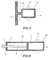
- the fluid accumulator displayed in Figure 1 , comprises a reservoir 1 for receiving the fluid, for example a gas or a liquid.
- the reservoir is surrounded longitudinally by a side wall 2 and contains at opposite ends of the side wall first and second end walls 3 and 4.
- the reservoir may have any desired shape, and can be, for example, cylinder-shaped or beam-shaped or have any other shape depending on the desired application.
- the side wall 2 and the end walls 3 and 4 are made of a composite, i.e. a fibrous reinforced plastic.
- the side wall 2 comprises a first expendable side wall portion 2A.
- the first side wall portion is preferably made of an elastically deformable, reversibly expandable plastic material.
- the side wall 2 also comprises a second side wall portion 2B that displays reduced expansibility.
- the second side wall portion can be made of the same plastic material, but will usually be made of a plastic with reduced elastic transformability and expansibility.
- the less expandable part is made of a plastic with reduced elasticity and transformability and/or the fibres are applied in a greater density.
- the flexibility and elasticity can also be controlled by executing the non-expandable part 2B with a greater thickness than the first expandable part 2A. It is possible to control the elasticity by using a different fibrous reinforcement material in the first and second side wall portions. It is also possible, during the "filament winding", to apply the fibres crosswise, at an angle of less than 90° with respect to the axis of the reservoir 2 and to use a different winding method in the first and second part.
- the end walls 3 and 4 can be manufactured in a mould, from non elastically deformable plastic, for example an epoxy resin or a polyester, provided with fibrous reinforcement material. Both the plastic and the fibrous reinforcement material may be the same as, or different from the material of which the wall 2 of the reservoir is made.
- the end walls may be attached to the side wall 2 in several ways, for example by means of gluing with an epoxy glue, or they may be part of them. This will usually depend on the manufacturing technique that is used.
- one or both end walls 3 and 4 may also be made of elastically deformable material, for example of a polyurethane elastomer.
- the end wall 3 may also be provided with a connection 5 for connecting a supply line 6.
- the cylinder shell 2 in one piece with the end walls 3 and 4 or not, is made by "braiding” in stead of "filament winding".
- the cylinder shell 2 is manufactured by a combination of filament winding and pultrusion, i.e. by the so-called pullwinding or by a combination of braiding and pultrusion.
- the end walls 3 and 4 are usually made separately.
- Figure 2 shows the fluid accumulator described above, that is used in an hydraulic suspension with built-in accumulator.
- a piston 7 is movable to and from the opposite end wall 4.
- a piston rod 8 is fixed to piston 7.
- the non expandable side wall portion 2B is executed longer and extends over the full travel of the piston 7.
- the expandable side wall portion 2A is located between the end wall 4 and the piston 7 in maximum inserted position.
- the piston 7, if so desired in one piece with the piston rod 8, is made of composite material in a mould, but it can also be made by filament winding or braiding.
- the end of the cylinder shell 2 through which the piston rod 8 extends outward is closed by an first end wall 3 with openings 10 that forms a guide for the piston rod 8.
- the first end wall 3 is preferably also made of composite material and glued to the cylinder shell 2 or is made as a whole with the cylinder shell 2 by "filament winding" or "braiding".
- the accumulator of this invention is suitable for use with various types of fluids, for example water, oil or every other liquid, or a gas.
- various types of fluids for example water, oil or every other liquid, or a gas.
- the expansibility of the first side wall portion 2A is subject to less demands.
- the suspension may be used in vehicles, as a shock absorber, or as dampener for absorbing shocks in machines or for tempering motion in cranes.
Landscapes
- Engineering & Computer Science (AREA)
- General Engineering & Computer Science (AREA)
- Mechanical Engineering (AREA)
- Physics & Mathematics (AREA)
- Fluid Mechanics (AREA)
- Supply Devices, Intensifiers, Converters, And Telemotors (AREA)
- Moulding By Coating Moulds (AREA)
Claims (14)
- Fluidspeicher, der sich zur Verwendung in einer hydraulischen oder pneumatischen Federung mit eingebautem Speicher oder Kompensator, einem Stoßdämpfer, einem Hydraulikzylinder zum Dämpfen von Bewegungen usw. eignet, umfassend einen verschließbaren Behälter (1) zum Aufnehmen eines Fluids unter einem Arbeitsdruck und eine Umschließungswand (2, 3, 4), welche den Behälter (1) umschließt, wobei der Behälter (1) durch eine Seitenwand (2) sowie eine erste und eine zweite Endwand (3, 4) an entgegengesetzten Seiten der Seitenwand umschlossen wird, wobei die Seitenwand (2) in Längsrichtung mindestens einen ersten Seitenwandabschnitt (2A) umfasst, der einen ersten Abschnitt des Behälters (1) umgibt, wobei der erste Seitenwandabschnitt aus einem ersten Verbundstoff hergestellt ist, wobei Faserverstärkungsmaterial in einer ersten Dichte aufgebracht ist, und der erste Seitenwandabschnitt (2A) unter dem Arbeitsdruck elastisch verformbar ist, derart, dass infolge der Ausdehnung des elastisch verformbaren ersten Wandabschnitts der Speicher eine variable Menge Fluid enthalten kann, dadurch gekennzeichnet, dass die Seitenwand (2) ferner in der Längsrichtung mindestens einen zweiten Seitenwandabschnitt (2B) umfasst, der einen zweiten Abschnitt des Behälters umgibt, der sich von dem ersten Abschnitt des Behälters unterscheidet, wobei der zweite Seitenwandabschnitt (2B) aus einem zweiten Verbundstoff mit in einer zweiten Dichte aufgebrachtem Faserverstärkungsmaterial hergestellt ist, dass die Dichtewerte des Faserverstärkungsmaterials in den ersten und den zweiten Wandabschnitten (2A, 2B) voneinander verschieden sind, dass der zweite Seitenwandabschnitt (2B) unter dem Arbeitsdruck weniger elastisch verformbar als der erste Seitenwandabschnitt (2A) ist, und dass zwischen den entgegengesetzten Endwänden ein Kolben (7) beweglich angebracht ist, um sich zu der zweiten Endwand (4) hin und von dieser weg zu bewegen, wobei der erste Seitenwandabschnitt (2A) zwischen der zweiten Endwand (4) und dem Kolben (7) angeordnet ist, wenn sich der Kolben in einer Position des maximalen Hubs in Richtung der zweiten Endwand (4) befindet.
- Fluidspeicher nach Anspruch 1, dadurch gekennzeichnet, dass die Wand (2, 3, 4) zur Gänze aus einem faserverstärktem Verbundstoff hergestellt ist, wobei der Verbundstoff einen Kunststoff enthält und der Kunststoff des ersten Seitenwandabschnitts (2A) ein elastischer Kunststoff ist, der vorgesehen ist, um sich unter Druck reversibel zu dehnen.
- Fluidspeicher nach Anspruch 1 oder 2, dadurch gekennzeichnet, dass der erste Verbundstoff einen ersten Kunststoff enthält und der zweite Verbundstoff einen zweiten Kunststoff enthält, welcher verglichen mit dem ersten Kunststoff eine andere elastische Verformbarkeit aufweist.
- Fluidspeicher nach einem beliebigen der Ansprüche 1 bis 3, dadurch gekennzeichnet, dass der zweite Seitenwandabschnitt (2B) verglichen mit dem ersten Seitenwandabschnitt (2A) eine größere Dicke aufweist.
- Fluidspeicher nach einem beliebigen der Ansprüche 1 bis 4, dadurch gekennzeichnet, dass die Fasern des Faserverstärkungsmaterials in dem ersten und dem zweiten Seitenwandabschnitt (2A, 2B) in verschiedenen Winkeln in Bezug auf eine Längsachse des Behälters (1) ausgerichtet sind.
- Fluidspeicher nach Anspruch 5, dadurch gekennzeichnet, dass der Winkel kleiner als 90° ist.
- Fluidspeicher nach einem beliebigen der Ansprüche 1-6, dadurch gekennzeichnet, dass das Faserverstärkungsmaterial, das in dem ersten Seitenwandabschnitt (2A) aufgebracht ist, Glasfasern sind.
- Fluidspeicher nach einem beliebigen der Ansprüche 1-7, dadurch gekennzeichnet, dass das Faserverstärkungsmaterial, das in dem zweiten Seitenwandabschnitt (2B) aufgebracht ist, Kohlefasern oder Polyesterfasern, vorzugsweise Aramidfasern, sind.
- Fluidspeicher nach einem beliebigen der Ansprüche 1-8, dadurch gekennzeichnet, dass der erste und/oder der zweite Verbundstoff ein Vinylesterharz enthält.
- Fluidspeicher nach Anspruch 1, dadurch gekennzeichnet, dass der Kolben (7) aus einem faserverstärkten Verbundstoff hergestellt ist.
- Fluidspeicher nach einem beliebigen der Ansprüche 1 bis 10, dadurch gekennzeichnet, dass die Wand (2, 3, 4) durch Filamentwickeln, Flechten, eine Kombination aus Filamentwickeln und Pultrusion, Pullwinding, eine Kombination aus Flechten und Pultrusion hergestellt wird.
- Fluidspeicher nach einem beliebigen der Ansprüche 1-11, dadurch gekennzeichnet, dass der erste und der zweite Seitenwandabschnitt (2A, 2B) unter Anwendung verschiedener Verfahren hergestellt werden.
- Fluidspeicher nach einem beliebigen der Ansprüche 1-12, dadurch gekennzeichnet, dass der Behälter zylinderförmig ist.
- Verwendung des Fluidspeichers gemäß einem beliebigen der Ansprüche 1-13 in einer hydraulischen oder pneumatischen Federung mit eingebautem Speicher oder Kompensator, einem Stoßdämpfer oder einem Hydraulikzylinder zum Dämpfen von Bewegungen.
Priority Applications (1)
| Application Number | Priority Date | Filing Date | Title |
|---|---|---|---|
| EP20100184714 EP2299126A1 (de) | 2002-04-30 | 2003-04-30 | Druckmittelspeicher |
Applications Claiming Priority (3)
| Application Number | Priority Date | Filing Date | Title |
|---|---|---|---|
| BE200200291 | 2002-04-30 | ||
| BE2002/0291A BE1014807A5 (nl) | 2002-04-30 | 2002-04-30 | Fluidumaccumulator en werkwijze voor het vervaardigen ervan. |
| PCT/BE2003/000077 WO2003093680A1 (en) | 2002-04-30 | 2003-04-30 | Fluid accumulator |
Related Child Applications (1)
| Application Number | Title | Priority Date | Filing Date |
|---|---|---|---|
| EP10184714.3 Division-Into | 2010-09-30 |
Publications (2)
| Publication Number | Publication Date |
|---|---|
| EP1523625A1 EP1523625A1 (de) | 2005-04-20 |
| EP1523625B1 true EP1523625B1 (de) | 2011-10-05 |
Family
ID=29274681
Family Applications (2)
| Application Number | Title | Priority Date | Filing Date |
|---|---|---|---|
| EP20100184714 Withdrawn EP2299126A1 (de) | 2002-04-30 | 2003-04-30 | Druckmittelspeicher |
| EP03722103A Expired - Lifetime EP1523625B1 (de) | 2002-04-30 | 2003-04-30 | Druckmittelspeicher |
Family Applications Before (1)
| Application Number | Title | Priority Date | Filing Date |
|---|---|---|---|
| EP20100184714 Withdrawn EP2299126A1 (de) | 2002-04-30 | 2003-04-30 | Druckmittelspeicher |
Country Status (8)
| Country | Link |
|---|---|
| US (1) | US7048009B2 (de) |
| EP (2) | EP2299126A1 (de) |
| CN (1) | CN1650108A (de) |
| AT (1) | ATE527451T1 (de) |
| AU (1) | AU2003236036A1 (de) |
| BE (1) | BE1014807A5 (de) |
| CA (1) | CA2484138C (de) |
| WO (1) | WO2003093680A1 (de) |
Families Citing this family (16)
| Publication number | Priority date | Publication date | Assignee | Title |
|---|---|---|---|---|
| US7614568B2 (en) * | 2000-08-24 | 2009-11-10 | Microlin, Llc | Device employing gas generating cell for facilitating controlled release of fluid into ambient environment |
| AU2006242425B2 (en) | 2005-04-29 | 2010-06-10 | Hendrickson International Corporation | Heavy-duty vehicle axle/suspension system |
| DE102005052402B4 (de) * | 2005-10-31 | 2012-03-01 | Faurecia Innenraum Systeme Gmbh | Energieabsorptionskörper, Kraftfahrzeug-Innenverkleidungsteil und Querträger für ein Kraftfahrzeug |
| US7493916B2 (en) * | 2005-12-12 | 2009-02-24 | Bosch Rexroth Corporation | Pressure vessel with accumulator isolation device |
| ATE552160T1 (de) | 2006-09-15 | 2012-04-15 | Groep Stevens Int Nv | Verbundanhänger |
| US8113390B2 (en) * | 2007-04-18 | 2012-02-14 | Microlin, Llc | Gas generation dispenser apparatus and method for on-demand fluid delivery |
| EP2058527A3 (de) * | 2007-11-08 | 2012-05-30 | Parker-Hannifin Corporation | Leichter, reparierbarer Hochdruckkolbenspeicher aus Verbundwerkstoff mit Gleitflansch |
| EP2060797A3 (de) * | 2007-11-13 | 2012-11-14 | Parker-Hannifin Corporation | Leichter, reparierbarer, mehrteiliger Hochdruckkolbenspeicher mit Zugstange |
| US20100176214A1 (en) * | 2009-01-13 | 2010-07-15 | Joshi Ashok V | Greeting card fragrance delivery system |
| MX2012004066A (es) * | 2009-10-05 | 2012-06-08 | Bosch Gmbh Robert | Sistema de almacenamiento de energia que incluye un ensamble de acumulador expansible y deposito. |
| WO2012000481A2 (de) | 2010-06-29 | 2012-01-05 | Schaeffler Technologies Gmbh & Co. Kg | Verfahren zur durchführung eines volumenausgleichs an einem doppelkupplungsgetriebe mit hydrostatischem einrücksystem |
| EP2714102B1 (de) | 2011-06-03 | 2018-10-10 | Microlin, LLC | Vorrichtung zur abgabe flüchtiger flüssigkeiten in eine gasförmige umgebung |
| DE102011109362A1 (de) * | 2011-08-04 | 2013-02-07 | Thyssen Krupp Bilstein Suspension GmbH | Stoßdämpfer für ein Fahrzeug in Leichtbauweise |
| US9150072B2 (en) | 2013-11-14 | 2015-10-06 | Hendrickson Usa, L.L.C. | Heavy-duty vehicle axle/suspension system with composite beam |
| DE102019205294A1 (de) * | 2019-04-12 | 2020-10-15 | Robert Bosch Gmbh | Hydraulisch betätigte Untersee-Klemmzylinder mit Krafthaltung |
| CN113883106B (zh) * | 2021-10-12 | 2022-06-03 | 燕山大学 | 自变容弹性液压油箱及其控制方法 |
Family Cites Families (18)
| Publication number | Priority date | Publication date | Assignee | Title |
|---|---|---|---|---|
| US260143A (en) | 1882-06-27 | wallace | ||
| FR951889A (fr) * | 1947-08-02 | 1949-11-04 | Soc Fr Regulateurs Arca | Procédé de fabrication de membranes tubulaires |
| DE932949C (de) * | 1950-09-07 | 1955-09-12 | Albert Dillenburger | Hydraulischer Teleskop-Stossdaempfer, insbesondere fuer Kraftfahrzeuge |
| FR1060812A (fr) * | 1951-11-19 | 1954-04-06 | Amortisseurs hydrauliques télescopiques de suspension | |
| US3084717A (en) * | 1957-08-28 | 1963-04-09 | Howard M Purcell | Piston type accumulator with flexible cylinder wall |
| NL6918558A (de) * | 1969-11-11 | 1971-05-13 | ||
| JPS5842822B2 (ja) | 1977-10-15 | 1983-09-22 | 株式会社カクイチ製作所 | 補強材を埋設した折り畳み可能な合成樹脂ホ−スの製造方法 |
| US4749071A (en) | 1982-04-22 | 1988-06-07 | Tayco Developments, Inc. | Fluid energy absorber device with composite plastic casing |
| FR2540603B1 (fr) * | 1983-02-08 | 1988-04-15 | Olaer Ind Sa | Reservoir de pression a double paroi |
| US4738339A (en) * | 1985-03-08 | 1988-04-19 | Tayco Developments, Inc. | Energy absorber device with composite plastic casing having high strength inner cylinder |
| SE8501793L (sv) * | 1985-04-12 | 1986-10-13 | Atlas Copco Ab | Vetskeackumulator och hydrauliskt slagverk med en sadan |
| IT1185613B (it) | 1985-05-30 | 1987-11-12 | Magnaghi Cleodinamica Spa | Accumulatore di pressione gas-olio con struttura in materiali compositi per circuiti idraulici di velivoli |
| US4777869A (en) * | 1986-03-28 | 1988-10-18 | Pneumo Abex Corporation | Fluid actuator including a composite piston rod |
| US6039078A (en) * | 1989-09-22 | 2000-03-21 | Tamari; Yehuda | Inline extracorporeal reservoir and pressure isolator |
| DE4035785C2 (de) * | 1990-11-10 | 1994-09-08 | Bosch Gmbh Robert | Blasenspeicher |
| US5368073A (en) * | 1993-10-07 | 1994-11-29 | Essef Corporation | Hydropneumatic pressure vessel having an improved diaphragm assembly |
| US5638868A (en) * | 1996-06-05 | 1997-06-17 | Valcor Engineering | Accumulator |
| DE19917481A1 (de) * | 1999-04-17 | 2000-10-19 | Festo Ag & Co | Betätigungseinrichtung |
-
2002
- 2002-04-30 BE BE2002/0291A patent/BE1014807A5/nl active
-
2003
- 2003-04-30 US US10/512,973 patent/US7048009B2/en not_active Expired - Fee Related
- 2003-04-30 AT AT03722103T patent/ATE527451T1/de not_active IP Right Cessation
- 2003-04-30 AU AU2003236036A patent/AU2003236036A1/en not_active Abandoned
- 2003-04-30 WO PCT/BE2003/000077 patent/WO2003093680A1/en not_active Ceased
- 2003-04-30 CA CA2484138A patent/CA2484138C/en not_active Expired - Fee Related
- 2003-04-30 EP EP20100184714 patent/EP2299126A1/de not_active Withdrawn
- 2003-04-30 EP EP03722103A patent/EP1523625B1/de not_active Expired - Lifetime
- 2003-04-30 CN CNA038096242A patent/CN1650108A/zh active Pending
Also Published As
| Publication number | Publication date |
|---|---|
| AU2003236036A1 (en) | 2003-11-17 |
| CN1650108A (zh) | 2005-08-03 |
| US20050166984A1 (en) | 2005-08-04 |
| BE1014807A5 (nl) | 2004-04-06 |
| ATE527451T1 (de) | 2011-10-15 |
| EP2299126A1 (de) | 2011-03-23 |
| CA2484138C (en) | 2011-12-13 |
| CA2484138A1 (en) | 2003-11-13 |
| US7048009B2 (en) | 2006-05-23 |
| EP1523625A1 (de) | 2005-04-20 |
| WO2003093680A1 (en) | 2003-11-13 |
Similar Documents
| Publication | Publication Date | Title |
|---|---|---|
| EP1523625B1 (de) | Druckmittelspeicher | |
| US6830286B2 (en) | Fiber composite crash structure | |
| US8608232B2 (en) | Crash protection element, its use and method for its manufacture | |
| US5118086A (en) | Elastomeric spring with non-linear force/deflection characteristics | |
| US10683907B2 (en) | Spring | |
| US6328294B1 (en) | Elastomeric spring system | |
| US20150158361A1 (en) | Four-point link | |
| US10240654B2 (en) | Hybrid spring device | |
| GB2375502A (en) | Moulded composite transverse leaf spring | |
| EP0446476B1 (de) | Abrollkolben für den Rollbalg einer Rollbalg-Luftfeder | |
| WO2018148139A1 (en) | Composite sporting equipment | |
| US20150050441A1 (en) | Structural component semi-finished part for producing a fiber-reinforced structural component as well as structural component and method for the production thereof | |
| US20140091504A1 (en) | Gas spring assembly and method | |
| JP2013504464A (ja) | 車両用のスタビライザ及びその製造の方法 | |
| US4634399A (en) | Structural component for transmitting torque | |
| DE102018216717A1 (de) | Luftfederbein mit einem Kunststoff-Luftfederdeckel aus Thermoplast | |
| CN113681931A (zh) | 基于预浸料成型的复合材料板簧本体的制备方法 | |
| CN108277702B (zh) | 一种低应力高阻尼铁路扣件弹条 | |
| WO2019020703A1 (de) | Verfahren zum herstellen einer schraubenfeder | |
| CN212297546U (zh) | 一种新型减振换挡杆及含有该换挡杆的车辆 | |
| CN1239197A (zh) | 波纹管液压减振器 | |
| CN212564205U (zh) | 一种基于气囊技术的柔性减震器 | |
| CA1199650A (en) | Composite leaf spring | |
| KR102391001B1 (ko) | 복합재 코일 스프링 및 그 제조방법 | |
| GB2338996A (en) | Sealing membrane for a vehicle suspension vibration damper |
Legal Events
| Date | Code | Title | Description |
|---|---|---|---|
| PUAI | Public reference made under article 153(3) epc to a published international application that has entered the european phase |
Free format text: ORIGINAL CODE: 0009012 |
|
| 17P | Request for examination filed |
Effective date: 20050214 |
|
| AK | Designated contracting states |
Kind code of ref document: A1 Designated state(s): AT BE BG CH CY CZ DE DK EE ES FI FR GB GR HU IE IT LI LU MC NL PT RO SE SI SK TR |
|
| AX | Request for extension of the european patent |
Extension state: AL LT LV MK |
|
| 17Q | First examination report despatched |
Effective date: 20070213 |
|
| GRAP | Despatch of communication of intention to grant a patent |
Free format text: ORIGINAL CODE: EPIDOSNIGR1 |
|
| GRAS | Grant fee paid |
Free format text: ORIGINAL CODE: EPIDOSNIGR3 |
|
| GRAA | (expected) grant |
Free format text: ORIGINAL CODE: 0009210 |
|
| AK | Designated contracting states |
Kind code of ref document: B1 Designated state(s): AT BE BG CH CY CZ DE DK EE ES FI FR GB GR HU IE IT LI LU MC NL PT RO SE SI SK TR |
|
| REG | Reference to a national code |
Ref country code: GB Ref legal event code: FG4D |
|
| REG | Reference to a national code |
Ref country code: CH Ref legal event code: EP |
|
| REG | Reference to a national code |
Ref country code: IE Ref legal event code: FG4D |
|
| REG | Reference to a national code |
Ref country code: DE Ref legal event code: R096 Ref document number: 60338620 Country of ref document: DE Effective date: 20111229 |
|
| REG | Reference to a national code |
Ref country code: NL Ref legal event code: T3 |
|
| PG25 | Lapsed in a contracting state [announced via postgrant information from national office to epo] |
Ref country code: SI Free format text: LAPSE BECAUSE OF FAILURE TO SUBMIT A TRANSLATION OF THE DESCRIPTION OR TO PAY THE FEE WITHIN THE PRESCRIBED TIME-LIMIT Effective date: 20111005 |
|
| REG | Reference to a national code |
Ref country code: AT Ref legal event code: MK05 Ref document number: 527451 Country of ref document: AT Kind code of ref document: T Effective date: 20111005 |
|
| PGFP | Annual fee paid to national office [announced via postgrant information from national office to epo] |
Ref country code: FR Payment date: 20120307 Year of fee payment: 10 |
|
| PG25 | Lapsed in a contracting state [announced via postgrant information from national office to epo] |
Ref country code: PT Free format text: LAPSE BECAUSE OF FAILURE TO SUBMIT A TRANSLATION OF THE DESCRIPTION OR TO PAY THE FEE WITHIN THE PRESCRIBED TIME-LIMIT Effective date: 20120206 Ref country code: GR Free format text: LAPSE BECAUSE OF FAILURE TO SUBMIT A TRANSLATION OF THE DESCRIPTION OR TO PAY THE FEE WITHIN THE PRESCRIBED TIME-LIMIT Effective date: 20120106 Ref country code: SE Free format text: LAPSE BECAUSE OF FAILURE TO SUBMIT A TRANSLATION OF THE DESCRIPTION OR TO PAY THE FEE WITHIN THE PRESCRIBED TIME-LIMIT Effective date: 20111005 |
|
| PG25 | Lapsed in a contracting state [announced via postgrant information from national office to epo] |
Ref country code: CY Free format text: LAPSE BECAUSE OF FAILURE TO SUBMIT A TRANSLATION OF THE DESCRIPTION OR TO PAY THE FEE WITHIN THE PRESCRIBED TIME-LIMIT Effective date: 20111005 |
|
| PG25 | Lapsed in a contracting state [announced via postgrant information from national office to epo] |
Ref country code: BG Free format text: LAPSE BECAUSE OF FAILURE TO SUBMIT A TRANSLATION OF THE DESCRIPTION OR TO PAY THE FEE WITHIN THE PRESCRIBED TIME-LIMIT Effective date: 20120105 Ref country code: DK Free format text: LAPSE BECAUSE OF FAILURE TO SUBMIT A TRANSLATION OF THE DESCRIPTION OR TO PAY THE FEE WITHIN THE PRESCRIBED TIME-LIMIT Effective date: 20111005 Ref country code: EE Free format text: LAPSE BECAUSE OF FAILURE TO SUBMIT A TRANSLATION OF THE DESCRIPTION OR TO PAY THE FEE WITHIN THE PRESCRIBED TIME-LIMIT Effective date: 20111005 Ref country code: SK Free format text: LAPSE BECAUSE OF FAILURE TO SUBMIT A TRANSLATION OF THE DESCRIPTION OR TO PAY THE FEE WITHIN THE PRESCRIBED TIME-LIMIT Effective date: 20111005 Ref country code: CZ Free format text: LAPSE BECAUSE OF FAILURE TO SUBMIT A TRANSLATION OF THE DESCRIPTION OR TO PAY THE FEE WITHIN THE PRESCRIBED TIME-LIMIT Effective date: 20111005 |
|
| PGFP | Annual fee paid to national office [announced via postgrant information from national office to epo] |
Ref country code: NL Payment date: 20120224 Year of fee payment: 10 |
|
| PLBE | No opposition filed within time limit |
Free format text: ORIGINAL CODE: 0009261 |
|
| STAA | Information on the status of an ep patent application or granted ep patent |
Free format text: STATUS: NO OPPOSITION FILED WITHIN TIME LIMIT |
|
| PG25 | Lapsed in a contracting state [announced via postgrant information from national office to epo] |
Ref country code: IT Free format text: LAPSE BECAUSE OF FAILURE TO SUBMIT A TRANSLATION OF THE DESCRIPTION OR TO PAY THE FEE WITHIN THE PRESCRIBED TIME-LIMIT Effective date: 20111005 Ref country code: RO Free format text: LAPSE BECAUSE OF FAILURE TO SUBMIT A TRANSLATION OF THE DESCRIPTION OR TO PAY THE FEE WITHIN THE PRESCRIBED TIME-LIMIT Effective date: 20111005 |
|
| PGFP | Annual fee paid to national office [announced via postgrant information from national office to epo] |
Ref country code: GB Payment date: 20120419 Year of fee payment: 10 |
|
| 26N | No opposition filed |
Effective date: 20120706 |
|
| REG | Reference to a national code |
Ref country code: DE Ref legal event code: R097 Ref document number: 60338620 Country of ref document: DE Effective date: 20120706 |
|
| PG25 | Lapsed in a contracting state [announced via postgrant information from national office to epo] |
Ref country code: MC Free format text: LAPSE BECAUSE OF NON-PAYMENT OF DUE FEES Effective date: 20120430 |
|
| REG | Reference to a national code |
Ref country code: CH Ref legal event code: PL |
|
| PG25 | Lapsed in a contracting state [announced via postgrant information from national office to epo] |
Ref country code: CH Free format text: LAPSE BECAUSE OF NON-PAYMENT OF DUE FEES Effective date: 20120430 Ref country code: LI Free format text: LAPSE BECAUSE OF NON-PAYMENT OF DUE FEES Effective date: 20120430 Ref country code: AT Free format text: LAPSE BECAUSE OF FAILURE TO SUBMIT A TRANSLATION OF THE DESCRIPTION OR TO PAY THE FEE WITHIN THE PRESCRIBED TIME-LIMIT Effective date: 20111005 |
|
| PG25 | Lapsed in a contracting state [announced via postgrant information from national office to epo] |
Ref country code: ES Free format text: LAPSE BECAUSE OF FAILURE TO SUBMIT A TRANSLATION OF THE DESCRIPTION OR TO PAY THE FEE WITHIN THE PRESCRIBED TIME-LIMIT Effective date: 20120116 Ref country code: IE Free format text: LAPSE BECAUSE OF NON-PAYMENT OF DUE FEES Effective date: 20120430 |
|
| PG25 | Lapsed in a contracting state [announced via postgrant information from national office to epo] |
Ref country code: FI Free format text: LAPSE BECAUSE OF FAILURE TO SUBMIT A TRANSLATION OF THE DESCRIPTION OR TO PAY THE FEE WITHIN THE PRESCRIBED TIME-LIMIT Effective date: 20111005 |
|
| REG | Reference to a national code |
Ref country code: NL Ref legal event code: V1 Effective date: 20131101 |
|
| GBPC | Gb: european patent ceased through non-payment of renewal fee |
Effective date: 20130430 |
|
| PG25 | Lapsed in a contracting state [announced via postgrant information from national office to epo] |
Ref country code: GB Free format text: LAPSE BECAUSE OF NON-PAYMENT OF DUE FEES Effective date: 20130430 |
|
| REG | Reference to a national code |
Ref country code: FR Ref legal event code: ST Effective date: 20131231 |
|
| PG25 | Lapsed in a contracting state [announced via postgrant information from national office to epo] |
Ref country code: NL Free format text: LAPSE BECAUSE OF NON-PAYMENT OF DUE FEES Effective date: 20131101 Ref country code: FR Free format text: LAPSE BECAUSE OF NON-PAYMENT OF DUE FEES Effective date: 20130430 |
|
| PG25 | Lapsed in a contracting state [announced via postgrant information from national office to epo] |
Ref country code: TR Free format text: LAPSE BECAUSE OF FAILURE TO SUBMIT A TRANSLATION OF THE DESCRIPTION OR TO PAY THE FEE WITHIN THE PRESCRIBED TIME-LIMIT Effective date: 20111005 |
|
| PG25 | Lapsed in a contracting state [announced via postgrant information from national office to epo] |
Ref country code: LU Free format text: LAPSE BECAUSE OF NON-PAYMENT OF DUE FEES Effective date: 20120430 |
|
| PG25 | Lapsed in a contracting state [announced via postgrant information from national office to epo] |
Ref country code: HU Free format text: LAPSE BECAUSE OF FAILURE TO SUBMIT A TRANSLATION OF THE DESCRIPTION OR TO PAY THE FEE WITHIN THE PRESCRIBED TIME-LIMIT Effective date: 20030430 |
|
| PGFP | Annual fee paid to national office [announced via postgrant information from national office to epo] |
Ref country code: BE Payment date: 20140630 Year of fee payment: 12 Ref country code: DE Payment date: 20140627 Year of fee payment: 12 |
|
| REG | Reference to a national code |
Ref country code: DE Ref legal event code: R119 Ref document number: 60338620 Country of ref document: DE |
|
| PG25 | Lapsed in a contracting state [announced via postgrant information from national office to epo] |
Ref country code: DE Free format text: LAPSE BECAUSE OF NON-PAYMENT OF DUE FEES Effective date: 20151103 |
|
| PG25 | Lapsed in a contracting state [announced via postgrant information from national office to epo] |
Ref country code: BE Free format text: LAPSE BECAUSE OF NON-PAYMENT OF DUE FEES Effective date: 20150430 |