EP1523616B1 - Procede d'amelioration de la transmission de couple d'une machine a combustion interne multicylindre alternative a quatre temps - Google Patents
Procede d'amelioration de la transmission de couple d'une machine a combustion interne multicylindre alternative a quatre temps Download PDFInfo
- Publication number
- EP1523616B1 EP1523616B1 EP03765063A EP03765063A EP1523616B1 EP 1523616 B1 EP1523616 B1 EP 1523616B1 EP 03765063 A EP03765063 A EP 03765063A EP 03765063 A EP03765063 A EP 03765063A EP 1523616 B1 EP1523616 B1 EP 1523616B1
- Authority
- EP
- European Patent Office
- Prior art keywords
- cylinders
- fired
- cylinder
- gas
- gas exchange
- Prior art date
- Legal status (The legal status is an assumption and is not a legal conclusion. Google has not performed a legal analysis and makes no representation as to the accuracy of the status listed.)
- Expired - Lifetime
Links
- 238000000034 method Methods 0.000 title claims abstract description 17
- 230000006835 compression Effects 0.000 claims abstract description 17
- 238000007906 compression Methods 0.000 claims abstract description 17
- 238000010304 firing Methods 0.000 claims abstract description 16
- 238000002485 combustion reaction Methods 0.000 claims abstract description 15
- 239000000446 fuel Substances 0.000 claims abstract description 9
- 230000001960 triggered effect Effects 0.000 claims abstract 4
- 230000008859 change Effects 0.000 claims description 4
- 230000001419 dependent effect Effects 0.000 claims 1
- 230000009849 deactivation Effects 0.000 description 10
- 230000007704 transition Effects 0.000 description 6
- 238000010586 diagram Methods 0.000 description 5
- 230000006870 function Effects 0.000 description 4
- 230000008901 benefit Effects 0.000 description 2
- 230000000694 effects Effects 0.000 description 2
- 206010038743 Restlessness Diseases 0.000 description 1
- 230000015572 biosynthetic process Effects 0.000 description 1
- 239000003990 capacitor Substances 0.000 description 1
- 238000009841 combustion method Methods 0.000 description 1
- 238000012937 correction Methods 0.000 description 1
- 230000007423 decrease Effects 0.000 description 1
- 230000003111 delayed effect Effects 0.000 description 1
- 238000009499 grossing Methods 0.000 description 1
- 230000000737 periodic effect Effects 0.000 description 1
- 230000008569 process Effects 0.000 description 1
- 230000008093 supporting effect Effects 0.000 description 1
Images


Classifications
-
- F—MECHANICAL ENGINEERING; LIGHTING; HEATING; WEAPONS; BLASTING
- F02—COMBUSTION ENGINES; HOT-GAS OR COMBUSTION-PRODUCT ENGINE PLANTS
- F02D—CONTROLLING COMBUSTION ENGINES
- F02D13/00—Controlling the engine output power by varying inlet or exhaust valve operating characteristics, e.g. timing
- F02D13/02—Controlling the engine output power by varying inlet or exhaust valve operating characteristics, e.g. timing during engine operation
- F02D13/0203—Variable control of intake and exhaust valves
-
- F—MECHANICAL ENGINEERING; LIGHTING; HEATING; WEAPONS; BLASTING
- F01—MACHINES OR ENGINES IN GENERAL; ENGINE PLANTS IN GENERAL; STEAM ENGINES
- F01L—CYCLICALLY OPERATING VALVES FOR MACHINES OR ENGINES
- F01L13/00—Modifications of valve-gear to facilitate reversing, braking, starting, changing compression ratio, or other specific operations
- F01L13/0005—Deactivating valves
-
- F—MECHANICAL ENGINEERING; LIGHTING; HEATING; WEAPONS; BLASTING
- F01—MACHINES OR ENGINES IN GENERAL; ENGINE PLANTS IN GENERAL; STEAM ENGINES
- F01L—CYCLICALLY OPERATING VALVES FOR MACHINES OR ENGINES
- F01L9/00—Valve-gear or valve arrangements actuated non-mechanically
- F01L9/20—Valve-gear or valve arrangements actuated non-mechanically by electric means
-
- F—MECHANICAL ENGINEERING; LIGHTING; HEATING; WEAPONS; BLASTING
- F02—COMBUSTION ENGINES; HOT-GAS OR COMBUSTION-PRODUCT ENGINE PLANTS
- F02D—CONTROLLING COMBUSTION ENGINES
- F02D13/00—Controlling the engine output power by varying inlet or exhaust valve operating characteristics, e.g. timing
- F02D13/02—Controlling the engine output power by varying inlet or exhaust valve operating characteristics, e.g. timing during engine operation
- F02D13/06—Cutting-out cylinders
-
- F—MECHANICAL ENGINEERING; LIGHTING; HEATING; WEAPONS; BLASTING
- F02—COMBUSTION ENGINES; HOT-GAS OR COMBUSTION-PRODUCT ENGINE PLANTS
- F02D—CONTROLLING COMBUSTION ENGINES
- F02D17/00—Controlling engines by cutting out individual cylinders; Rendering engines inoperative or idling
- F02D17/02—Cutting-out
-
- F—MECHANICAL ENGINEERING; LIGHTING; HEATING; WEAPONS; BLASTING
- F02—COMBUSTION ENGINES; HOT-GAS OR COMBUSTION-PRODUCT ENGINE PLANTS
- F02D—CONTROLLING COMBUSTION ENGINES
- F02D41/00—Electrical control of supply of combustible mixture or its constituents
- F02D41/008—Controlling each cylinder individually
- F02D41/0087—Selective cylinder activation, i.e. partial cylinder operation
-
- F—MECHANICAL ENGINEERING; LIGHTING; HEATING; WEAPONS; BLASTING
- F01—MACHINES OR ENGINES IN GENERAL; ENGINE PLANTS IN GENERAL; STEAM ENGINES
- F01L—CYCLICALLY OPERATING VALVES FOR MACHINES OR ENGINES
- F01L2800/00—Methods of operation using a variable valve timing mechanism
-
- F—MECHANICAL ENGINEERING; LIGHTING; HEATING; WEAPONS; BLASTING
- F02—COMBUSTION ENGINES; HOT-GAS OR COMBUSTION-PRODUCT ENGINE PLANTS
- F02D—CONTROLLING COMBUSTION ENGINES
- F02D13/00—Controlling the engine output power by varying inlet or exhaust valve operating characteristics, e.g. timing
- F02D13/02—Controlling the engine output power by varying inlet or exhaust valve operating characteristics, e.g. timing during engine operation
- F02D13/0203—Variable control of intake and exhaust valves
- F02D13/0207—Variable control of intake and exhaust valves changing valve lift or valve lift and timing
-
- F—MECHANICAL ENGINEERING; LIGHTING; HEATING; WEAPONS; BLASTING
- F02—COMBUSTION ENGINES; HOT-GAS OR COMBUSTION-PRODUCT ENGINE PLANTS
- F02D—CONTROLLING COMBUSTION ENGINES
- F02D13/00—Controlling the engine output power by varying inlet or exhaust valve operating characteristics, e.g. timing
- F02D13/02—Controlling the engine output power by varying inlet or exhaust valve operating characteristics, e.g. timing during engine operation
- F02D13/0253—Fully variable control of valve lift and timing using camless actuation systems such as hydraulic, pneumatic or electromagnetic actuators, e.g. solenoid valves
-
- F—MECHANICAL ENGINEERING; LIGHTING; HEATING; WEAPONS; BLASTING
- F02—COMBUSTION ENGINES; HOT-GAS OR COMBUSTION-PRODUCT ENGINE PLANTS
- F02D—CONTROLLING COMBUSTION ENGINES
- F02D41/00—Electrical control of supply of combustible mixture or its constituents
- F02D41/0002—Controlling intake air
- F02D2041/001—Controlling intake air for engines with variable valve actuation
-
- F—MECHANICAL ENGINEERING; LIGHTING; HEATING; WEAPONS; BLASTING
- F02—COMBUSTION ENGINES; HOT-GAS OR COMBUSTION-PRODUCT ENGINE PLANTS
- F02D—CONTROLLING COMBUSTION ENGINES
- F02D41/00—Electrical control of supply of combustible mixture or its constituents
- F02D41/008—Controlling each cylinder individually
- F02D41/0082—Controlling each cylinder individually per groups or banks
-
- Y—GENERAL TAGGING OF NEW TECHNOLOGICAL DEVELOPMENTS; GENERAL TAGGING OF CROSS-SECTIONAL TECHNOLOGIES SPANNING OVER SEVERAL SECTIONS OF THE IPC; TECHNICAL SUBJECTS COVERED BY FORMER USPC CROSS-REFERENCE ART COLLECTIONS [XRACs] AND DIGESTS
- Y02—TECHNOLOGIES OR APPLICATIONS FOR MITIGATION OR ADAPTATION AGAINST CLIMATE CHANGE
- Y02T—CLIMATE CHANGE MITIGATION TECHNOLOGIES RELATED TO TRANSPORTATION
- Y02T10/00—Road transport of goods or passengers
- Y02T10/10—Internal combustion engine [ICE] based vehicles
- Y02T10/12—Improving ICE efficiencies
Definitions
- the invention Since in principle a cylinder deactivation at all engine speeds and at low load can mean a significant saving in consumption, the invention has for its object to provide a method for improving the torque curve, which also improved at least for four-cylinder four-stroke piston internal combustion engines, but also for higher cylinder numbers Torque curve results.
- a method for improving the torque curve on a multi-cylinder four-stroke piston internal combustion engine which has at least two pairs of cylinders with variably controllable gas exchange valves, wherein in each case a pair of cylinders consists of two cylinders which are assigned by a firing interval of 360 ° crank angle, and wherein via an engine control for a part load operation by switching off the fuel supply and acting on the gas exchange valves, the cylinder a cylinder pair are not fired, which is characterized in that for the partial load operation, the cylinders of the non-fired cylinder pair for setting a predetermined, affecting the torque curve compression height by appropriately driving the gas exchange valves record a predetermined amount of charge, and that for the duration of the partial load operation, the gas exchange valves of these cylinders be kept closed and only for influencing the amount of charge in each case in the region of the piston passage through the region of the bottom dead center, the associated gas inlet valve or Gasaus laßventils is opened briefly.
- the effect of the method according to the invention is that the charge quantity received by the non-fired cylinders when the gas exchange valves are held closed acts like a storage spring which is compressed from top dead center to top dead center during a piston movement and again from top dead center to bottom dead center during piston movement relaxed and thus gives off work on the piston.
- each associated gas inlet valves or gas outlet valves are opened briefly to the absorbed charge amount to influence, for example, to compensate for blow-by losses again, so that can be maintained with a predetermined optimum amount of charge, the above-described supporting effect by compression and expansion with closed gas exchange valves on the non-fired cylinders.
- the current torque curve is detected, for example via a sensor associated with the crankshaft, which is then taken into account as an actual value with a predetermined desired value which can also be stored as a characteristic map.
- a predetermined desired value which can also be stored as a characteristic map.
- the amount of charge which can be predetermined for the non-fired cylinders can either be formed via exhaust gas or else be formed via fresh air.
- the gas inlet valves of the non-fired cylinders are to be correspondingly actuated with the gas outlet valves closed.
- the gas exchange valves are to provide appropriate procedures for a fast-reacting transition in the transition from partial load to full load with connection of the non-fired valves.
- curve 2 represents the torque curve for the four-cylinder engine corresponding to Fig. 1, which results when a pair of cylinders, i. two cylinders are switched off with a firing interval of 360 degrees crank angle in such a way that fuel supply and ignition are turned off, the operation of the gas exchange valves, however, continues to take place in the normal power stroke.
- the curve reveals, results in a very uneven torque curve and thus a restless running of the reciprocating internal combustion engine.
- the intake valves are kept closed and sucked with the shutdown at the respective first downward movement of the pistons of this pair of cylinders in the intake stroke exhaust. Over the opening period, the amount of charge can be determined.
- the gas outlet valves are closed and during held closed during the entire duration of the shutdown phase, so that the amount of charge absorbed in the two non-fired cylinders of the deactivated cylinder pair is compressed in each case in the upward movement of the piston, whereby a negative torque is applied to the crankshaft, when the corresponding cylinder of the fired pair of cylinders passes through the expansion stroke ,
- the amount of charge taken in each case can expand, so that a positive torque acts on the crankshaft when the corresponding cylinder of the fired pair of cylinders passes through the compression stroke.
- Due to the predetermined firing interval of 360 ° of the mutually associated pairs of cylinders results in the corresponding firing order of the curve 3 in Fig. 2 shown much more uniform torque curve for the entire machine.
- fresh air can be specified in the same way. This only results in a different drive scheme for the actuation of the gas exchange valves.
- FIG. 3 the circuit diagram for the "exhaust operation" in a four-cylinder four-stroke piston internal combustion engine with a firing interval of 360 ° of the mutually associated pairs of cylinders in a firing order 1-3-4-2 is shown.
- the switch-off period isr marked by a frame.
- Fig. 4 is for the same, also characterized by a frame shutdown of power stroke 5 to Working cycle 15 the circuit diagram for the air compression shown.
- the fuel supply is shut off for the cylinder 3 already at the beginning of the suction cycle in the power stroke 5, so that (practically) only air is sucked in and the absorbed amount of charge from the power stroke 6 are compressed with closed gas exchange valves and can expand, so that for the transition to Full load operation for the power stroke 16 the gas outlet valve can be controlled in "normal operation".
- the shutdown of the control of the gas exchange valves is delayed accordingly.
- the fuel supply is turned off at the beginning of the power stroke 7, so that after the suction cycle with the power stroke 8, the gas exchange valves remain closed.
- the gas exchange valves with the power stroke 14 are already driven back in normal operation.
- a periodically changing torque to the crankshaft.
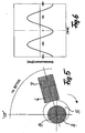
- This can be done, for example, in the form that, as shown in Fig. 5, is added to a mounted on the crankshaft 4 cam 5 via a plunger 6 and a storage spring 7, a corresponding force and re-introduced.
- the apex of the eccentricity is about -80 ° crank angle after the top dead center of the fired cylinder, so that during the expansion stroke of each fired cylinder, a portion of the energy is absorbed via the storage spring 7 and released again at the transition to the exhaust stroke.
- the cam of the cam 5 is designed so that the shown in Fig. 6 with the arrangement of FIG. 5 additionally applied torque curve is achieved.
- This additional applied torque curve has a negative moment during compression and expansion of the fired cylinders and due to the firing interval during compression and expansion of the deactivated cylinders a positive moment.
- an additional smoothing of the torque curve as shown by the curve 3.1 in FIG. 1, results.
- the spring force of the accumulator spring 7 is adjustable.
- the angle of maximum deflection, and thus the maximum cam lift, is to be selected on the crankshaft such that at this crankshaft position the fired cylinders have substantially completed compression and expansion. This is approximately given at an angle of 80 ° crank angle after TDC.
- Another possibility for additionally applying a periodically changing torque consists in the periodic torque operation of an electric machine connected to the reciprocating internal combustion engine and a corresponding energy store, which briefly absorbs the torque or briefly decreases a load and then releases it again.
- This is given for example by batteries or capacitors, which are connected to an electric machine, which can be operated both in generator and in engine operation.
- Closing the "sucking" valves at the beginning of the cylinder deactivation to a point in the vicinity of the bottom dead center leads to a high charge use of compressing and expanding cylinder on average without torque delivery.
- By closing the last open or “sucking" valves at a time before or after the bottom dead center the amount of charge and thus the compression height to be achieved in the disconnected, ie non-fired cylinders.
- a momentary opening and closing of one or more of the "sucking" valves at a time near bottom dead center causes an air or exhaust gas intake, thus compensating for the charge portion escaped from the cylinder by blow-by losses.
- the reloading of the cylinder charge to compensate for blow-by losses or even a change in the amount of charge can be done all 360 ° crank angle or even limited to every n th working game.
- the amount of charge required increases with the load of the fired cylinders.
- the measures described above for improving the torque curve in four-stroke piston internal combustion engines can be used accordingly for reciprocating internal combustion engines with 8, 12 or 16 cylinders.
- two pairs of cylinders are switched off in an eight-cylinder engine, three pairs of cylinders in a twelve-cylinder engine and four pairs of cylinders in a sixteen-cylinder engine, each having its top dead center at the same crank angle.
- the cylinders to be deactivated are cylinders with the same firing interval, which is twice as long as in full operation.
- the engine control can now be designed so that when exceeding a predetermined duration for the part-load operation, the cylinder deactivation switches from one pair of cylinders to the other pair of cylinders, so as to maintain a minimum temperature level for each pair of cylinders switched off, thus at the transition from part load operation to full load each pair of cylinders off as soon as possible reaches its operating temperature again.
Landscapes
- Engineering & Computer Science (AREA)
- Mechanical Engineering (AREA)
- General Engineering & Computer Science (AREA)
- Chemical & Material Sciences (AREA)
- Combustion & Propulsion (AREA)
- Output Control And Ontrol Of Special Type Engine (AREA)
- Pistons, Piston Rings, And Cylinders (AREA)
- Devices For Conveying Motion By Means Of Endless Flexible Members (AREA)
- Lubrication Of Internal Combustion Engines (AREA)
- Combustion Methods Of Internal-Combustion Engines (AREA)
- Electrical Control Of Air Or Fuel Supplied To Internal-Combustion Engine (AREA)
Claims (5)
- Procédé pour améliorer la courbe de couple d'un moteur à combustion interne multicylindres à quatre temps, présentant au moins deux paires de cylindres munies de soupapes d'échange des gaz à commande variable, chacune des paires de cylindres se composant de deux cylindres associés l'un à l'autre par un décalage d'allumage de 360° du vilebrequin, et dans lequel, via une commande de charge partielle du moteur par la coupure de l'arrivée du carburant et une action sur les soupapes d'échange des gaz, les cylindres d'une paire de cylindres ne sont pas enflammés, caractérisé en ce que pour le mode de charge partielle, les cylindres de la paire de cylindres non enflammée, pour la mise en place d'une compression prédéterminée agissant sur la courbe de couple, reçoivent par une commande correspondante des soupapes d'échange des gaz une quantité de charge prédéterminée, et en ce que pendant toute la durée du mode de charge partielle, les soupapes d'échange des gaz de ces cylindres sont maintenues fermées et que la soupape d'admission, respectivement la soupape d'échappement, des gaz associée n'est que brièvement ouverte dans la zone de course inférieure du piston passant par la zone de point mort bas pour influer sur la quantité de charge.
- Procédé selon la revendication 1, caractérisé en ce que la prédétermination de la quantité de charge est adaptée en fonction de la charge et/ou du régime et/ou de la courbe de couple par une commande correspondante des soupapes d'échange des gaz lors de la course du piston dans la zone du point mort bas.
- Procédé selon la revendication 1 ou 2, caractérisé en ce que pour former la courbe de couple, on applique en outre sur le vilebrequin un couple supplémentaire adapté aux cylindres enflammés.
- Procédé selon l'une des revendications 1 à 3, caractérisé en ce que dans le cas où l'on utilise les gaz d'échappement en tant que quantité de charge pouvant être prédéterminée pour la paire de cylindres à désactiver, lors de la transition entre le mode enflammé et le mode non enflammé, pendant la course d'admission des cylindres, les soupapes d'admission des gaz sont maintenues fermées et les soupapes d'échappement des gaz sont respectivement ouvertes, de telle sorte que les gaz d'échappement sont admis en tant que quantité de charge, et en ce que lors de la transition entre le mode non enflammé et le mode enflammé, les soupapes d'échange des gaz des cylindres non enflammés sont commandées dans le temps moteur normal avec une alternance de charge correspondant au mode pleine charge et que l'arrivée de carburant est actionnée conformément à la séquence d'allumage normale.
- Procédé selon l'une des revendications 1 à 3, caractérisé en ce que dans le cas où l'on utilise l'air en tant que quantité de charge pouvant être prédéterminée pour les cylindres de la paire de cylindres à désactiver, lors de la transition entre le mode enflammé et le mode non enflammé, les soupapes d'échappement des gaz sont maintenues fermées et les soupapes d'admission des gaz sont ouvertes lors de la course d'admission, de telle sorte que de l'air est admis en tant que quantité de charge, et en ce que lors de la transition entre le mode non enflammé et le mode enflammé, les soupapes d'échange des gaz des cylindres non enflammés sont commandées dans le temps moteur normal avec une alternance de charge correspondant au mode pleine charge et que l'arrivée de carburant est actionnée conformément à la séquence d'allumage normale.
Applications Claiming Priority (3)
| Application Number | Priority Date | Filing Date | Title |
|---|---|---|---|
| DE10233284 | 2002-07-23 | ||
| DE10233284A DE10233284A1 (de) | 2002-07-23 | 2002-07-23 | Verfahren zur Verbesserung des Drehmomentverlaufs an einer Mehrzylinder-Viertakt-Kolbenbrennkraftmaschine |
| PCT/EP2003/007915 WO2004009983A1 (fr) | 2002-07-23 | 2003-07-19 | Procede d'amelioration de la transmission de couple d'une machine a combustion interne multicylindre alternative a quatre temps |
Publications (2)
| Publication Number | Publication Date |
|---|---|
| EP1523616A1 EP1523616A1 (fr) | 2005-04-20 |
| EP1523616B1 true EP1523616B1 (fr) | 2006-09-06 |
Family
ID=30128237
Family Applications (1)
| Application Number | Title | Priority Date | Filing Date |
|---|---|---|---|
| EP03765063A Expired - Lifetime EP1523616B1 (fr) | 2002-07-23 | 2003-07-19 | Procede d'amelioration de la transmission de couple d'une machine a combustion interne multicylindre alternative a quatre temps |
Country Status (6)
| Country | Link |
|---|---|
| US (1) | US7028660B2 (fr) |
| EP (1) | EP1523616B1 (fr) |
| AT (1) | ATE338886T1 (fr) |
| AU (1) | AU2003254548A1 (fr) |
| DE (2) | DE10233284A1 (fr) |
| WO (1) | WO2004009983A1 (fr) |
Cited By (1)
| Publication number | Priority date | Publication date | Assignee | Title |
|---|---|---|---|---|
| DE102016110208A1 (de) | 2016-06-02 | 2017-12-07 | Iav Gmbh Ingenieurgesellschaft Auto Und Verkehr | Verfahren zum Betrieb einer Brennkraftmaschine mit einer Zylinderabschaltung |
Families Citing this family (9)
| Publication number | Priority date | Publication date | Assignee | Title |
|---|---|---|---|---|
| US20050196460A1 (en) * | 2004-03-08 | 2005-09-08 | Malinin Theodore I. | Particulate cartilage compositions, processes for their preparation and methods for regenerating cartilage |
| WO2006017870A2 (fr) * | 2004-08-19 | 2006-02-23 | Avl List Gmbh | Procede pour faire fonctionner un moteur a combustion interne |
| FR2904366B1 (fr) * | 2006-07-25 | 2008-10-03 | Valeo Sys Controle Moteur Sas | Moteur thermique a desactivation de chambre de combustion et compensation des desequilibrages produits et systemes de desactivation correspondant |
| US7503312B2 (en) * | 2007-05-07 | 2009-03-17 | Ford Global Technologies, Llc | Differential torque operation for internal combustion engine |
| US9284894B2 (en) * | 2013-06-07 | 2016-03-15 | GM Global Technology Operations LLC | Reduced torque variation for engines with active fuel management |
| WO2016078653A1 (fr) | 2014-11-19 | 2016-05-26 | Schaeffler Technologies AG & Co. KG | Procédé et dispositif pour faire fonctionner un moteur à combustion interne à cylindres multiples |
| US10358990B2 (en) * | 2016-06-28 | 2019-07-23 | Eaton Intelligent Power Limited | Strategies for resonance management |
| DE102019209542A1 (de) * | 2019-06-28 | 2020-12-31 | Volkswagen Aktiengesellschaft | Verfahren zum Betrieb einer Verbrennungskraftmaschine mit Zylinderabschaltung |
| DE112021004484T5 (de) * | 2020-08-27 | 2023-10-19 | Cummins Inc. | Nachlademanagement für das auslassen von zylindern |
Family Cites Families (6)
| Publication number | Priority date | Publication date | Assignee | Title |
|---|---|---|---|---|
| US4584974A (en) * | 1982-07-27 | 1986-04-29 | Nissan Motor Co., Ltd. | Valve operation changing system of internal combustion engine |
| JPS6069344A (ja) * | 1983-08-31 | 1985-04-20 | Mazda Motor Corp | 気筒数制御エンジンのバランサ装置 |
| JPS6127329A (ja) * | 1984-07-18 | 1986-02-06 | Mazda Motor Corp | 4サイクル2気筒運転エンジンのパランサ制御装置 |
| US5368000A (en) * | 1993-07-15 | 1994-11-29 | Onan Corporation | Engine efficiency improvement system |
| JP3175491B2 (ja) * | 1994-09-01 | 2001-06-11 | トヨタ自動車株式会社 | 可変気筒エンジンの制御装置 |
| DE19837098A1 (de) * | 1998-08-17 | 2000-02-24 | Porsche Ag | Verfahren zum Betrieb einer mehrzylindrigen Brennkraftmaschine und Ventiltrieb einer mehrzylindrigen Brennkraftmaschine |
-
2002
- 2002-07-23 DE DE10233284A patent/DE10233284A1/de not_active Withdrawn
-
2003
- 2003-07-19 WO PCT/EP2003/007915 patent/WO2004009983A1/fr not_active Ceased
- 2003-07-19 AT AT03765063T patent/ATE338886T1/de not_active IP Right Cessation
- 2003-07-19 AU AU2003254548A patent/AU2003254548A1/en not_active Abandoned
- 2003-07-19 EP EP03765063A patent/EP1523616B1/fr not_active Expired - Lifetime
- 2003-07-19 DE DE50304967T patent/DE50304967D1/de not_active Expired - Fee Related
-
2005
- 2005-01-24 US US11/040,476 patent/US7028660B2/en not_active Expired - Fee Related
Cited By (2)
| Publication number | Priority date | Publication date | Assignee | Title |
|---|---|---|---|---|
| DE102016110208A1 (de) | 2016-06-02 | 2017-12-07 | Iav Gmbh Ingenieurgesellschaft Auto Und Verkehr | Verfahren zum Betrieb einer Brennkraftmaschine mit einer Zylinderabschaltung |
| DE102016110208B4 (de) | 2016-06-02 | 2022-05-19 | Iav Gmbh Ingenieurgesellschaft Auto Und Verkehr | Verfahren zum Betrieb einer Brennkraftmaschine mit einer Zylinderabschaltung |
Also Published As
| Publication number | Publication date |
|---|---|
| DE10233284A1 (de) | 2004-02-12 |
| DE50304967D1 (de) | 2006-10-19 |
| EP1523616A1 (fr) | 2005-04-20 |
| US7028660B2 (en) | 2006-04-18 |
| ATE338886T1 (de) | 2006-09-15 |
| AU2003254548A1 (en) | 2004-02-09 |
| WO2004009983A1 (fr) | 2004-01-29 |
| US20050166888A1 (en) | 2005-08-04 |
Similar Documents
| Publication | Publication Date | Title |
|---|---|---|
| DE10306794B4 (de) | Verfahren sowie Steuersystem zum Steuern eines Mehrzylinder-Verbrennungsmotors mit Zylinderabschaltung | |
| DE69600937T2 (de) | Verstellung der Nockenwellenphase für Zylinderabschaltung | |
| DE102011086622B4 (de) | Verfahren zum Abschalten und zum Aktivieren eines Zylinders einer Brennkraftmaschine | |
| DE19922568A1 (de) | Brennkraftmaschine mit variabler Nockenwellen-Synchronisation, einem Regelventil für die Ladungsbewegung und variablem Luft/Kraftstoff-Verhältnis | |
| DE102012206372A1 (de) | Mengengeregelte 4-Takt-Hubkolben-Brennkraftmaschine und Verfahren zum Betrieb der 4-Takt-Hubkolben-Brennkraftmaschine | |
| DE10359267B4 (de) | Verbrennungsmotor mit Ansaugventilen, variabler Ventilbetätigung und Zeitsteuerung | |
| EP3126652A1 (fr) | Moteur à combustion interne à mise hors circuit alternée des cylindres | |
| DE3316446A1 (de) | Vierzylinder-verbrennungsmotor | |
| EP2183469A2 (fr) | Moteur à piston | |
| EP1523616A1 (fr) | Procede d'amelioration de la transmission de couple d'une machine a combustion interne multicylindre alternative a quatre temps | |
| DE102009036169B4 (de) | Verfahren zum Koordinieren der Drehung einer Nockenwelle eines Verbrennungsmotors zur maximalen Verringerung von Pumpverlusten | |
| DE102016110208B4 (de) | Verfahren zum Betrieb einer Brennkraftmaschine mit einer Zylinderabschaltung | |
| WO2010003675A1 (fr) | Moteur à combustion interne et procédé de fonctionnement | |
| EP3633168B1 (fr) | Procédé de compensation d'un effet de ressort à gaz lors d'une mise hors circuit de cylindre à inclusion de gaz d'échappement | |
| WO2022167041A1 (fr) | Procédé de fonctionnement d'un moteur à combustion interne et dispositif de commande | |
| AT517216B1 (de) | Brennkraftmaschine mit einer Regeleinrichtung | |
| DE102016117556B4 (de) | Verfahren zum Betreiben eines Antriebssystems und Antriebssystem | |
| DE102008005205A1 (de) | Brennkraftmaschine und Verfahren zum Betreiben einer Brennkraftmaschine | |
| EP1464830A1 (fr) | Méthode de commande d'un moteur avant et après son arrêt | |
| DE102004019183B4 (de) | Verfahren zum drehmomentneutralen Umschalten einer Brennkraftmaschine sowie eine Brennkraftmaschine zur Ausführung des Verfahrens | |
| DE102014210220B4 (de) | Verfahren zum Betreiben einer aufgeladenen fremdgezündeten Brennkraftmaschine mit Abgasturboaufladung | |
| DE60219709T2 (de) | Brennkraftmaschine mit gesteuerter Selbstzundung | |
| DE102016015457A1 (de) | Verfahren zum Betreiben einer Hubkolben-Verbrennungskraftmaschine | |
| DE102016218544A1 (de) | Hubkolben-Verbrennungsmotor sowie Verfahren zum Betreiben eines Hubkolben-Verbrennungsmotors | |
| WO2006074497A2 (fr) | Procede pour faire fonctionner un moteur a combustion interne |
Legal Events
| Date | Code | Title | Description |
|---|---|---|---|
| PUAI | Public reference made under article 153(3) epc to a published international application that has entered the european phase |
Free format text: ORIGINAL CODE: 0009012 |
|
| AK | Designated contracting states |
Kind code of ref document: A1 Designated state(s): AT BE BG CH CY CZ DE DK EE ES FI FR GB GR HU IE IT LI LU MC NL PT RO SE SI SK TR |
|
| AX | Request for extension of the european patent |
Extension state: AL LT LV MK |
|
| 17P | Request for examination filed |
Effective date: 20041217 |
|
| DAX | Request for extension of the european patent (deleted) | ||
| GRAP | Despatch of communication of intention to grant a patent |
Free format text: ORIGINAL CODE: EPIDOSNIGR1 |
|
| GRAS | Grant fee paid |
Free format text: ORIGINAL CODE: EPIDOSNIGR3 |
|
| GRAA | (expected) grant |
Free format text: ORIGINAL CODE: 0009210 |
|
| AK | Designated contracting states |
Kind code of ref document: B1 Designated state(s): AT BE BG CH CY CZ DE DK EE ES FI FR GB GR HU IE IT LI LU MC NL PT RO SE SI SK TR |
|
| PG25 | Lapsed in a contracting state [announced via postgrant information from national office to epo] |
Ref country code: IT Free format text: LAPSE BECAUSE OF FAILURE TO SUBMIT A TRANSLATION OF THE DESCRIPTION OR TO PAY THE FEE WITHIN THE PRESCRIBED TIME-LIMIT;WARNING: LAPSES OF ITALIAN PATENTS WITH EFFECTIVE DATE BEFORE 2007 MAY HAVE OCCURRED AT ANY TIME BEFORE 2007. THE CORRECT EFFECTIVE DATE MAY BE DIFFERENT FROM THE ONE RECORDED. Effective date: 20060906 Ref country code: NL Free format text: LAPSE BECAUSE OF FAILURE TO SUBMIT A TRANSLATION OF THE DESCRIPTION OR TO PAY THE FEE WITHIN THE PRESCRIBED TIME-LIMIT Effective date: 20060906 Ref country code: IE Free format text: LAPSE BECAUSE OF FAILURE TO SUBMIT A TRANSLATION OF THE DESCRIPTION OR TO PAY THE FEE WITHIN THE PRESCRIBED TIME-LIMIT Effective date: 20060906 Ref country code: RO Free format text: LAPSE BECAUSE OF FAILURE TO SUBMIT A TRANSLATION OF THE DESCRIPTION OR TO PAY THE FEE WITHIN THE PRESCRIBED TIME-LIMIT Effective date: 20060906 Ref country code: SI Free format text: LAPSE BECAUSE OF FAILURE TO SUBMIT A TRANSLATION OF THE DESCRIPTION OR TO PAY THE FEE WITHIN THE PRESCRIBED TIME-LIMIT Effective date: 20060906 Ref country code: SK Free format text: LAPSE BECAUSE OF FAILURE TO SUBMIT A TRANSLATION OF THE DESCRIPTION OR TO PAY THE FEE WITHIN THE PRESCRIBED TIME-LIMIT Effective date: 20060906 Ref country code: CZ Free format text: LAPSE BECAUSE OF FAILURE TO SUBMIT A TRANSLATION OF THE DESCRIPTION OR TO PAY THE FEE WITHIN THE PRESCRIBED TIME-LIMIT Effective date: 20060906 Ref country code: GB Free format text: LAPSE BECAUSE OF FAILURE TO SUBMIT A TRANSLATION OF THE DESCRIPTION OR TO PAY THE FEE WITHIN THE PRESCRIBED TIME-LIMIT Effective date: 20060906 Ref country code: FI Free format text: LAPSE BECAUSE OF FAILURE TO SUBMIT A TRANSLATION OF THE DESCRIPTION OR TO PAY THE FEE WITHIN THE PRESCRIBED TIME-LIMIT Effective date: 20060906 |
|
| REG | Reference to a national code |
Ref country code: GB Ref legal event code: FG4D Free format text: NOT ENGLISH |
|
| REG | Reference to a national code |
Ref country code: CH Ref legal event code: EP |
|
| REG | Reference to a national code |
Ref country code: IE Ref legal event code: FG4D Free format text: LANGUAGE OF EP DOCUMENT: GERMAN |
|
| REF | Corresponds to: |
Ref document number: 50304967 Country of ref document: DE Date of ref document: 20061019 Kind code of ref document: P |
|
| PG25 | Lapsed in a contracting state [announced via postgrant information from national office to epo] |
Ref country code: BG Free format text: LAPSE BECAUSE OF FAILURE TO SUBMIT A TRANSLATION OF THE DESCRIPTION OR TO PAY THE FEE WITHIN THE PRESCRIBED TIME-LIMIT Effective date: 20061206 Ref country code: SE Free format text: LAPSE BECAUSE OF FAILURE TO SUBMIT A TRANSLATION OF THE DESCRIPTION OR TO PAY THE FEE WITHIN THE PRESCRIBED TIME-LIMIT Effective date: 20061206 Ref country code: DK Free format text: LAPSE BECAUSE OF FAILURE TO SUBMIT A TRANSLATION OF THE DESCRIPTION OR TO PAY THE FEE WITHIN THE PRESCRIBED TIME-LIMIT Effective date: 20061206 |
|
| PG25 | Lapsed in a contracting state [announced via postgrant information from national office to epo] |
Ref country code: ES Free format text: LAPSE BECAUSE OF FAILURE TO SUBMIT A TRANSLATION OF THE DESCRIPTION OR TO PAY THE FEE WITHIN THE PRESCRIBED TIME-LIMIT Effective date: 20061217 |
|
| PG25 | Lapsed in a contracting state [announced via postgrant information from national office to epo] |
Ref country code: PT Free format text: LAPSE BECAUSE OF FAILURE TO SUBMIT A TRANSLATION OF THE DESCRIPTION OR TO PAY THE FEE WITHIN THE PRESCRIBED TIME-LIMIT Effective date: 20070219 |
|
| NLV1 | Nl: lapsed or annulled due to failure to fulfill the requirements of art. 29p and 29m of the patents act | ||
| GBV | Gb: ep patent (uk) treated as always having been void in accordance with gb section 77(7)/1977 [no translation filed] |
Effective date: 20060906 |
|
| REG | Reference to a national code |
Ref country code: IE Ref legal event code: FD4D |
|
| EN | Fr: translation not filed | ||
| PLBE | No opposition filed within time limit |
Free format text: ORIGINAL CODE: 0009261 |
|
| STAA | Information on the status of an ep patent application or granted ep patent |
Free format text: STATUS: NO OPPOSITION FILED WITHIN TIME LIMIT |
|
| 26N | No opposition filed |
Effective date: 20070607 |
|
| BERE | Be: lapsed |
Owner name: FEV MOTORENTECHNIK G.M.B.H. Effective date: 20070731 |
|
| REG | Reference to a national code |
Ref country code: CH Ref legal event code: PL |
|
| PG25 | Lapsed in a contracting state [announced via postgrant information from national office to epo] |
Ref country code: FR Free format text: LAPSE BECAUSE OF FAILURE TO SUBMIT A TRANSLATION OF THE DESCRIPTION OR TO PAY THE FEE WITHIN THE PRESCRIBED TIME-LIMIT Effective date: 20070511 Ref country code: GR Free format text: LAPSE BECAUSE OF FAILURE TO SUBMIT A TRANSLATION OF THE DESCRIPTION OR TO PAY THE FEE WITHIN THE PRESCRIBED TIME-LIMIT Effective date: 20061207 Ref country code: LI Free format text: LAPSE BECAUSE OF NON-PAYMENT OF DUE FEES Effective date: 20070731 Ref country code: MC Free format text: LAPSE BECAUSE OF NON-PAYMENT OF DUE FEES Effective date: 20070731 Ref country code: CH Free format text: LAPSE BECAUSE OF NON-PAYMENT OF DUE FEES Effective date: 20070731 |
|
| PG25 | Lapsed in a contracting state [announced via postgrant information from national office to epo] |
Ref country code: EE Free format text: LAPSE BECAUSE OF FAILURE TO SUBMIT A TRANSLATION OF THE DESCRIPTION OR TO PAY THE FEE WITHIN THE PRESCRIBED TIME-LIMIT Effective date: 20060906 |
|
| PG25 | Lapsed in a contracting state [announced via postgrant information from national office to epo] |
Ref country code: BE Free format text: LAPSE BECAUSE OF NON-PAYMENT OF DUE FEES Effective date: 20070731 |
|
| PGFP | Annual fee paid to national office [announced via postgrant information from national office to epo] |
Ref country code: DE Payment date: 20080722 Year of fee payment: 6 |
|
| PG25 | Lapsed in a contracting state [announced via postgrant information from national office to epo] |
Ref country code: FR Free format text: LAPSE BECAUSE OF FAILURE TO SUBMIT A TRANSLATION OF THE DESCRIPTION OR TO PAY THE FEE WITHIN THE PRESCRIBED TIME-LIMIT Effective date: 20060906 Ref country code: AT Free format text: LAPSE BECAUSE OF NON-PAYMENT OF DUE FEES Effective date: 20070719 |
|
| PG25 | Lapsed in a contracting state [announced via postgrant information from national office to epo] |
Ref country code: LU Free format text: LAPSE BECAUSE OF NON-PAYMENT OF DUE FEES Effective date: 20070719 Ref country code: CY Free format text: LAPSE BECAUSE OF FAILURE TO SUBMIT A TRANSLATION OF THE DESCRIPTION OR TO PAY THE FEE WITHIN THE PRESCRIBED TIME-LIMIT Effective date: 20060906 |
|
| PG25 | Lapsed in a contracting state [announced via postgrant information from national office to epo] |
Ref country code: TR Free format text: LAPSE BECAUSE OF FAILURE TO SUBMIT A TRANSLATION OF THE DESCRIPTION OR TO PAY THE FEE WITHIN THE PRESCRIBED TIME-LIMIT Effective date: 20060906 Ref country code: HU Free format text: LAPSE BECAUSE OF FAILURE TO SUBMIT A TRANSLATION OF THE DESCRIPTION OR TO PAY THE FEE WITHIN THE PRESCRIBED TIME-LIMIT Effective date: 20070307 |
|
| PG25 | Lapsed in a contracting state [announced via postgrant information from national office to epo] |
Ref country code: DE Free format text: LAPSE BECAUSE OF NON-PAYMENT OF DUE FEES Effective date: 20100202 |