EP1523359B1 - Device for injecting a product, in particular for medical use - Google Patents
Device for injecting a product, in particular for medical use Download PDFInfo
- Publication number
- EP1523359B1 EP1523359B1 EP03748215.5A EP03748215A EP1523359B1 EP 1523359 B1 EP1523359 B1 EP 1523359B1 EP 03748215 A EP03748215 A EP 03748215A EP 1523359 B1 EP1523359 B1 EP 1523359B1
- Authority
- EP
- European Patent Office
- Prior art keywords
- container
- needle
- piston
- injection
- keeping
- Prior art date
- Legal status (The legal status is an assumption and is not a legal conclusion. Google has not performed a legal analysis and makes no representation as to the accuracy of the status listed.)
- Expired - Lifetime
Links
Images


Classifications
-
- A—HUMAN NECESSITIES
- A61—MEDICAL OR VETERINARY SCIENCE; HYGIENE
- A61M—DEVICES FOR INTRODUCING MEDIA INTO, OR ONTO, THE BODY; DEVICES FOR TRANSDUCING BODY MEDIA OR FOR TAKING MEDIA FROM THE BODY; DEVICES FOR PRODUCING OR ENDING SLEEP OR STUPOR
- A61M5/00—Devices for bringing media into the body in a subcutaneous, intra-vascular or intramuscular way; Accessories therefor, e.g. filling or cleaning devices, arm-rests
- A61M5/178—Syringes
- A61M5/31—Details
- A61M5/32—Needles; Details of needles pertaining to their connection with syringe or hub; Accessories for bringing the needle into, or holding the needle on, the body; Devices for protection of needles
- A61M5/3205—Apparatus for removing or disposing of used needles or syringes, e.g. containers; Means for protection against accidental injuries from used needles
- A61M5/321—Means for protection against accidental injuries by used needles
- A61M5/322—Retractable needles, i.e. disconnected from and withdrawn into the syringe barrel by the piston
- A61M5/3232—Semi-automatic needle retraction, i.e. in which triggering of the needle retraction requires a deliberate action by the user, e.g. manual release of spring-biased retraction means
-
- A—HUMAN NECESSITIES
- A61—MEDICAL OR VETERINARY SCIENCE; HYGIENE
- A61M—DEVICES FOR INTRODUCING MEDIA INTO, OR ONTO, THE BODY; DEVICES FOR TRANSDUCING BODY MEDIA OR FOR TAKING MEDIA FROM THE BODY; DEVICES FOR PRODUCING OR ENDING SLEEP OR STUPOR
- A61M5/00—Devices for bringing media into the body in a subcutaneous, intra-vascular or intramuscular way; Accessories therefor, e.g. filling or cleaning devices, arm-rests
- A61M5/178—Syringes
- A61M5/24—Ampoule syringes, i.e. syringes with needle for use in combination with replaceable ampoules or carpules, e.g. automatic
- A61M5/2422—Ampoule syringes, i.e. syringes with needle for use in combination with replaceable ampoules or carpules, e.g. automatic using emptying means to expel or eject media, e.g. pistons, deformation of the ampoule, or telescoping of the ampoule
- A61M5/2429—Ampoule syringes, i.e. syringes with needle for use in combination with replaceable ampoules or carpules, e.g. automatic using emptying means to expel or eject media, e.g. pistons, deformation of the ampoule, or telescoping of the ampoule by telescoping of ampoules or carpules with the syringe body
-
- A—HUMAN NECESSITIES
- A61—MEDICAL OR VETERINARY SCIENCE; HYGIENE
- A61M—DEVICES FOR INTRODUCING MEDIA INTO, OR ONTO, THE BODY; DEVICES FOR TRANSDUCING BODY MEDIA OR FOR TAKING MEDIA FROM THE BODY; DEVICES FOR PRODUCING OR ENDING SLEEP OR STUPOR
- A61M5/00—Devices for bringing media into the body in a subcutaneous, intra-vascular or intramuscular way; Accessories therefor, e.g. filling or cleaning devices, arm-rests
- A61M5/178—Syringes
- A61M5/24—Ampoule syringes, i.e. syringes with needle for use in combination with replaceable ampoules or carpules, e.g. automatic
- A61M5/2455—Ampoule syringes, i.e. syringes with needle for use in combination with replaceable ampoules or carpules, e.g. automatic with sealing means to be broken or opened
- A61M5/2459—Ampoule syringes, i.e. syringes with needle for use in combination with replaceable ampoules or carpules, e.g. automatic with sealing means to be broken or opened upon internal pressure increase, e.g. pierced or burst
-
- A—HUMAN NECESSITIES
- A61—MEDICAL OR VETERINARY SCIENCE; HYGIENE
- A61M—DEVICES FOR INTRODUCING MEDIA INTO, OR ONTO, THE BODY; DEVICES FOR TRANSDUCING BODY MEDIA OR FOR TAKING MEDIA FROM THE BODY; DEVICES FOR PRODUCING OR ENDING SLEEP OR STUPOR
- A61M5/00—Devices for bringing media into the body in a subcutaneous, intra-vascular or intramuscular way; Accessories therefor, e.g. filling or cleaning devices, arm-rests
- A61M5/178—Syringes
- A61M5/31—Details
- A61M5/315—Pistons; Piston-rods; Guiding, blocking or restricting the movement of the rod or piston; Appliances on the rod for facilitating dosing ; Dosing mechanisms
- A61M5/31511—Piston or piston-rod constructions, e.g. connection of piston with piston-rod
Definitions
- the present invention relates to a device for injecting a product, in particular for medical use.
- This device is intended in particular to allow an intra-dermal injection.
- proximal and distal are considered in relation to the direction of injection of the product.
- WO 01/45776 describes a syringe whose needle can be retracted inside the body of the syringe after the injection.
- the invention aims to remedy this fundamental drawback.
- the object of the invention is therefore to provide a device ensuring perfect injection reliability and perfect safety against the risk of accidental punctures.
- the needle When performing the injection, the needle is held relative to the body in the injection position and the container is held relative to the pusher in the injection position.
- said actuating means respectively cause the relaxation of said needle holding means and said container holding means, which makes it possible to bring the needle and the receptacle in the retracted position. This retraction ensures perfect safety against the risk of accidental punctures.
- the piston may be shaped for, in said second conformation or position, allow the passage of the product between him and the container.
- the piston may in particular comprise at least one peripheral zone, clean, in said first conformation of the piston, to press tightly against the wall of the container, and in said second conformation of the piston, to fade under the pressure of the product to be injected. allow the passage of the latter.
- the piston may also include a pierceable area positioned opposite the proximal end of the needle. Moving the container relative to the needle then causes the proximal end of the needle to pierce this pierced area of the plunger until it comes into communication with the product to be injected and allow the flow of this product through the needle.
- the device comprises spring means for bringing the needle and the container into retraction position without external voluntary intervention.
- said body forms a distal wall perpendicular to the axis of the needle, from which the needle protrudes, in position injection, over a length corresponding to the desired depth of penetration of this needle during injection.
- This distal wall forms a stop wall, intended to bear against the skin during insertion of the needle to limit this depression to said desired depth.
- the device according to the invention is thus particularly suitable for performing intra-dermal injections.
- the needle In the retracted position, the needle can simply be retracted below this wall, proximally, to eliminate the risk of accidental puncture after injection.
- the figures represent a device 1 for injecting a product, in particular for medical use.
- the device 1 comprises a body 2, a distal protection cap 3, a hollow injection needle 4, parts 5 to 7 for mounting the needle 4, a spring 8, a pusher 9, a container 10 and a piston 11, described in detail below.
- the body 2 has a generally tubular shape, and comprises a circular rib 15 at its distal end.
- the cap 3 has gripping wings 20 and can be clipped onto a boss 21 that forms one of the parts 6 for mounting the needle 4. As shown in FIG. figure 9 , this cap 3 may have at least one opening to allow the escape of air during the insertion of a portion 26 of the part 6 in the container 10, as will appear below. In the embodiment shown in this figure 9 , the cap 3 has a plurality of interrupted ribs 3a, staggered in the axial direction, whose interruptions are angularly offset to form a labyrinth.
- the needle 4 is attached to the part 5.
- This has a generally cylindrical shape and has a groove and a bore which form a flow conduit communicating with the cavity of the needle 4.
- the piece 6 has a tubular-shaped proximal portion 26 which tightly receives the piece 5 in it, and comprises a distal hole to allow the needle 4 to be engaged through the boss 21.
- the part 26 is intended to be inserted into the container 10, as mentioned above, and has a seal 25 at its proximal level. This portion 26 thus moves the piston 11 in the container 10 when the pusher 9 is moved relative to the body 2, as will appear below.
- the part 6 also comprises a flange 27 adapted to be clipped into openings 28, more particularly visible on the figure 4 , that have two lugs 29 secured to the part 7, radially movable relative thereto.
- the part 7 is intended to be inserted tightly into the opening delimited by the distal rib 15 of the body 2, a distal collar 30 which it comprises taking place in the distal recess delimited by this rib 15. This narrow engagement allows the fixation from room 7 to the body 2.
- the part 7 also comprises an opening allowing the passage of the boss 21 and the introduction of the cap 3 on this boss. This opening is delimited by a flange 31 of smaller diameter than the diameter of the spring 8.
- this flange 31 allows the spring 8 to be held in the compressed state between the proximal face of this flange 31 and the distal face of the flange 27 when the part 6 is clipped to the part 7.
- the part 7 further comprises walls 32 between the legs 29. It appears on the figures 3 and 4 that the legs 29 have internal inclined ramps arranged in their proximal parts while the walls 32 have external inclined ramps arranged in their proximal portions.
- the pusher 9 is engaged in the body 2 and can slide relative thereto. It comprises lateral ribs 35 for lateral guidance of the container 10.
- the pusher 9 forms two radially movable tabs 39, provided with internal projections 41 forming abutments for receiving a flange 45 that the container 10 comprises. This abutment of the flange 45 against the projections 41 makes it possible to connect the flange 45 to the pusher 9 in the direction of movement of the pusher 9 which allows the injection.
- the pusher 9 also forms two walls 42 located between the legs 39.
- the tabs 39 comprise, at their distal ends, internal inclined ramps adapted to cooperate with the ramps of the walls 32 at the end of the injection stroke
- the walls 42 comprise, at their distal ends, ramps external inclined clean to cooperate with the internal ramps of the legs 29 also at the end of injection stroke.
- the container 10 On the opposite side to the flange 45, the container 10 comprises a bottom 46.
- the product to be injected is contained between the piston 11 and the walls of the container 10.
- the piston 11 is made of a flexible material, in particular an elastomer. It has a conical shape and is placed in the container 10 so that its face of smaller surface is turned towards the product to be injected. It thus provides, as shown by the figure 6 , a gap 50 between it and the wall of the container 10.
- the piston 11 comprises a lateral blind hole 51 arranged over a major part of its thickness, from its distal axial face, on the side of the side wall of the piston. 11 which makes it possible to define said gap 50.
- the hole 51 has a shape such that it follows, at least approximately, this lateral wall, and thus delimits a peripheral zone extending over a portion of the periphery of the piston 11.
- this peripheral zone normally adopts a radially external position shown on the figure 6 in which it bears tightly against the wall of the container 10, and can assume a radially internal position shown on the figure 7 in which it disappears under the pressure of the product to be injected during the passage of the latter between the piston 11 and the container 10, resulting from the support of the piston 11 against the product.
- the device 1 is originally in the storage position represented on the figure 6 in which the collar 27 is engaged with the tabs 29 and the collar 45 is held by the projections 41. In this position, the needle 4 protrudes beyond the distal end of the device according to the desired depth for the injection, which is an intradermal injection in the example shown.
- the displacement of the container 10 with the pusher 9 presses the piston 11 against the product to be injected, which leads to the flow of the product between the piston 11 and the container 10, as it appears on the figure 7 .
- the injection is then performed by continuing the movement of the pusher 9 relative to the body 2.
- the ramps of the tabs 39 and walls 42 come to bear against, respectively, the ramps of the walls 32 and tabs 29, so that the tabs 29 and 39 are displaced to radially outer positions in which they respectively release the flanges 27 and 45.
- the spring 8 can then relax, which causes a simultaneous retreat of the parts 5 and 6, and therefore the needle 4, and the container 10 because of the friction of the seal 25, to a retracted position shown on the figure 8 .
- the distal end of the needle 4 is located below the distal face of the part 7 and the collar 45 is located on the proximal side of the projections 41.
- the piston may comprise a pierceable area placed facing the proximal end of the needle, this proximal end protruding, on the proximal side of the part 5 which comprises it.
Description
La présente invention concerne un dispositif d'injection d'un produit, notamment à usage médical. Ce dispositif est notamment destiné à permettre de réaliser une injection intra-dermale.The present invention relates to a device for injecting a product, in particular for medical use. This device is intended in particular to allow an intra-dermal injection.
Dans la description ci-après, les termes "proximal" et "distal" sont considérés par rapport au sens d'injection du produit.In the following description, the terms "proximal" and "distal" are considered in relation to the direction of injection of the product.
Il est courant de réaliser une injection intra-dermale au moyen d'une seringue classique, en piquant selon une direction formant un angle faible avec la peau.It is common to perform an intra-dermal injection by means of a conventional syringe, stitching in a direction forming a weak angle with the skin.
Le document
Ces seringues classiques n'assurent pas une parfaite fiabilité de l'injection ni une parfaite sécurité contre les risques de piqûres accidentelles susceptibles de se produire après l'injection.These conventional syringes do not ensure perfect injection reliability or perfect safety against the risk of accidental punctures that may occur after injection.
L'invention vise à remédier à cet inconvénient fondamental.The invention aims to remedy this fundamental drawback.
L'objectif de l'invention est donc de fournir un dispositif assurant une parfaite fiabilité de injection et une parfaite sécurité contre les risques de piqûres accidentelles.The object of the invention is therefore to provide a device ensuring perfect injection reliability and perfect safety against the risk of accidental punctures.
Cet objectif est atteint par un dispositif selon la revendication 1.This object is achieved by a device according to
Lors de la réalisation de l'injection, l'aiguille est maintenue par rapport au corps en position d'injection et le récipient est maintenu par rapport au poussoir en position d'injection. Le déplacement du poussoir par rapport au corps dans le sens du rapprochement de l'extrémité fermée du récipient et de l'aiguille, amène le piston dans ladite deuxième conformation ou position, permettant le passage du produit vers l'extérieur du récipient.When performing the injection, the needle is held relative to the body in the injection position and the container is held relative to the pusher in the injection position. The movement of the pusher relative to the body in the direction of the approach of the closed end of the container and the needle, brings the piston in said second conformation or position, allowing the product to pass to the outside of the container.
En fin d'injection, lesdits moyens d'actionnement provoquent respectivement le relâchement desdits moyens de maintien de l'aiguille et desdits moyens de maintien du récipient, ce qui permet d'amener l'aiguille et le récipient en position de rétraction. Cette rétraction permet d'assurer une parfaite sécurité contre les risques de piqûres accidentelles.At the end of the injection, said actuating means respectively cause the relaxation of said needle holding means and said container holding means, which makes it possible to bring the needle and the receptacle in the retracted position. This retraction ensures perfect safety against the risk of accidental punctures.
Le piston peut être conformé pour, dans ladite deuxième conformation ou position, permettre le passage du produit entre lui et le récipient. Le piston peut notamment comprendre au moins une zone périphérique, propre, dans ladite première conformation du piston, à appuyer étroitement contre la paroi du récipient, et, dans ladite deuxième conformation du piston, à s'effacer sous la pression du produit à injecter pour permettre le passage de ce dernier.The piston may be shaped for, in said second conformation or position, allow the passage of the product between him and the container. The piston may in particular comprise at least one peripheral zone, clean, in said first conformation of the piston, to press tightly against the wall of the container, and in said second conformation of the piston, to fade under the pressure of the product to be injected. allow the passage of the latter.
Le piston peut également comprendre une zone transperçable placée en regard de l'extrémité proximale de l'aiguille. Le déplacement du récipient par rapport à l'aiguille conduit alors l'extrémité proximale de l'aiguille à transpercer cette zone transperçable du piston jusqu'à venir en communication avec le produit à injecter et permettre l'écoulement de ce produit à travers l'aiguille.The piston may also include a pierceable area positioned opposite the proximal end of the needle. Moving the container relative to the needle then causes the proximal end of the needle to pierce this pierced area of the plunger until it comes into communication with the product to be injected and allow the flow of this product through the needle.
Avantageusement, le dispositif comprend des moyens à ressort permettant d'amener l'aiguille et le récipient en position de rétraction sans intervention volontaire extérieure.Advantageously, the device comprises spring means for bringing the needle and the container into retraction position without external voluntary intervention.
Avantageusement, ledit corps forme une paroi distale perpendiculaire à l'axe de l'aiguille, de laquelle l'aiguille dépasse, en position d'injection, sur une longueur correspondant à la profondeur d'enfoncement recherchée de cette aiguille lors de l'injection.Advantageously, said body forms a distal wall perpendicular to the axis of the needle, from which the needle protrudes, in position injection, over a length corresponding to the desired depth of penetration of this needle during injection.
Cette paroi distale forme une paroi d'arrêt, destinée à venir en appui contre la peau lors de d'enfoncement de l'aiguille afin de limiter cet enfoncement à ladite profondeur recherchée.This distal wall forms a stop wall, intended to bear against the skin during insertion of the needle to limit this depression to said desired depth.
Le dispositif selon l'invention est ainsi particulièrement adapté à la réalisation d'injections intra-dermales.The device according to the invention is thus particularly suitable for performing intra-dermal injections.
En position de rétraction, l'aiguille peut simplement être rétractée en deçà de cette paroi, du côté proximal, pour éliminer le risque de piqûre accidentelle après injection.In the retracted position, the needle can simply be retracted below this wall, proximally, to eliminate the risk of accidental puncture after injection.
Selon une possibilité de mise en oeuvre de l'invention, lesdits moyens de maintien de l'aiguille comprennent :
- une pièce supportant l'aiguille, comportant au moins un moyen de verrouillage ;
- au moins une patte comportant un moyen de verrouillage propre à coopérer avec celui de ladite pièce supportant l'aiguille, cette patte étant mobile radialement entre une position radialement interne normale, dans laquelle lesdits moyens de verrouillage viennent en prise de manière à maintenir ladite pièce supportant l'aiguille par rapport audit corps, et une position radialement externe, dans laquelle une zone du poussoir vient déplacer cette patte radialement vers l'extérieur de manière à libérer ledit verrouillage, ce qui libère par conséquent ladite pièce supportant l'aiguille par rapport audit corps.
- a piece supporting the needle, comprising at least one locking means;
- at least one lug comprising a locking means capable of cooperating with that of said piece supporting the needle, this lug being movable radially between a normal radially internal position, in which said locking means engage in such a manner as to maintain said supporting piece the needle with respect to said body, and a radially external position, in which an area of the pusher moves said tab radially outwardly so as to release said lock, thereby releasing said piece supporting the needle relative to said body.
Selon une possibilité de mise en oeuvre de l'invention, lesdits moyens de maintien du récipient comprennent :
- une collerette formée au niveau de l'extrémité du récipient opposée à l'extrémité fermée de ce récipient ;
- des moyens de prise solidaires dudit poussoir, permettant de relier ladite collerette au poussoir ; et
- au moins une patte comportant lesdits moyens de prise, mobile dans le sens radial de ce poussoir, entre une position radialement interne, dans laquelle lesdits moyens de prise relient ladite collerette au poussoir, et une position radialement externe, dans laquelle lesdits moyens de prise sont effacés radialement au delà cette collerette, qu'ils libèrent par conséquent.
- a collar formed at the end of the container opposite the closed end of this container;
- fastening means secured to said pusher, for connecting said collar to the pusher; and
- at least one lug comprising said radially movable gripping means of said pusher between a radially inner position, wherein said gripping means connect said flange to the pusher, and a radially outer position, wherein said gripping means is erased radially beyond this collar, which they release consequently.
Les figures annexées illustrent, à titre d'exemple, un mode de réalisation préféré du dispositif selon l'invention.
- La
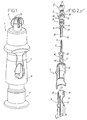
figure 1 en est une vue en perspective ; - la
figure 2 en est une vue en perspective éclatée, en coupe passant par son axe ; - la
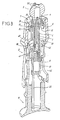
figure 3 en est une vue en perspective et en coupe passant par son axe, à l'état monté ; - la
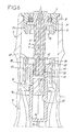
figure 4 est une vue partielle, à échelle agrandie, de son extrémité distale, en coupe selon un plan perpendiculaire au plan de coupe desfigures 2 et3 , dans une position de maintien de moyens de maintien de l'aiguille que comprend ce dispositif ; - la
figure 5 est une vue du dispositif similaire à lafigure 4 , dans une position de relâchement de ces moyens de maintien de l'aiguille ; - les
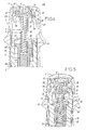
figures 6 à 8 en sont des vues partielles, à échelle agrandie, en coupe passant par son axe, respectivement en position de stockage, en cours d'injection, et en fin d'injection, et - la
figure 9 montre, à échelle agrandie, un capuchon que comprend le dispositif.
- The
figure 1 is a perspective view; - the
figure 2 is an exploded perspective view, in section passing through its axis; - the
figure 3 is a perspective view in section passing through its axis, in the mounted state; - the
figure 4 is a partial view, on an enlarged scale, of its distal end, in section along a plane perpendicular to the cutting plane of thefigures 2 and3 in a holding position of the needle holding means included in this device; - the
figure 5 is a view of the device similar to thefigure 4 in a position of relaxation of these means for holding the needle; - the
Figures 6 to 8 are partial views, on an enlarged scale, in section passing through its axis, respectively in the storage position, during injection, and at the end of injection, and - the
figure 9 shows, on an enlarged scale, a cap that includes the device.
Les figures représentent un dispositif 1 d'injection d'un produit, notamment à usage médical.The figures represent a
Comme le montre plus particulièrement la
Le corps 2 présente une forme générale tubulaire, et comprend une nervure circulaire 15 au niveau de son extrémité distale.The
Le capuchon 3 présente des ailes de préhension 20 et peut être clipé sur un bossage 21 que forme l'une des pièces 6 de montage de l'aiguille 4. Comme le montre la
L'aiguille 4 est fixée à la pièce 5. Celle-ci a une forme générale cylindrique et présente une rainure et un perçage qui forment un conduit d'écoulement communiquant avec la cavité de l'aiguille 4.The
La pièce 6 présente une partie proximale 26 de forme tubulaire qui reçoit étroitement la pièce 5 en elle, et comprend un trou distal pour permettre l'engagement de l'aiguille 4 au travers du bossage 21. La partie 26 est destinée à être introduite dans le récipient 10, comme mentionné plus haut et comporte un joint d'étanchéité 25 à son niveau proximal. Cette partie 26 permet ainsi de déplacer le piston 11 dans le récipient 10 lorsque le poussoir 9 est déplacé par rapport au corps 2, comme cela apparaîtra plus loin.The
La pièce 6 comprend également une collerette 27 propre à être clipée dans des ouvertures 28, plus particulièrement visibles sur la
La pièce 7 est destinée à être insérée étroitement dans l'ouverture délimitée par la nervure distale 15 du corps 2, une collerette distale 30 qu'elle comprend prenant place dans l'évidement distal délimité par cette nervure 15. Cet engagement étroit permet la fixation de la pièce 7 au corps 2.The
La pièce 7 comprend également une ouverture permettant le passage du bossage 21 et la mise en place du capuchon 3 sur ce bossage. Cette ouverture est délimitée par un rebord 31 de diamètre inférieur au diamètre du ressort 8.The
Comme le montre la
La pièce 7 comprend en outre des parois 32 entre les pattes 29. Il apparaît sur les
Le poussoir 9 est engagé dans le corps 2 et peut coulisser par rapport à celui-ci. Il comprend des nervures latérales 35 de guidage latéral du récipient 10.The
À son niveau proximal, le poussoir 9 forme deux pattes 39 mobiles radialement, pourvues de saillies internes 41 formant des butées de réception d'une collerette 45 que comprend le récipient 10. Cette venue en butée de la collerette 45 contre les saillies 41 permet de lier la collerette 45 au poussoir 9 dans le sens de déplacement du poussoir 9 qui permet de réaliser l'injection.At its proximal level, the
Le poussoir 9 forme également deux parois 42 situées entre les pattes 39. Comme le montrent les
Du côté opposé à la collerette 45, le récipient 10 comprend un fond 46. Le produit à injecter est contenu entre le piston 11 et les parois du récipient 10.On the opposite side to the
Le piston 11 est en une matière souple, notamment en élastomère. Il présente une forme conique et est placé dans le récipient 10 de telle sorte que sa face de plus faible surface soit tournée vers le produit à injecter. Il ménage ainsi, comme le montre la
Comme le montre la comparaison des
En pratique, le dispositif 1 se trouve à l'origine dans la position de stockage représentée sur la
Le déplacement du récipient 10 avec le poussoir 9 presse le piston 11 contre le produit à injecter, ce qui amène à l'écoulement du produit entre le piston 11 et le récipient 10, comme cela apparaît sur la
À l'approche de la position de fin de course d'injection, les rampes des pattes 39 et des parois 42 viennent porter contre, respectivement, les rampes des parois 32 et des pattes 29, de telle sorte que les pattes 29 et 39 sont déplacées vers des positions radialement extérieures dans lesquelles elles libères respectivement les collerettes 27 et 45. Le ressort 8 peut alors se relâcher, ce qui provoque un recul simultané des pièces 5 et 6, et donc de l'aiguille 4, ainsi que du récipient 10 du fait du frottement du joint 25, vers une position de rétraction montrée sur la
Il apparaît de ce qui précède que l'invention apporte des améliorations déterminantes aux dispositifs homologues de la technique antérieure, en assurant une parfaite sécurité contre les risques de piqûres accidentelles susceptibles de se produire après l'injection.It is apparent from the foregoing that the invention provides decisive improvements to prior art counterparts, providing complete safety against the risks of accidental punctures that may occur after injection.
Il va de soi que l'invention n'est pas limitée à la forme de réalisation décrite ci-dessus à titre d'exemple mais qu'elle en embrasse au contraire toutes les variantes de réalisation entrant dans le champ de protection défini par les revendications ci-annexées. En particulier, le piston peut comprendre une zone transperçable placée en regard de l'extrémité proximale de l'aiguille, cette extrémité proximale dépassant, du côté proximale de la pièce 5 qui le comporte.It goes without saying that the invention is not limited to the embodiment described above by way of example but that it embraces on the contrary all variants within the scope of protection defined by the claims appended. In particular, the piston may comprise a pierceable area placed facing the proximal end of the needle, this proximal end protruding, on the proximal side of the
Claims (8)
- A device (1) for injecting a product, particularly for medical use, which comprises:- a body (2) housing a hollow injection needle (4) and a container (10) containing the injectable product; the needle (4) is connected to the body (2) but able to move relative to the latter between an injection position and a retracted position;- a plunger (9) that slides in the body (2) and is displaceable relative to the latter to perform the injection; said container (10) being closed at one end;- means (5-7; 28, 29) for keeping the needle (4) in position, which means normally keep the needle (4) in the injection position and can be released to free the needle (4) to move to said retracted position;- a piston (11) engaged in the container (10), said piston (11) being movable in the container (10) when the plunger (9) is moved with respect to the body (2), said piston (1) being so shaped that, in a first configuration of the piston or relative position of this piston (11) and of this container (10), it closes the container (10) in such a way as to isolate the product from the environment outside this container (10),characterized in that said piston (11) is so shaped that, in a second configuration of the piston (11) or relative position of this piston (11) and of this container (10), it allows the product to pass out of the container (10),
the device further comprising- means (45, 39, 41) for keeping the container (10) in position and linking said container (10) to said plunger (9), said container (10) being movable with respect to the plunger (9) between a position that enables the injection to be performed and a retraction position, said means (45, 39, 41) for keeping the container (10) in position normally keeping the container (10) in the position that enables the injection to be performed, and being releasable to free the container (10) to move to said retracted position;- respective means (32, 42) for operating said means (5-7; 28, 29) for keeping the needle (4) in position and said means (45, 39, 41) for keeping the container (10) in position, which, at the end of the injection, release the means for keeping the needle (4) in position before, or at the same time as, the means for keeping the container (10) in position are released. - The injection device (1) as claimed in claim 1, in which the piston (11) is so shaped that, in said second configuration or position, it allows the product to pass between itself and the container.
- The injection device (1) as claimed in claim 2, in which the piston (11) comprises at least one peripheral zone that is able, in said first configuration of the piston (11), to press tightly against the wall of the container (10), and, in said second configuration of the piston (11), to withdraw under the pressure of the injectable product to allow the latter to pass it.
- The injection device (1) as claimed in claim 1, in which the piston comprises a pierceable zone located in line with the proximal end of the needle.
- The injection device (1) as claimed in one of claims 1-4, which comprises spring means (8) for moving the needle (4) and the container (10) to the retracted position without voluntary external action.
- The injection device (1) as claimed in one of claims 1-5, in which said body (2) forms a distal wall (7, 21) perpendicular to the axis of the needle (4), from which the needle (4) projects, in the injection position, to a distance equal to the desired depth of insertion of this needle (4) during the injection.
- The injection device (1) as claimed in one of claims 1-6, in which said means for keeping the needle (4) in position comprise:- a needle-supporting part (6) comprising at least one locking means (27); and- at least one tab (29) that comprises a locking means (28) able to engage with that of said needle-supporting part (6), this tab (29) being moveable radially between a normal, radially inward position, in which said locking means (27, 29) engage with each other to keep said needle-supporting part (6) in position relative to said body (2), and a radially outward position, in which a zone (42) of the plunger (9) moves this tab (29) radially out to unlock it, thereby freeing said needle-supporting part (6) from said body (2).
- The injection device (1) as claimed in one of claims 1-7, in which said means for keeping the container (10) in position comprise:- a flange (45) formed at the opposite end of the container (10) from the closed end of this container (10);- engagement means (41) integral with said plunger (9) for connecting said flange (45) to the plunger (9) ; and- at least one tab (39) comprising said engagement means (41) and able to move in the radial direction of this plunger (9) between a radially inward position, in which said engagement means (41) connect said flange (45) to the plunger (9), and a radially outward position, in which said engagement means (41) are withdrawn radially wide of this flange (45), thereby releasing it.
Applications Claiming Priority (3)
| Application Number | Priority Date | Filing Date | Title |
|---|---|---|---|
| FR0209238A FR2842428B1 (en) | 2002-07-19 | 2002-07-19 | DEVICE FOR INJECTING A PRODUCT, ESPECIALLY FOR MEDICAL USE |
| FR0209238 | 2002-07-19 | ||
| PCT/FR2003/002252 WO2004009164A2 (en) | 2002-07-19 | 2003-07-16 | Device for injecting a product, in particular for medical use |
Publications (2)
| Publication Number | Publication Date |
|---|---|
| EP1523359A2 EP1523359A2 (en) | 2005-04-20 |
| EP1523359B1 true EP1523359B1 (en) | 2013-06-26 |
Family
ID=29797608
Family Applications (1)
| Application Number | Title | Priority Date | Filing Date |
|---|---|---|---|
| EP03748215.5A Expired - Lifetime EP1523359B1 (en) | 2002-07-19 | 2003-07-16 | Device for injecting a product, in particular for medical use |
Country Status (7)
| Country | Link |
|---|---|
| US (1) | US7618401B2 (en) |
| EP (1) | EP1523359B1 (en) |
| JP (1) | JP4717438B2 (en) |
| AU (1) | AU2003267524A1 (en) |
| ES (1) | ES2427540T3 (en) |
| FR (1) | FR2842428B1 (en) |
| WO (1) | WO2004009164A2 (en) |
Families Citing this family (12)
| Publication number | Priority date | Publication date | Assignee | Title |
|---|---|---|---|---|
| FR2860161B1 (en) * | 2003-09-26 | 2006-06-02 | Becton Dickinson France | DEVICE FOR INJECTING A PRODUCT, IN PARTICULAR FOR MEDICAL USE |
| GB0414054D0 (en) | 2004-06-23 | 2004-07-28 | Owen Mumford Ltd | Improvements relating to automatic injection devices |
| KR101396797B1 (en) | 2006-06-30 | 2014-05-26 | 애브비 바이오테크놀로지 리미티드 | Automatic injection device |
| MX2011011541A (en) | 2009-04-29 | 2012-02-28 | Abbott Biotech Ltd | Automatic injection device. |
| BR112012014710A2 (en) | 2009-12-15 | 2017-07-25 | Abbott Biotech Ltd | optimized ignition button for automatic injection device |
| WO2011133823A1 (en) | 2010-04-21 | 2011-10-27 | Abbott Biotechnology Ltd. | Wearable automatic injection device for controlled delivery of therapeutic agents |
| WO2012101629A1 (en) | 2011-01-24 | 2012-08-02 | Elcam Medical Agricultural Cooperative Association Ltd. | Injector |
| EP2667918B1 (en) | 2011-01-24 | 2017-03-01 | AbbVie Biotechnology Ltd | Automatic injection devices having overmolded gripping surfaces |
| KR101702339B1 (en) | 2011-01-24 | 2017-02-03 | 애브비 바이오테크놀로지 리미티드 | Removal of needle shields from syringes and automatic injection devices |
| EP2742963A1 (en) * | 2012-12-17 | 2014-06-18 | Sanofi-Aventis Deutschland GmbH | Drug delivery device |
| USD765838S1 (en) | 2015-03-26 | 2016-09-06 | Tech Group Europe Limited | Syringe retention clip |
| USD818575S1 (en) * | 2015-12-08 | 2018-05-22 | Becton Dickinson France S.A.S. | Medical injector with enhanced grip |
Family Cites Families (10)
| Publication number | Priority date | Publication date | Assignee | Title |
|---|---|---|---|---|
| US4929230A (en) * | 1988-09-30 | 1990-05-29 | Pfleger Frederick W | Syringe construction |
| US5320606A (en) * | 1993-03-17 | 1994-06-14 | Jore Matthew B | Single use hypodermic safety syringe |
| US6123688A (en) * | 1995-08-22 | 2000-09-26 | Mdc Investment Holdings, Inc. | Pre-filled retractable needle injection devices |
| FR2750051A1 (en) * | 1996-06-21 | 1997-12-26 | Debiotech Sa | Medical syringe comprise one or more free pistons of elastic material |
| EP0927054B1 (en) * | 1996-09-03 | 2004-03-10 | MDC Investment Holdings, Inc. | Pre-filled medical injection device having retractable needle |
| US6569115B1 (en) * | 1997-08-28 | 2003-05-27 | Mdc Investment Holdings, Inc. | Pre-filled retractable needle injection device |
| DE19749514A1 (en) * | 1997-11-08 | 1999-05-12 | Pfeiffer Erich Gmbh & Co Kg | Delivery of a mixture of media for e.g. pharmaceutical products |
| PT1066071E (en) * | 1998-03-17 | 2004-03-31 | Mdc Invest Holdings Inc | PREVIOUSLY FULL INJECTION DEVICE PROVIDED WITH A RETRACTABLE NEEDLE |
| US7329238B2 (en) * | 1999-12-07 | 2008-02-12 | Specialized Health Products Inc. | Safety needle medical bearing devices |
| ATE399033T1 (en) * | 2001-03-13 | 2008-07-15 | Mdc Invest Holdings Inc | PREFILLED SAFETY DILUENT INJECTOR |
-
2002
- 2002-07-19 FR FR0209238A patent/FR2842428B1/en not_active Expired - Lifetime
-
2003
- 2003-07-16 WO PCT/FR2003/002252 patent/WO2004009164A2/en active Application Filing
- 2003-07-16 AU AU2003267524A patent/AU2003267524A1/en not_active Abandoned
- 2003-07-16 EP EP03748215.5A patent/EP1523359B1/en not_active Expired - Lifetime
- 2003-07-16 ES ES03748215T patent/ES2427540T3/en not_active Expired - Lifetime
- 2003-07-16 JP JP2004522246A patent/JP4717438B2/en not_active Expired - Lifetime
- 2003-07-16 US US10/520,981 patent/US7618401B2/en not_active Expired - Lifetime
Also Published As
| Publication number | Publication date |
|---|---|
| US7618401B2 (en) | 2009-11-17 |
| FR2842428A1 (en) | 2004-01-23 |
| AU2003267524A1 (en) | 2004-02-09 |
| JP4717438B2 (en) | 2011-07-06 |
| EP1523359A2 (en) | 2005-04-20 |
| JP2005532885A (en) | 2005-11-04 |
| US20060111674A1 (en) | 2006-05-25 |
| WO2004009164A2 (en) | 2004-01-29 |
| WO2004009164A3 (en) | 2004-04-08 |
| AU2003267524A8 (en) | 2004-02-09 |
| ES2427540T3 (en) | 2013-10-30 |
| FR2842428B1 (en) | 2004-10-08 |
Similar Documents
| Publication | Publication Date | Title |
|---|---|---|
| EP1485153B1 (en) | Needle protection device for a syringe and an injection device comprising a syringe and said protection device | |
| EP1079877B1 (en) | Injection syringe with needle shield loaded with a spring | |
| EP1330279B1 (en) | Injection syringe with mobile needle guard | |
| EP1523359B1 (en) | Device for injecting a product, in particular for medical use | |
| EP1224000B1 (en) | Safety device for injection syringe | |
| EP1257308B1 (en) | Device for injecting a dose of liquid, in particular medicinal liquid | |
| EP0336855B1 (en) | Single use syringe | |
| EP2200681B1 (en) | Syringe device comprising a syringe body and a bearing sleeve | |
| EP1682207A2 (en) | Protected injection syringe device | |
| WO2001024856A1 (en) | Disposable injection device | |
| EP0114145A2 (en) | Syringe for medical use | |
| EP1605997A1 (en) | Device for protection of the needle for a syringe and injection device comprising a syringe and said protection device | |
| WO1991013643A1 (en) | Syringe with self-retracting needle | |
| FR2807665A1 (en) | MEDICAL SYRINGE | |
| WO1995027524A1 (en) | Single-use syringe with retractable needle | |
| EP1372772B1 (en) | Syringe with improved safety | |
| EP1673122B1 (en) | Device for injecting a product, primarily for medical use | |
| WO2002070055A1 (en) | Syringe or similar device | |
| FR2871705A1 (en) | DEVICE FOR SINGLE USE INJECTION OF A MEDICINAL FLUID | |
| FR2727021A1 (en) | Single-use syringe with automatic retraction of needle | |
| FR2778852A1 (en) | Syringe with retractable needle | |
| FR2934165A1 (en) | SECURE INJECTION DEVICE FOR SINGLE USE | |
| EP1381414B1 (en) | Syringe | |
| FR2684004A1 (en) | Medical syringe fitted with an articulated and lockable needle protection | |
| EP1368081B1 (en) | Syringe |
Legal Events
| Date | Code | Title | Description |
|---|---|---|---|
| PUAI | Public reference made under article 153(3) epc to a published international application that has entered the european phase |
Free format text: ORIGINAL CODE: 0009012 |
|
| 17P | Request for examination filed |
Effective date: 20050118 |
|
| AK | Designated contracting states |
Kind code of ref document: A2 Designated state(s): AT BE BG CH CY CZ DE DK EE ES FI FR GB GR HU IE IT LI LU MC NL PT RO SE SI SK TR |
|
| AX | Request for extension of the european patent |
Extension state: AL LT LV MK |
|
| RAP1 | Party data changed (applicant data changed or rights of an application transferred) |
Owner name: BECTON DICKINSON FRANCE |
|
| DAX | Request for extension of the european patent (deleted) | ||
| RIN1 | Information on inventor provided before grant (corrected) |
Inventor name: VEDRINE, LIONEL |
|
| 17Q | First examination report despatched |
Effective date: 20100608 |
|
| RIN1 | Information on inventor provided before grant (corrected) |
Inventor name: VEDRINE, LIONEL |
|
| GRAP | Despatch of communication of intention to grant a patent |
Free format text: ORIGINAL CODE: EPIDOSNIGR1 |
|
| RIC1 | Information provided on ipc code assigned before grant |
Ipc: A61M 5/24 20060101ALI20121210BHEP Ipc: A61M 5/32 20060101AFI20121210BHEP |
|
| GRAS | Grant fee paid |
Free format text: ORIGINAL CODE: EPIDOSNIGR3 |
|
| GRAA | (expected) grant |
Free format text: ORIGINAL CODE: 0009210 |
|
| AK | Designated contracting states |
Kind code of ref document: B1 Designated state(s): AT BE BG CH CY CZ DE DK EE ES FI FR GB GR HU IE IT LI LU MC NL PT RO SE SI SK TR |
|
| REG | Reference to a national code |
Ref country code: GB Ref legal event code: FG4D Free format text: NOT ENGLISH |
|
| REG | Reference to a national code |
Ref country code: CH Ref legal event code: EP |
|
| REG | Reference to a national code |
Ref country code: AT Ref legal event code: REF Ref document number: 618411 Country of ref document: AT Kind code of ref document: T Effective date: 20130715 |
|
| REG | Reference to a national code |
Ref country code: IE Ref legal event code: FG4D Free format text: LANGUAGE OF EP DOCUMENT: FRENCH |
|
| REG | Reference to a national code |
Ref country code: DE Ref legal event code: R096 Ref document number: 60344370 Country of ref document: DE Effective date: 20130814 |
|
| REG | Reference to a national code |
Ref country code: ES Ref legal event code: FG2A Ref document number: 2427540 Country of ref document: ES Kind code of ref document: T3 Effective date: 20131030 |
|
| PG25 | Lapsed in a contracting state [announced via postgrant information from national office to epo] |
Ref country code: SE Free format text: LAPSE BECAUSE OF FAILURE TO SUBMIT A TRANSLATION OF THE DESCRIPTION OR TO PAY THE FEE WITHIN THE PRESCRIBED TIME-LIMIT Effective date: 20130626 Ref country code: FI Free format text: LAPSE BECAUSE OF FAILURE TO SUBMIT A TRANSLATION OF THE DESCRIPTION OR TO PAY THE FEE WITHIN THE PRESCRIBED TIME-LIMIT Effective date: 20130626 Ref country code: GR Free format text: LAPSE BECAUSE OF FAILURE TO SUBMIT A TRANSLATION OF THE DESCRIPTION OR TO PAY THE FEE WITHIN THE PRESCRIBED TIME-LIMIT Effective date: 20130927 Ref country code: SI Free format text: LAPSE BECAUSE OF FAILURE TO SUBMIT A TRANSLATION OF THE DESCRIPTION OR TO PAY THE FEE WITHIN THE PRESCRIBED TIME-LIMIT Effective date: 20130626 |
|
| REG | Reference to a national code |
Ref country code: AT Ref legal event code: MK05 Ref document number: 618411 Country of ref document: AT Kind code of ref document: T Effective date: 20130626 |
|
| PG25 | Lapsed in a contracting state [announced via postgrant information from national office to epo] |
Ref country code: BG Free format text: LAPSE BECAUSE OF FAILURE TO SUBMIT A TRANSLATION OF THE DESCRIPTION OR TO PAY THE FEE WITHIN THE PRESCRIBED TIME-LIMIT Effective date: 20130926 |
|
| REG | Reference to a national code |
Ref country code: NL Ref legal event code: VDEP Effective date: 20130626 |
|
| BERE | Be: lapsed |
Owner name: BECTON DICKINSON FRANCE Effective date: 20130731 |
|
| PG25 | Lapsed in a contracting state [announced via postgrant information from national office to epo] |
Ref country code: EE Free format text: LAPSE BECAUSE OF FAILURE TO SUBMIT A TRANSLATION OF THE DESCRIPTION OR TO PAY THE FEE WITHIN THE PRESCRIBED TIME-LIMIT Effective date: 20130626 Ref country code: SK Free format text: LAPSE BECAUSE OF FAILURE TO SUBMIT A TRANSLATION OF THE DESCRIPTION OR TO PAY THE FEE WITHIN THE PRESCRIBED TIME-LIMIT Effective date: 20130626 Ref country code: AT Free format text: LAPSE BECAUSE OF FAILURE TO SUBMIT A TRANSLATION OF THE DESCRIPTION OR TO PAY THE FEE WITHIN THE PRESCRIBED TIME-LIMIT Effective date: 20130626 Ref country code: CY Free format text: LAPSE BECAUSE OF FAILURE TO SUBMIT A TRANSLATION OF THE DESCRIPTION OR TO PAY THE FEE WITHIN THE PRESCRIBED TIME-LIMIT Effective date: 20130703 Ref country code: PT Free format text: LAPSE BECAUSE OF FAILURE TO SUBMIT A TRANSLATION OF THE DESCRIPTION OR TO PAY THE FEE WITHIN THE PRESCRIBED TIME-LIMIT Effective date: 20131028 Ref country code: CZ Free format text: LAPSE BECAUSE OF FAILURE TO SUBMIT A TRANSLATION OF THE DESCRIPTION OR TO PAY THE FEE WITHIN THE PRESCRIBED TIME-LIMIT Effective date: 20130626 |
|
| PG25 | Lapsed in a contracting state [announced via postgrant information from national office to epo] |
Ref country code: RO Free format text: LAPSE BECAUSE OF FAILURE TO SUBMIT A TRANSLATION OF THE DESCRIPTION OR TO PAY THE FEE WITHIN THE PRESCRIBED TIME-LIMIT Effective date: 20130626 Ref country code: NL Free format text: LAPSE BECAUSE OF FAILURE TO SUBMIT A TRANSLATION OF THE DESCRIPTION OR TO PAY THE FEE WITHIN THE PRESCRIBED TIME-LIMIT Effective date: 20130626 |
|
| REG | Reference to a national code |
Ref country code: CH Ref legal event code: PL |
|
| PG25 | Lapsed in a contracting state [announced via postgrant information from national office to epo] |
Ref country code: CY Free format text: LAPSE BECAUSE OF FAILURE TO SUBMIT A TRANSLATION OF THE DESCRIPTION OR TO PAY THE FEE WITHIN THE PRESCRIBED TIME-LIMIT Effective date: 20130626 Ref country code: MC Free format text: LAPSE BECAUSE OF FAILURE TO SUBMIT A TRANSLATION OF THE DESCRIPTION OR TO PAY THE FEE WITHIN THE PRESCRIBED TIME-LIMIT Effective date: 20130626 |
|
| REG | Reference to a national code |
Ref country code: IE Ref legal event code: MM4A |
|
| PG25 | Lapsed in a contracting state [announced via postgrant information from national office to epo] |
Ref country code: BE Free format text: LAPSE BECAUSE OF NON-PAYMENT OF DUE FEES Effective date: 20130731 Ref country code: DK Free format text: LAPSE BECAUSE OF FAILURE TO SUBMIT A TRANSLATION OF THE DESCRIPTION OR TO PAY THE FEE WITHIN THE PRESCRIBED TIME-LIMIT Effective date: 20130626 Ref country code: CH Free format text: LAPSE BECAUSE OF NON-PAYMENT OF DUE FEES Effective date: 20130731 Ref country code: LI Free format text: LAPSE BECAUSE OF NON-PAYMENT OF DUE FEES Effective date: 20130731 |
|
| PLBE | No opposition filed within time limit |
Free format text: ORIGINAL CODE: 0009261 |
|
| STAA | Information on the status of an ep patent application or granted ep patent |
Free format text: STATUS: NO OPPOSITION FILED WITHIN TIME LIMIT |
|
| 26N | No opposition filed |
Effective date: 20140327 |
|
| REG | Reference to a national code |
Ref country code: DE Ref legal event code: R097 Ref document number: 60344370 Country of ref document: DE Effective date: 20140327 |
|
| PG25 | Lapsed in a contracting state [announced via postgrant information from national office to epo] |
Ref country code: IE Free format text: LAPSE BECAUSE OF NON-PAYMENT OF DUE FEES Effective date: 20130716 |
|
| PG25 | Lapsed in a contracting state [announced via postgrant information from national office to epo] |
Ref country code: TR Free format text: LAPSE BECAUSE OF FAILURE TO SUBMIT A TRANSLATION OF THE DESCRIPTION OR TO PAY THE FEE WITHIN THE PRESCRIBED TIME-LIMIT Effective date: 20130626 |
|
| PG25 | Lapsed in a contracting state [announced via postgrant information from national office to epo] |
Ref country code: LU Free format text: LAPSE BECAUSE OF NON-PAYMENT OF DUE FEES Effective date: 20130716 Ref country code: HU Free format text: LAPSE BECAUSE OF FAILURE TO SUBMIT A TRANSLATION OF THE DESCRIPTION OR TO PAY THE FEE WITHIN THE PRESCRIBED TIME-LIMIT; INVALID AB INITIO Effective date: 20030716 |
|
| REG | Reference to a national code |
Ref country code: FR Ref legal event code: PLFP Year of fee payment: 14 |
|
| REG | Reference to a national code |
Ref country code: FR Ref legal event code: PLFP Year of fee payment: 15 |
|
| REG | Reference to a national code |
Ref country code: FR Ref legal event code: PLFP Year of fee payment: 16 |
|
| PGFP | Annual fee paid to national office [announced via postgrant information from national office to epo] |
Ref country code: IT Payment date: 20220621 Year of fee payment: 20 Ref country code: GB Payment date: 20220621 Year of fee payment: 20 |
|
| PGFP | Annual fee paid to national office [announced via postgrant information from national office to epo] |
Ref country code: FR Payment date: 20220622 Year of fee payment: 20 |
|
| PGFP | Annual fee paid to national office [announced via postgrant information from national office to epo] |
Ref country code: ES Payment date: 20220801 Year of fee payment: 20 Ref country code: DE Payment date: 20220621 Year of fee payment: 20 |
|
| REG | Reference to a national code |
Ref country code: DE Ref legal event code: R071 Ref document number: 60344370 Country of ref document: DE |
|
| REG | Reference to a national code |
Ref country code: ES Ref legal event code: FD2A Effective date: 20230726 |
|
| REG | Reference to a national code |
Ref country code: GB Ref legal event code: PE20 Expiry date: 20230715 |
|
| PG25 | Lapsed in a contracting state [announced via postgrant information from national office to epo] |
Ref country code: GB Free format text: LAPSE BECAUSE OF EXPIRATION OF PROTECTION Effective date: 20230715 Ref country code: ES Free format text: LAPSE BECAUSE OF EXPIRATION OF PROTECTION Effective date: 20230717 |