EP1523359B1 - Injektions- oder zerstäubungsvorrichtung, insbesondere zum medizinischen gebrauch - Google Patents
Injektions- oder zerstäubungsvorrichtung, insbesondere zum medizinischen gebrauch Download PDFInfo
- Publication number
- EP1523359B1 EP1523359B1 EP03748215.5A EP03748215A EP1523359B1 EP 1523359 B1 EP1523359 B1 EP 1523359B1 EP 03748215 A EP03748215 A EP 03748215A EP 1523359 B1 EP1523359 B1 EP 1523359B1
- Authority
- EP
- European Patent Office
- Prior art keywords
- container
- needle
- piston
- injection
- keeping
- Prior art date
- Legal status (The legal status is an assumption and is not a legal conclusion. Google has not performed a legal analysis and makes no representation as to the accuracy of the status listed.)
- Expired - Lifetime
Links
Images


Classifications
-
- A—HUMAN NECESSITIES
- A61—MEDICAL OR VETERINARY SCIENCE; HYGIENE
- A61M—DEVICES FOR INTRODUCING MEDIA INTO, OR ONTO, THE BODY; DEVICES FOR TRANSDUCING BODY MEDIA OR FOR TAKING MEDIA FROM THE BODY; DEVICES FOR PRODUCING OR ENDING SLEEP OR STUPOR
- A61M5/00—Devices for bringing media into the body in a subcutaneous, intra-vascular or intramuscular way; Accessories therefor, e.g. filling or cleaning devices, arm-rests
- A61M5/178—Syringes
- A61M5/31—Details
- A61M5/32—Needles; Details of needles pertaining to their connection with syringe or hub; Accessories for bringing the needle into, or holding the needle on, the body; Devices for protection of needles
- A61M5/3205—Apparatus for removing or disposing of used needles or syringes, e.g. containers; Means for protection against accidental injuries from used needles
- A61M5/321—Means for protection against accidental injuries by used needles
- A61M5/322—Retractable needles, i.e. disconnected from and withdrawn into the syringe barrel by the piston
- A61M5/3232—Semi-automatic needle retraction, i.e. in which triggering of the needle retraction requires a deliberate action by the user, e.g. manual release of spring-biased retraction means
-
- A—HUMAN NECESSITIES
- A61—MEDICAL OR VETERINARY SCIENCE; HYGIENE
- A61M—DEVICES FOR INTRODUCING MEDIA INTO, OR ONTO, THE BODY; DEVICES FOR TRANSDUCING BODY MEDIA OR FOR TAKING MEDIA FROM THE BODY; DEVICES FOR PRODUCING OR ENDING SLEEP OR STUPOR
- A61M5/00—Devices for bringing media into the body in a subcutaneous, intra-vascular or intramuscular way; Accessories therefor, e.g. filling or cleaning devices, arm-rests
- A61M5/178—Syringes
- A61M5/24—Ampoule syringes, i.e. syringes with needle for use in combination with replaceable ampoules or carpules, e.g. automatic
- A61M5/2422—Ampoule syringes, i.e. syringes with needle for use in combination with replaceable ampoules or carpules, e.g. automatic using emptying means to expel or eject media, e.g. pistons, deformation of the ampoule, or telescoping of the ampoule
- A61M5/2429—Ampoule syringes, i.e. syringes with needle for use in combination with replaceable ampoules or carpules, e.g. automatic using emptying means to expel or eject media, e.g. pistons, deformation of the ampoule, or telescoping of the ampoule by telescoping of ampoules or carpules with the syringe body
-
- A—HUMAN NECESSITIES
- A61—MEDICAL OR VETERINARY SCIENCE; HYGIENE
- A61M—DEVICES FOR INTRODUCING MEDIA INTO, OR ONTO, THE BODY; DEVICES FOR TRANSDUCING BODY MEDIA OR FOR TAKING MEDIA FROM THE BODY; DEVICES FOR PRODUCING OR ENDING SLEEP OR STUPOR
- A61M5/00—Devices for bringing media into the body in a subcutaneous, intra-vascular or intramuscular way; Accessories therefor, e.g. filling or cleaning devices, arm-rests
- A61M5/178—Syringes
- A61M5/24—Ampoule syringes, i.e. syringes with needle for use in combination with replaceable ampoules or carpules, e.g. automatic
- A61M5/2455—Ampoule syringes, i.e. syringes with needle for use in combination with replaceable ampoules or carpules, e.g. automatic with sealing means to be broken or opened
- A61M5/2459—Ampoule syringes, i.e. syringes with needle for use in combination with replaceable ampoules or carpules, e.g. automatic with sealing means to be broken or opened upon internal pressure increase, e.g. pierced or burst
-
- A—HUMAN NECESSITIES
- A61—MEDICAL OR VETERINARY SCIENCE; HYGIENE
- A61M—DEVICES FOR INTRODUCING MEDIA INTO, OR ONTO, THE BODY; DEVICES FOR TRANSDUCING BODY MEDIA OR FOR TAKING MEDIA FROM THE BODY; DEVICES FOR PRODUCING OR ENDING SLEEP OR STUPOR
- A61M5/00—Devices for bringing media into the body in a subcutaneous, intra-vascular or intramuscular way; Accessories therefor, e.g. filling or cleaning devices, arm-rests
- A61M5/178—Syringes
- A61M5/31—Details
- A61M5/315—Pistons; Piston-rods; Guiding, blocking or restricting the movement of the rod or piston; Appliances on the rod for facilitating dosing ; Dosing mechanisms
- A61M5/31511—Piston or piston-rod constructions, e.g. connection of piston with piston-rod
Definitions
- the present invention relates to a device for injecting a product, in particular for medical use.
- This device is intended in particular to allow an intra-dermal injection.
- proximal and distal are considered in relation to the direction of injection of the product.
- WO 01/45776 describes a syringe whose needle can be retracted inside the body of the syringe after the injection.
- the invention aims to remedy this fundamental drawback.
- the object of the invention is therefore to provide a device ensuring perfect injection reliability and perfect safety against the risk of accidental punctures.
- the needle When performing the injection, the needle is held relative to the body in the injection position and the container is held relative to the pusher in the injection position.
- said actuating means respectively cause the relaxation of said needle holding means and said container holding means, which makes it possible to bring the needle and the receptacle in the retracted position. This retraction ensures perfect safety against the risk of accidental punctures.
- the piston may be shaped for, in said second conformation or position, allow the passage of the product between him and the container.
- the piston may in particular comprise at least one peripheral zone, clean, in said first conformation of the piston, to press tightly against the wall of the container, and in said second conformation of the piston, to fade under the pressure of the product to be injected. allow the passage of the latter.
- the piston may also include a pierceable area positioned opposite the proximal end of the needle. Moving the container relative to the needle then causes the proximal end of the needle to pierce this pierced area of the plunger until it comes into communication with the product to be injected and allow the flow of this product through the needle.
- the device comprises spring means for bringing the needle and the container into retraction position without external voluntary intervention.
- said body forms a distal wall perpendicular to the axis of the needle, from which the needle protrudes, in position injection, over a length corresponding to the desired depth of penetration of this needle during injection.
- This distal wall forms a stop wall, intended to bear against the skin during insertion of the needle to limit this depression to said desired depth.
- the device according to the invention is thus particularly suitable for performing intra-dermal injections.
- the needle In the retracted position, the needle can simply be retracted below this wall, proximally, to eliminate the risk of accidental puncture after injection.
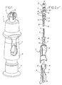
- the figures represent a device 1 for injecting a product, in particular for medical use.
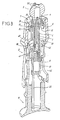
- the device 1 comprises a body 2, a distal protection cap 3, a hollow injection needle 4, parts 5 to 7 for mounting the needle 4, a spring 8, a pusher 9, a container 10 and a piston 11, described in detail below.
- the body 2 has a generally tubular shape, and comprises a circular rib 15 at its distal end.
- the cap 3 has gripping wings 20 and can be clipped onto a boss 21 that forms one of the parts 6 for mounting the needle 4. As shown in FIG. figure 9 , this cap 3 may have at least one opening to allow the escape of air during the insertion of a portion 26 of the part 6 in the container 10, as will appear below. In the embodiment shown in this figure 9 , the cap 3 has a plurality of interrupted ribs 3a, staggered in the axial direction, whose interruptions are angularly offset to form a labyrinth.
- the needle 4 is attached to the part 5.
- This has a generally cylindrical shape and has a groove and a bore which form a flow conduit communicating with the cavity of the needle 4.
- the piece 6 has a tubular-shaped proximal portion 26 which tightly receives the piece 5 in it, and comprises a distal hole to allow the needle 4 to be engaged through the boss 21.
- the part 26 is intended to be inserted into the container 10, as mentioned above, and has a seal 25 at its proximal level. This portion 26 thus moves the piston 11 in the container 10 when the pusher 9 is moved relative to the body 2, as will appear below.
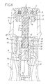
- the part 6 also comprises a flange 27 adapted to be clipped into openings 28, more particularly visible on the figure 4 , that have two lugs 29 secured to the part 7, radially movable relative thereto.
- the part 7 is intended to be inserted tightly into the opening delimited by the distal rib 15 of the body 2, a distal collar 30 which it comprises taking place in the distal recess delimited by this rib 15. This narrow engagement allows the fixation from room 7 to the body 2.
- the part 7 also comprises an opening allowing the passage of the boss 21 and the introduction of the cap 3 on this boss. This opening is delimited by a flange 31 of smaller diameter than the diameter of the spring 8.
- this flange 31 allows the spring 8 to be held in the compressed state between the proximal face of this flange 31 and the distal face of the flange 27 when the part 6 is clipped to the part 7.
- the part 7 further comprises walls 32 between the legs 29. It appears on the figures 3 and 4 that the legs 29 have internal inclined ramps arranged in their proximal parts while the walls 32 have external inclined ramps arranged in their proximal portions.
- the pusher 9 is engaged in the body 2 and can slide relative thereto. It comprises lateral ribs 35 for lateral guidance of the container 10.
- the pusher 9 forms two radially movable tabs 39, provided with internal projections 41 forming abutments for receiving a flange 45 that the container 10 comprises. This abutment of the flange 45 against the projections 41 makes it possible to connect the flange 45 to the pusher 9 in the direction of movement of the pusher 9 which allows the injection.
- the pusher 9 also forms two walls 42 located between the legs 39.
- the tabs 39 comprise, at their distal ends, internal inclined ramps adapted to cooperate with the ramps of the walls 32 at the end of the injection stroke
- the walls 42 comprise, at their distal ends, ramps external inclined clean to cooperate with the internal ramps of the legs 29 also at the end of injection stroke.
- the container 10 On the opposite side to the flange 45, the container 10 comprises a bottom 46.
- the product to be injected is contained between the piston 11 and the walls of the container 10.
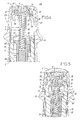
- the piston 11 is made of a flexible material, in particular an elastomer. It has a conical shape and is placed in the container 10 so that its face of smaller surface is turned towards the product to be injected. It thus provides, as shown by the figure 6 , a gap 50 between it and the wall of the container 10.
- the piston 11 comprises a lateral blind hole 51 arranged over a major part of its thickness, from its distal axial face, on the side of the side wall of the piston. 11 which makes it possible to define said gap 50.
- the hole 51 has a shape such that it follows, at least approximately, this lateral wall, and thus delimits a peripheral zone extending over a portion of the periphery of the piston 11.
- this peripheral zone normally adopts a radially external position shown on the figure 6 in which it bears tightly against the wall of the container 10, and can assume a radially internal position shown on the figure 7 in which it disappears under the pressure of the product to be injected during the passage of the latter between the piston 11 and the container 10, resulting from the support of the piston 11 against the product.
- the device 1 is originally in the storage position represented on the figure 6 in which the collar 27 is engaged with the tabs 29 and the collar 45 is held by the projections 41. In this position, the needle 4 protrudes beyond the distal end of the device according to the desired depth for the injection, which is an intradermal injection in the example shown.
- the displacement of the container 10 with the pusher 9 presses the piston 11 against the product to be injected, which leads to the flow of the product between the piston 11 and the container 10, as it appears on the figure 7 .
- the injection is then performed by continuing the movement of the pusher 9 relative to the body 2.
- the ramps of the tabs 39 and walls 42 come to bear against, respectively, the ramps of the walls 32 and tabs 29, so that the tabs 29 and 39 are displaced to radially outer positions in which they respectively release the flanges 27 and 45.
- the spring 8 can then relax, which causes a simultaneous retreat of the parts 5 and 6, and therefore the needle 4, and the container 10 because of the friction of the seal 25, to a retracted position shown on the figure 8 .
- the distal end of the needle 4 is located below the distal face of the part 7 and the collar 45 is located on the proximal side of the projections 41.
- the piston may comprise a pierceable area placed facing the proximal end of the needle, this proximal end protruding, on the proximal side of the part 5 which comprises it.
Landscapes
- Health & Medical Sciences (AREA)
- Engineering & Computer Science (AREA)
- Heart & Thoracic Surgery (AREA)
- Vascular Medicine (AREA)
- Anesthesiology (AREA)
- Biomedical Technology (AREA)
- Hematology (AREA)
- Life Sciences & Earth Sciences (AREA)
- Animal Behavior & Ethology (AREA)
- General Health & Medical Sciences (AREA)
- Public Health (AREA)
- Veterinary Medicine (AREA)
- Environmental & Geological Engineering (AREA)
- Infusion, Injection, And Reservoir Apparatuses (AREA)
Claims (8)
- Injektionsvorrichtung (1) eines Produkts, insbesondere zum medizinischen Gebrauch, die umfasst:- einen Körper (2), der eine hohle Injektionsnadel (4) aufnimmt und einen Behälter (10), der das zu injizierende Produkt enthält; wobei die Nadel (4) mit dem Körper (2) zwischen einer Injektionsstellung und einer eingezogenen Stellung im Verhältnis zu diesem bewegbar verbunden ist,- einen Drücker (9), der gleitend auf dem Körper (2) montiert und im Verhältnis zu diesem verlagerbar ist, um die Injektion durchzuführen, wobei der Behälter (10) an einem Ende geschlossen ist,- Haltemittel (5 bis 7; 28, 29) der Nadel (4), die die Nadel (4) normal in Injektionsstellung halten, die losgelassen werden können, um die Verlagerung der Nadel (4) in die eingezogene Stellung freizugeben,- einen Kolben (11), der in den Behälter (10) eingeführt ist, wobei der Kolben (11) in dem Behälter (10) verlagerbar ist, wenn der Drücker (9) im Verhältnis zum Körper (2) verlagert wird, wobei der Kolben (11) ausgebildet ist, um in einer ersten Ausbildung des Kolbens (11) oder relativen Stellung dieses Kolbens (11) und dieses Behälters (10) den Behälter (10) derart zu verschließen, dass das Produkt im Verhältnis zur Außenwelt dieses Behälters (10) isoliert ist,dadurch gekennzeichnet, dass der Kolben (11) ausgebildet ist, um in einer zweiten Ausbildung des Kolbens (11) oder relativen Stellung dieses Kolbens (11) und dieses Behälters (10) den Durchgang des Produkts nach außerhalb des Behälters (10) zu erlauben,
wobei die Injektionsvorrichtung (1) ferner umfasst:- Haltemittel (45, 39, 41) des Behälters (10), die den Behälter (10) mit dem Drücker (9) verbinden, wobei der Behälter (10) im Verhältnis zum Drücker (9) zwischen einer Stellung, die die Injektion erlaubt, und einer eingezogenen Stellung bewegbar ist, wobei die Haltemittel (45, 39, 41) des Behälters (10) den Behälter (10) normal in einer Stellung halten, die die Injektion erlaubt, und losgelassen werden können, um die Verlagerung des Behälters (10) in die eingezogene Stellung freizugeben,- jeweilige Betätigungsmittel (32, 42) der Haltemittel (5 bis 7; 28, 29) der Nadel (4) und der Haltemittel (45, 39, 41) des Behälters (10), wobei die jeweiligen Betätigungsmittel imstande sind, am Ende der Injektion die Haltemittel der Nadel (4) vor dem Loslassen der Haltemittel des Behälters (10) loszulassen oder gleichzeitig mit diesem loszulassen. - Injektionsvorrichtung (1) nach Anspruch 1, dadurch gekennzeichnet, dass der Kolben (11) ausgebildet ist, um in der zweiten Ausbildung oder Stellung den Durchgang des Produkts zwischen ihm und dem Behälter (10) zu erlauben.
- Injektionsvorrichtung (1) nach Anspruch 2, dadurch gekennzeichnet, dass der Kolben (11) in der ersten Ausbildung des Kolbens (11) mindestens eine periphere Zone umfasst, die imstande ist, eng gegen die Wand des Behälters (10) zu drücken und sich in der zweiten Ausbildung des Kolbens (11) unter dem Druck des zu injizierenden Produkts zu entfernen, um den Durchgang desselben zu erlauben.
- Injektionsvorrichtung (1) nach Anspruch 1, dadurch gekennzeichnet, dass der Kolben eine durchstoßbare Zone umfasst, die gegenüber dem proximalen Ende der Nadel angeordnet ist.
- Injektionsvorrichtung (1) nach einem der Ansprüche 1 bis 4, dadurch gekennzeichnet, dass sie Federmittel (8) umfasst, die es erlauben, die Nadel (4) und den Behälter (10) ohne gezielten Eingriff von außen in die eingezogene Stellung zu führen.
- Injektionsvorrichtung (1) nach einem der Ansprüche 1 bis 5, dadurch gekennzeichnet, dass der Körper (2) eine distale Wand (7, 21) im rechten Winkel zur Achse der Nadel (4) bildet, ab der die Nadel (4) bei der Injektion in Injektionsstellung über eine entsprechende Länge in der beabsichtigten Eindringtiefe dieser Nadel (4) übersteht.
- Injektionsvorrichtung (1) nach einem der Ansprüche 1 bis 6, dadurch gekennzeichnet, dass die Haltemittel der Nadel (4) umfassen:- ein Teil (6), das die Nadel (4) trägt, welches mindestens ein Verriegelungsmittel (27) aufweist,- mindestens einen Fuß (29), der ein Verriegelungsmittel (28) aufweist, das imstande ist, mit dem des Teils (6), das die Nadel (4) trägt, zusammenzuarbeiten, wobei dieser Fuß (29) zwischen einer radial internen normalen Stellung, in der die Verriegelungsmittel (27, 29) derart in Eingriff kommen, dass das Teil (6), das die Nadel (4) trägt, im Verhältnis zum Körper (2) gehalten wird, und einer radial externen Stellung, in der eine Zone (42) des Drückers (9) diesen Fuß (29) radial nach außen derart verlagert, dass die Verriegelung freigegeben wird, radial bewegbar ist, wodurch folglich das Teil (6), das die Nadel (4) trägt, im Verhältnis zum Körper (2) freigegeben wird.
- Injektionsvorrichtung (1) nach einem der Ansprüche 1 bis 7, dadurch gekennzeichnet, dass die Haltemittel des Behälters (10) umfassen:- einen Kragen (45), der auf Ebene des Endes des Behälters (10) ausgebildet ist, das dem geschlossenen Ende dieses Behälters (10) gegenüberliegt,- Erfassungsmittel (41), die mit dem Drücker (9) verbunden sind, die es erlauben, den Kragen (45) mit dem Drücker (9) zu verbinden, und- mindestens einen Fuß (39), der die Erfassungsmittel (41) aufweist, der in die radiale Richtung dieses Drücker (9) zwischen einer radial internen Stellung, in der die Erfassungsmittel (41) den Kragen (45) mit dem Drücker (9) verbinden, und einer radial externen Stellung, in der die Eingriffmittel (41) radial jenseits dieses Kragens (45) beabstandet sind, den sie folglich freigeben, bewegbar ist.
Applications Claiming Priority (3)
| Application Number | Priority Date | Filing Date | Title |
|---|---|---|---|
| FR0209238 | 2002-07-19 | ||
| FR0209238A FR2842428B1 (fr) | 2002-07-19 | 2002-07-19 | Dispositif d'injection d'un produit, notamment a usage medical |
| PCT/FR2003/002252 WO2004009164A2 (fr) | 2002-07-19 | 2003-07-16 | Dispositif d’injection d’un produit, notamment a usage medical |
Publications (2)
| Publication Number | Publication Date |
|---|---|
| EP1523359A2 EP1523359A2 (de) | 2005-04-20 |
| EP1523359B1 true EP1523359B1 (de) | 2013-06-26 |
Family
ID=29797608
Family Applications (1)
| Application Number | Title | Priority Date | Filing Date |
|---|---|---|---|
| EP03748215.5A Expired - Lifetime EP1523359B1 (de) | 2002-07-19 | 2003-07-16 | Injektions- oder zerstäubungsvorrichtung, insbesondere zum medizinischen gebrauch |
Country Status (7)
| Country | Link |
|---|---|
| US (1) | US7618401B2 (de) |
| EP (1) | EP1523359B1 (de) |
| JP (1) | JP4717438B2 (de) |
| AU (1) | AU2003267524A1 (de) |
| ES (1) | ES2427540T3 (de) |
| FR (1) | FR2842428B1 (de) |
| WO (1) | WO2004009164A2 (de) |
Families Citing this family (13)
| Publication number | Priority date | Publication date | Assignee | Title |
|---|---|---|---|---|
| FR2860161B1 (fr) | 2003-09-26 | 2006-06-02 | Becton Dickinson France | Dispositif d'injection d'un produit, notamment a usage medical |
| GB0414054D0 (en) | 2004-06-23 | 2004-07-28 | Owen Mumford Ltd | Improvements relating to automatic injection devices |
| SG173339A1 (en) | 2006-06-30 | 2011-08-29 | Abbott Biotech Ltd | Automatic injection device |
| US8636704B2 (en) | 2009-04-29 | 2014-01-28 | Abbvie Biotechnology Ltd | Automatic injection device |
| BR112012014710A2 (pt) | 2009-12-15 | 2017-07-25 | Abbott Biotech Ltd | botão de ignição aperfeiçoado para dispositivo de injeção automática |
| KR102071212B1 (ko) | 2010-04-21 | 2020-01-30 | 애브비 바이오테크놀로지 리미티드 | 치료제의 제어된 전달을 위한 착용형 자동 주사 디바이스 |
| CN106075664B (zh) | 2011-01-24 | 2019-07-02 | 艾伯维生物技术有限公司 | 具有模制抓握面的自动注射装置 |
| ES2710905T3 (es) | 2011-01-24 | 2019-04-29 | E3D Agricultural Coop Association Ltd | Inyector |
| EP3473283B1 (de) | 2011-01-24 | 2020-12-09 | AbbVie Biotechnology Ltd. | Entfernung eines nadelschutzes von spritzen und automatische injektionsvorrichtungen |
| USD690418S1 (en) * | 2011-05-02 | 2013-09-24 | Carmel Pharma Ab | Medical device |
| EP2742963A1 (de) * | 2012-12-17 | 2014-06-18 | Sanofi-Aventis Deutschland GmbH | Arzneimittelabgabevorrichtung |
| USD765838S1 (en) | 2015-03-26 | 2016-09-06 | Tech Group Europe Limited | Syringe retention clip |
| USD818575S1 (en) * | 2015-12-08 | 2018-05-22 | Becton Dickinson France S.A.S. | Medical injector with enhanced grip |
Family Cites Families (10)
| Publication number | Priority date | Publication date | Assignee | Title |
|---|---|---|---|---|
| US4929230A (en) * | 1988-09-30 | 1990-05-29 | Pfleger Frederick W | Syringe construction |
| US5320606A (en) * | 1993-03-17 | 1994-06-14 | Jore Matthew B | Single use hypodermic safety syringe |
| US6123688A (en) * | 1995-08-22 | 2000-09-26 | Mdc Investment Holdings, Inc. | Pre-filled retractable needle injection devices |
| FR2750051A1 (fr) * | 1996-06-21 | 1997-12-26 | Debiotech Sa | Seringue medicale a piston libre |
| CA2264532C (en) * | 1996-09-03 | 2004-04-20 | Mdc Investment Holdings, Inc. | Pre-filled retractable needle injection devices |
| US6569115B1 (en) * | 1997-08-28 | 2003-05-27 | Mdc Investment Holdings, Inc. | Pre-filled retractable needle injection device |
| DE19749514A1 (de) * | 1997-11-08 | 1999-05-12 | Pfeiffer Erich Gmbh & Co Kg | Verfahren zum Ausbringen von wenigstens zwei verschiedenen Medien und Spender dafür |
| PL345900A1 (en) * | 1998-03-17 | 2002-01-14 | Mdc Invest Holdings | Pre-filled retractable needle injection device |
| WO2001045776A1 (en) * | 1999-12-07 | 2001-06-28 | Mdc Investment Holdings, Inc. | Safety needle medical bearing devices |
| DE60227245D1 (de) * | 2001-03-13 | 2008-08-07 | Mdc Invest Holdings Inc | Vorgefüllter sicherheits-diluentinjektor |
-
2002
- 2002-07-19 FR FR0209238A patent/FR2842428B1/fr not_active Expired - Lifetime
-
2003
- 2003-07-16 EP EP03748215.5A patent/EP1523359B1/de not_active Expired - Lifetime
- 2003-07-16 WO PCT/FR2003/002252 patent/WO2004009164A2/fr not_active Ceased
- 2003-07-16 ES ES03748215T patent/ES2427540T3/es not_active Expired - Lifetime
- 2003-07-16 JP JP2004522246A patent/JP4717438B2/ja not_active Expired - Lifetime
- 2003-07-16 US US10/520,981 patent/US7618401B2/en not_active Expired - Lifetime
- 2003-07-16 AU AU2003267524A patent/AU2003267524A1/en not_active Abandoned
Also Published As
| Publication number | Publication date |
|---|---|
| FR2842428A1 (fr) | 2004-01-23 |
| AU2003267524A1 (en) | 2004-02-09 |
| EP1523359A2 (de) | 2005-04-20 |
| WO2004009164A3 (fr) | 2004-04-08 |
| FR2842428B1 (fr) | 2004-10-08 |
| US7618401B2 (en) | 2009-11-17 |
| ES2427540T3 (es) | 2013-10-30 |
| WO2004009164A2 (fr) | 2004-01-29 |
| JP2005532885A (ja) | 2005-11-04 |
| AU2003267524A8 (en) | 2004-02-09 |
| US20060111674A1 (en) | 2006-05-25 |
| JP4717438B2 (ja) | 2011-07-06 |
Similar Documents
| Publication | Publication Date | Title |
|---|---|---|
| EP1330279B1 (de) | Injektionsspritze mit einem verschiebbaren nadelschutz | |
| EP1523359B1 (de) | Injektions- oder zerstäubungsvorrichtung, insbesondere zum medizinischen gebrauch | |
| EP1485153B1 (de) | Nadelschutzvorrichtung für eine spritze sowie injektionsvorrichtung bestehend aus einer spritze und dieser schutzvorrichtung | |
| EP1436026B1 (de) | Sicherheitsvorrichtung für eine spritze | |
| EP1224000B1 (de) | Sicherheitsvorrichtung für injektionsspritzen | |
| EP1257308B1 (de) | Injektionsvorrichtung zur verabreichung von insbesondere medizinischen flüssigkeiten | |
| EP0336855B1 (de) | Spritze zum einmaligen Gebrauch | |
| EP2200681B1 (de) | Spritzenvorrichtung mit einem spritzenkörper und einer lagerungshülse | |
| EP1079877A1 (de) | Injektionsspritze mit einem federbeaufschlagten nadelschutz | |
| WO2005039678A2 (fr) | Dispositif de seringue d'injection securise | |
| EP1218047A1 (de) | Injektionsvorrichtung für einmalverwendung | |
| EP0114145A2 (de) | Spritze zum medizinischen Gebrauch | |
| EP1605997A1 (de) | Vorrichtung zum schutz der nadel für eine spritze und eine spritze und diese schutzvorrichtung enthaltende injektionsvorrichtung | |
| EP1326661A1 (de) | Spritze zur selbstinjektion für unmittelbare vermischung von medikamenten | |
| FR2807665A1 (fr) | Seringue medicale | |
| WO1995027524A1 (fr) | Seringue a usage unique a aiguille retractable | |
| EP1372772B1 (de) | Sicherheitsspritze | |
| EP1673122B1 (de) | Vorrichtung zur injektion eines produkts, primär für die medizinische anwendung | |
| WO2002070055A1 (fr) | Seringue, ou dispositif similaire | |
| FR2871705A1 (fr) | Dispositif a usage unique d'injection d'un fluide medicamenteux | |
| FR2934165A1 (fr) | Dispositif securise d'injection a usage unique | |
| FR2778852A1 (fr) | Seringue d'injection a aiguille retractable | |
| EP1381414B1 (de) | Spritze | |
| FR2684004A1 (fr) | Seringue medicale munie d'une protection d'aiguille articulee et verrouillable. | |
| EP1368081B1 (de) | Spritze |
Legal Events
| Date | Code | Title | Description |
|---|---|---|---|
| PUAI | Public reference made under article 153(3) epc to a published international application that has entered the european phase |
Free format text: ORIGINAL CODE: 0009012 |
|
| 17P | Request for examination filed |
Effective date: 20050118 |
|
| AK | Designated contracting states |
Kind code of ref document: A2 Designated state(s): AT BE BG CH CY CZ DE DK EE ES FI FR GB GR HU IE IT LI LU MC NL PT RO SE SI SK TR |
|
| AX | Request for extension of the european patent |
Extension state: AL LT LV MK |
|
| RAP1 | Party data changed (applicant data changed or rights of an application transferred) |
Owner name: BECTON DICKINSON FRANCE |
|
| DAX | Request for extension of the european patent (deleted) | ||
| RIN1 | Information on inventor provided before grant (corrected) |
Inventor name: VEDRINE, LIONEL |
|
| 17Q | First examination report despatched |
Effective date: 20100608 |
|
| RIN1 | Information on inventor provided before grant (corrected) |
Inventor name: VEDRINE, LIONEL |
|
| GRAP | Despatch of communication of intention to grant a patent |
Free format text: ORIGINAL CODE: EPIDOSNIGR1 |
|
| RIC1 | Information provided on ipc code assigned before grant |
Ipc: A61M 5/24 20060101ALI20121210BHEP Ipc: A61M 5/32 20060101AFI20121210BHEP |
|
| GRAS | Grant fee paid |
Free format text: ORIGINAL CODE: EPIDOSNIGR3 |
|
| GRAA | (expected) grant |
Free format text: ORIGINAL CODE: 0009210 |
|
| AK | Designated contracting states |
Kind code of ref document: B1 Designated state(s): AT BE BG CH CY CZ DE DK EE ES FI FR GB GR HU IE IT LI LU MC NL PT RO SE SI SK TR |
|
| REG | Reference to a national code |
Ref country code: GB Ref legal event code: FG4D Free format text: NOT ENGLISH |
|
| REG | Reference to a national code |
Ref country code: CH Ref legal event code: EP |
|
| REG | Reference to a national code |
Ref country code: AT Ref legal event code: REF Ref document number: 618411 Country of ref document: AT Kind code of ref document: T Effective date: 20130715 |
|
| REG | Reference to a national code |
Ref country code: IE Ref legal event code: FG4D Free format text: LANGUAGE OF EP DOCUMENT: FRENCH |
|
| REG | Reference to a national code |
Ref country code: DE Ref legal event code: R096 Ref document number: 60344370 Country of ref document: DE Effective date: 20130814 |
|
| REG | Reference to a national code |
Ref country code: ES Ref legal event code: FG2A Ref document number: 2427540 Country of ref document: ES Kind code of ref document: T3 Effective date: 20131030 |
|
| PG25 | Lapsed in a contracting state [announced via postgrant information from national office to epo] |
Ref country code: SE Free format text: LAPSE BECAUSE OF FAILURE TO SUBMIT A TRANSLATION OF THE DESCRIPTION OR TO PAY THE FEE WITHIN THE PRESCRIBED TIME-LIMIT Effective date: 20130626 Ref country code: FI Free format text: LAPSE BECAUSE OF FAILURE TO SUBMIT A TRANSLATION OF THE DESCRIPTION OR TO PAY THE FEE WITHIN THE PRESCRIBED TIME-LIMIT Effective date: 20130626 Ref country code: GR Free format text: LAPSE BECAUSE OF FAILURE TO SUBMIT A TRANSLATION OF THE DESCRIPTION OR TO PAY THE FEE WITHIN THE PRESCRIBED TIME-LIMIT Effective date: 20130927 Ref country code: SI Free format text: LAPSE BECAUSE OF FAILURE TO SUBMIT A TRANSLATION OF THE DESCRIPTION OR TO PAY THE FEE WITHIN THE PRESCRIBED TIME-LIMIT Effective date: 20130626 |
|
| REG | Reference to a national code |
Ref country code: AT Ref legal event code: MK05 Ref document number: 618411 Country of ref document: AT Kind code of ref document: T Effective date: 20130626 |
|
| PG25 | Lapsed in a contracting state [announced via postgrant information from national office to epo] |
Ref country code: BG Free format text: LAPSE BECAUSE OF FAILURE TO SUBMIT A TRANSLATION OF THE DESCRIPTION OR TO PAY THE FEE WITHIN THE PRESCRIBED TIME-LIMIT Effective date: 20130926 |
|
| REG | Reference to a national code |
Ref country code: NL Ref legal event code: VDEP Effective date: 20130626 |
|
| BERE | Be: lapsed |
Owner name: BECTON DICKINSON FRANCE Effective date: 20130731 |
|
| PG25 | Lapsed in a contracting state [announced via postgrant information from national office to epo] |
Ref country code: EE Free format text: LAPSE BECAUSE OF FAILURE TO SUBMIT A TRANSLATION OF THE DESCRIPTION OR TO PAY THE FEE WITHIN THE PRESCRIBED TIME-LIMIT Effective date: 20130626 Ref country code: SK Free format text: LAPSE BECAUSE OF FAILURE TO SUBMIT A TRANSLATION OF THE DESCRIPTION OR TO PAY THE FEE WITHIN THE PRESCRIBED TIME-LIMIT Effective date: 20130626 Ref country code: AT Free format text: LAPSE BECAUSE OF FAILURE TO SUBMIT A TRANSLATION OF THE DESCRIPTION OR TO PAY THE FEE WITHIN THE PRESCRIBED TIME-LIMIT Effective date: 20130626 Ref country code: CY Free format text: LAPSE BECAUSE OF FAILURE TO SUBMIT A TRANSLATION OF THE DESCRIPTION OR TO PAY THE FEE WITHIN THE PRESCRIBED TIME-LIMIT Effective date: 20130703 Ref country code: PT Free format text: LAPSE BECAUSE OF FAILURE TO SUBMIT A TRANSLATION OF THE DESCRIPTION OR TO PAY THE FEE WITHIN THE PRESCRIBED TIME-LIMIT Effective date: 20131028 Ref country code: CZ Free format text: LAPSE BECAUSE OF FAILURE TO SUBMIT A TRANSLATION OF THE DESCRIPTION OR TO PAY THE FEE WITHIN THE PRESCRIBED TIME-LIMIT Effective date: 20130626 |
|
| PG25 | Lapsed in a contracting state [announced via postgrant information from national office to epo] |
Ref country code: RO Free format text: LAPSE BECAUSE OF FAILURE TO SUBMIT A TRANSLATION OF THE DESCRIPTION OR TO PAY THE FEE WITHIN THE PRESCRIBED TIME-LIMIT Effective date: 20130626 Ref country code: NL Free format text: LAPSE BECAUSE OF FAILURE TO SUBMIT A TRANSLATION OF THE DESCRIPTION OR TO PAY THE FEE WITHIN THE PRESCRIBED TIME-LIMIT Effective date: 20130626 |
|
| REG | Reference to a national code |
Ref country code: CH Ref legal event code: PL |
|
| PG25 | Lapsed in a contracting state [announced via postgrant information from national office to epo] |
Ref country code: CY Free format text: LAPSE BECAUSE OF FAILURE TO SUBMIT A TRANSLATION OF THE DESCRIPTION OR TO PAY THE FEE WITHIN THE PRESCRIBED TIME-LIMIT Effective date: 20130626 Ref country code: MC Free format text: LAPSE BECAUSE OF FAILURE TO SUBMIT A TRANSLATION OF THE DESCRIPTION OR TO PAY THE FEE WITHIN THE PRESCRIBED TIME-LIMIT Effective date: 20130626 |
|
| REG | Reference to a national code |
Ref country code: IE Ref legal event code: MM4A |
|
| PG25 | Lapsed in a contracting state [announced via postgrant information from national office to epo] |
Ref country code: BE Free format text: LAPSE BECAUSE OF NON-PAYMENT OF DUE FEES Effective date: 20130731 Ref country code: DK Free format text: LAPSE BECAUSE OF FAILURE TO SUBMIT A TRANSLATION OF THE DESCRIPTION OR TO PAY THE FEE WITHIN THE PRESCRIBED TIME-LIMIT Effective date: 20130626 Ref country code: CH Free format text: LAPSE BECAUSE OF NON-PAYMENT OF DUE FEES Effective date: 20130731 Ref country code: LI Free format text: LAPSE BECAUSE OF NON-PAYMENT OF DUE FEES Effective date: 20130731 |
|
| PLBE | No opposition filed within time limit |
Free format text: ORIGINAL CODE: 0009261 |
|
| STAA | Information on the status of an ep patent application or granted ep patent |
Free format text: STATUS: NO OPPOSITION FILED WITHIN TIME LIMIT |
|
| 26N | No opposition filed |
Effective date: 20140327 |
|
| REG | Reference to a national code |
Ref country code: DE Ref legal event code: R097 Ref document number: 60344370 Country of ref document: DE Effective date: 20140327 |
|
| PG25 | Lapsed in a contracting state [announced via postgrant information from national office to epo] |
Ref country code: IE Free format text: LAPSE BECAUSE OF NON-PAYMENT OF DUE FEES Effective date: 20130716 |
|
| PG25 | Lapsed in a contracting state [announced via postgrant information from national office to epo] |
Ref country code: TR Free format text: LAPSE BECAUSE OF FAILURE TO SUBMIT A TRANSLATION OF THE DESCRIPTION OR TO PAY THE FEE WITHIN THE PRESCRIBED TIME-LIMIT Effective date: 20130626 |
|
| PG25 | Lapsed in a contracting state [announced via postgrant information from national office to epo] |
Ref country code: LU Free format text: LAPSE BECAUSE OF NON-PAYMENT OF DUE FEES Effective date: 20130716 Ref country code: HU Free format text: LAPSE BECAUSE OF FAILURE TO SUBMIT A TRANSLATION OF THE DESCRIPTION OR TO PAY THE FEE WITHIN THE PRESCRIBED TIME-LIMIT; INVALID AB INITIO Effective date: 20030716 |
|
| REG | Reference to a national code |
Ref country code: FR Ref legal event code: PLFP Year of fee payment: 14 |
|
| REG | Reference to a national code |
Ref country code: FR Ref legal event code: PLFP Year of fee payment: 15 |
|
| REG | Reference to a national code |
Ref country code: FR Ref legal event code: PLFP Year of fee payment: 16 |
|
| PGFP | Annual fee paid to national office [announced via postgrant information from national office to epo] |
Ref country code: IT Payment date: 20220621 Year of fee payment: 20 Ref country code: GB Payment date: 20220621 Year of fee payment: 20 |
|
| PGFP | Annual fee paid to national office [announced via postgrant information from national office to epo] |
Ref country code: FR Payment date: 20220622 Year of fee payment: 20 |
|
| PGFP | Annual fee paid to national office [announced via postgrant information from national office to epo] |
Ref country code: ES Payment date: 20220801 Year of fee payment: 20 Ref country code: DE Payment date: 20220621 Year of fee payment: 20 |
|
| REG | Reference to a national code |
Ref country code: DE Ref legal event code: R071 Ref document number: 60344370 Country of ref document: DE |
|
| REG | Reference to a national code |
Ref country code: ES Ref legal event code: FD2A Effective date: 20230726 |
|
| REG | Reference to a national code |
Ref country code: GB Ref legal event code: PE20 Expiry date: 20230715 |
|
| PG25 | Lapsed in a contracting state [announced via postgrant information from national office to epo] |
Ref country code: GB Free format text: LAPSE BECAUSE OF EXPIRATION OF PROTECTION Effective date: 20230715 Ref country code: ES Free format text: LAPSE BECAUSE OF EXPIRATION OF PROTECTION Effective date: 20230717 |