EP1522960A1 - Procédé de prise de vues à bord d'un corps volant tournant et système le mettant en oeuvre - Google Patents
Procédé de prise de vues à bord d'un corps volant tournant et système le mettant en oeuvre Download PDFInfo
- Publication number
- EP1522960A1 EP1522960A1 EP04292243A EP04292243A EP1522960A1 EP 1522960 A1 EP1522960 A1 EP 1522960A1 EP 04292243 A EP04292243 A EP 04292243A EP 04292243 A EP04292243 A EP 04292243A EP 1522960 A1 EP1522960 A1 EP 1522960A1
- Authority
- EP
- European Patent Office
- Prior art keywords
- flying body
- scene
- image
- contour
- views
- Prior art date
- Legal status (The legal status is an assumption and is not a legal conclusion. Google has not performed a legal analysis and makes no representation as to the accuracy of the status listed.)
- Granted
Links
Images

Classifications
-
- G—PHYSICS
- G06—COMPUTING OR CALCULATING; COUNTING
- G06T—IMAGE DATA PROCESSING OR GENERATION, IN GENERAL
- G06T1/00—General purpose image data processing
-
- G—PHYSICS
- G06—COMPUTING OR CALCULATING; COUNTING
- G06T—IMAGE DATA PROCESSING OR GENERATION, IN GENERAL
- G06T1/00—General purpose image data processing
- G06T1/0007—Image acquisition
-
- F—MECHANICAL ENGINEERING; LIGHTING; HEATING; WEAPONS; BLASTING
- F41—WEAPONS
- F41G—WEAPON SIGHTS; AIMING
- F41G7/00—Direction control systems for self-propelled missiles
- F41G7/20—Direction control systems for self-propelled missiles based on continuous observation of target position
- F41G7/30—Command link guidance systems
- F41G7/301—Details
- F41G7/305—Details for spin-stabilized missiles
-
- G—PHYSICS
- G06—COMPUTING OR CALCULATING; COUNTING
- G06T—IMAGE DATA PROCESSING OR GENERATION, IN GENERAL
- G06T3/00—Geometric image transformations in the plane of the image
-
- G—PHYSICS
- G06—COMPUTING OR CALCULATING; COUNTING
- G06T—IMAGE DATA PROCESSING OR GENERATION, IN GENERAL
- G06T3/00—Geometric image transformations in the plane of the image
- G06T3/60—Rotation of whole images or parts thereof
Definitions
- the present invention relates to a method for training, to a display arranged in a fixed position, successive images of a scene towards which moves a flying body, rotating about its longitudinal axis. It also relates to a system implementing this method.
- the invention is particularly suitable for guiding a rotating attack missile towards a target and it will be more specifically explained below in connection with this application.
- Such a system has the disadvantage that the missile itself appears on said images, so that the flames and / or fumes emitted by its propeller partly hide the said scene, which can to the precision of the guidance of said missile.
- the present invention aims to overcome these disadvantages.
- the image of said flying body can not be on said views and it is not necessary to provide a stabilized platform on said flying body rotating.
- said control means of the setting apparatus views are constituted by a gyroscopic system mounted on board said flying body and sensitive to the rotation of the latter contour of its longitudinal axis.
- said image processing means are stationed at the fixed station.
- the connection between said taking pictures and said image processing means can be realized by said connecting means between said flying body and said fixed station.
- the system according to the present invention may comprise illumination means, mounted on board said flying body and able to illuminate said scene.
- the operation of said means of illumination can be synchronized with that of said Shooting.
- said illumination means are integrated with this last.
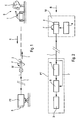
- Figure 1 illustrates, schematically, a system application of the process according to the present invention.
- Figure 2 is the block diagram of said system.
- FIG. 3 schematically illustrates the operation of the system Figures 1 and 2.
- FIG. 1 diagrammatically shows an attack missile M flying towards a target T, part of, with others E elements (only one is shown), a scene S.
- the missile M rotates about its longitudinal axis L-L, as illustrated by the circular arrow F of Figures 1 to 3.
- the M missile is launched and guided from a PT firing point, served by at least one operator (not shown).
- the missile M and the firing station PT are connected to each other by a link 1, allowing the exchange of information.
- a link 1 can be made by radio waves or by a cable, electrical or optical, taking place of said missile M.
- the missile M carries, in its front tip, a camera 2, by electronic example of CCD or CMOS type, observing the scene S, of which it receives light rays R.
- said missile M includes an illuminator - possibly incorporated in the camera 2-- illuminating said scene S, to which it addresses light rays I.
- the firing station comprises a display 3, on which the images of the scene S, taken by the camera 2 and transmitted display 3 by link 1.
- the gyroscopic system 4 is able to deliver the instantaneous value ⁇ of the angle of rotation of the missile M with respect to the vertical Z-Z ( Figure 3).
- the camera 2 is controlled by the gyroscopic system 4 so that, at each revolution of said missile around its longitudinal axis LL, said camera takes an image V 0 , V 90 , V 180 and V 270 of the scene S when the angle ⁇ takes values 0 °, 90 °, 180 ° and 270 ° (see Figure 3).
- camera 2 takes 20 to 40 frames per second.
- the shooting station PT comprises an acquisition device 5, receiving the images - in electronic form - taken by the camera 2 and transmitted by the link 1. It furthermore comprises a device geometric transformation of images 6, interposed between the device 5 and the display 3.
- the geometric transformation device of images may include, among others, the TMC 2301 component manufactured by the American TRW LSI and designated Image Resampling Sequencer.
- the geometric transformation device 6 is sequenced by sequencing signals from of the gyroscopic system 4 and conveyed by the link 1, as symbolized through the link 7.
- the views V 0, V '90, V' 180 and V '270 may appear in succession on the display 3 by giving the operator the impression of continuity of images of the scene S.
- the illumination means incorporated in the apparatus of Shooting 2 are put into operation to illuminate (light rays I) the scene S and increase the illumination of it in synchronism with the camera shots 2.
- These illumination means comprise advantageously a laser diode or a Vcsel laser as a component illumination.
Landscapes
- Engineering & Computer Science (AREA)
- Physics & Mathematics (AREA)
- General Physics & Mathematics (AREA)
- Theoretical Computer Science (AREA)
- Chemical & Material Sciences (AREA)
- Combustion & Propulsion (AREA)
- General Engineering & Computer Science (AREA)
- Closed-Circuit Television Systems (AREA)
- Studio Devices (AREA)
- Image Processing (AREA)
- Aiming, Guidance, Guns With A Light Source, Armor, Camouflage, And Targets (AREA)
- Processing Or Creating Images (AREA)
- Apparatus For Radiation Diagnosis (AREA)
- Analysing Materials By The Use Of Radiation (AREA)
- Stereoscopic And Panoramic Photography (AREA)
- Control Of Position, Course, Altitude, Or Attitude Of Moving Bodies (AREA)
- Length Measuring Devices By Optical Means (AREA)
Abstract
Description
- on fixe rigidement un appareil de prise de vues à l'avant dudit corps volant, de façon que ledit appareil de prise de vues tourne avec ledit corps volant autour dudit axe longitudinal ;
- pendant chaque tour de la rotation dudit corps volant autour dudit axe longitudinal, on prend, avec ledit appareil, plusieurs vues de ladite scène correspondant chacune à une position angulaire prédéterminée dudit corps volant autour dudit axe longitudinal, de sorte que les contours desdites vues sont inclinés de façons différentes les uns par rapport aux autres et que, dans chaque vue, l'image de ladite scène et ledit contour occupent une position relative qui dépend de ladite position angulaire prédéterminée correspondante dudit corps volant et qui est différente de celle des autres vues ;
- parmi lesdites vues, on détermine une vue de référence dans laquelle ladite position relative entre l'image de la scène et le contour est considérée comme une position relative de référence ;
- dans chaque vue, autre que la vue de référence, on applique à l'image de ladite scène un traitement de transformation géométrique d'image pour que la position relative de l'image transformée de ladite scène par rapport au contour soit semblable à ladite position relative de référence ; et
- on affiche successivement sur ledit afficheur ladite vue de référence et lesdites vues ayant subi ledit traitement de transformation géométrique d'image.
- au moins un corps volant, tournant autour de son axe longitudinal lorsqu'il vole ;
- un poste fixe, muni d'un afficheur apte à afficher des images successives d'une scène vers laquelle se déplace en tournant ledit corps volant ; et
- des moyens de liaison permettant les communications entre ledit corps volant et ledit poste fixe,
- un appareil de prise de vues, fixé rigidement à l'avant dudit corps volant pour observer ladite scène ;
- des moyens pour la commande dudit appareil de prise de vues à chacune de plusieurs positions angulaires prédéterminées dudit corps volant autour dudit axe longitudinal ; et
- des moyens de traitement de transformation géométrique d'image permettant de présenter les vues prises par ledit appareil à des positions angulaires différentes avec une position relative semblable de l'image de ladite scène par rapport au contour desdites vues.
- une vue de référence V0 sur laquelle apparaít l'image s (représentée uniquement par la silhouette de la cible T sur la figure 3) de la scène S, correspondant à =0°, dont le contour C présente un bord inférieur B et un bord supérieur H ;
- une vue V90 correspondant à = 90°, dont l'orientation a tourné de 90° par rapport à la vue de référence V0, de sorte que maintenant les bords latéraux gauche et droit du contour C de ladite vue V90 correspondent respectivement aux bords inférieur B et supérieur H du contour C de la vue de référence V0 ;
- une vue V180 correspondant à =180°, dont l'orientation a tourné de 180° par rapport à la vue de référence V0, de sorte que maintenant les bords supérieur et inférieur du contour C de ladite vue V180 correspondent respectivement aux bords inférieur B et supérieur H du contour C de la vue de référence V0 ; et
- une vue V270 correspondant à =270°, dont l'orientation a tourné de 270° par rapport à la vue de référence V0, de sorte que maintenant les bords latéraux gauche et droit du contour C de ladite vue V270 correspondent respectivement aux bords supérieur H et inférieur B du contour C de la vue de référence V0.
- par une transformation t1, la vue V90 en une vue V'90, dans laquelle l'image s de la scène S est tournée de 90°, de façon que les bords inférieur et supérieur du cadre C de cette vue V'90 correspondent respectivement aux bords inférieur B et supérieur H de la vue de référence V0 ;
- par une transformation t2, la vue V180 en une vue V'180, dans laquelle l'image s de la scène S est tournée de 180°, de façon que les bords inférieur et supérieur du cadre C de cette vue V'180 correspondent respectivement aux bords inférieur B et supérieur H de la vue de référence V0 ; et
- par une transformation t3, la vue V270 en une vue V'270, dans laquelle l'image s de la scène S est tournée de 270°, de façon que les bords inférieur et supérieur du cadre C de cette vue V'270 correspondent respectivement aux bords inférieur B et supérieur H de la vue de référence V0.
Claims (7)
- Procédé pour la formation, sur un afficheur (3) disposé à un poste fixe (PT), d'images successives (s) d'une scène (S) vers laquelle se déplace un corps volant (M) en rotation autour de son axe longitudinal (L-L), ledit corps volant (M) communiquant avec ledit poste fixe (PT) grâce à des moyens de liaison (1),
caractérisé en ce que :on fixe rigidement un appareil de prise de vues (2) à l'avant dudit corps volant (M), de façon que ledit appareil (2) tourne avec ledit corps volant (M) autour dudit axe longitudinal (L-L) ;pendant chaque tour de la rotation dudit corps volant (M) autour dudit axe longitudinal (L-L), on prend, avec ledit appareil (2), plusieurs vues de ladite scène (S) correspondant chacune à une position angulaire prédéterminée dudit corps volant autour dudit axe longitudinal, de sorte que les contours (C) desdites vues sont inclinés de façons différentes les uns par rapport aux autres et que, dans chaque vue, l'image (s) de ladite scène (S) et ledit contour (C) occupent une position relative qui dépend de ladite position angulaire prédéterminée correspondante dudit corps volant (M) et qui est différente de celle des autres vues ;parmi lesdites vues, on détermine une vue de référence (V0) dans laquelle ladite position relative entre l'image (s) de la scène (S) et le contour (C) est considérée comme une position relative de référence ;dans chaque vue, autre que la vue de référence, on applique à l'image (s) de ladite scène (S) un traitement de transformation géométrique d'image pour que la position relative de l'image transformée de ladite scène par rapport au contour soit semblable à ladite position relative de référence ; eton affiche successivement sur ledit afficheur (3) ladite vue de référence et lesdites vues ayant subi ledit traitement de transformation géométrique d'image. - Système comportant :caractérisé en ce qu'il comporte de plus :au moins un corps volant (M), tournant autour de son axe longitudinal (L-L) lorsqu'il vole ;un poste fixe (PT), muni d'un afficheur (3) apte à afficher des images d'une scène (S) vers laquelle se déplace en tournant ledit corps volant (M) ; etdes moyens de liaison (1) permettant les communications entre ledit corps volant (M) et ledit poste fixe (PT),un appareil de prise de vues (2), fixé rigidement à l'avant dudit corps volant (M) pour observer ladite scène (S) ;des moyens (4) pour la commande dudit appareil de prise de vues (2) à chacune de plusieurs positions angulaires prédéterminées dudit corps volant (M) autour dudit axe longitudinal (L-L) ; etdes moyens (6) de traitement de transformation géométrique d'image permettant de présenter les vues prises par ledit appareil (2) à des positions angulaires différentes avec une position relative semblable de l'image (s) de ladite scène (S) par rapport au contour (C) desdites vues.
- Système selon la revendication 2,
caractérisé en ce que lesdits moyens (4) de commande de l'appareil de prise de vues (2) sont constitués par un système gyroscopique monté à bord dudit corps volant (M) et sensible à la rotation de ce dernier contour de son axe longitudinal (L-L. - Système selon l'une des revendications 2 ou 3,
caractérisé en ce que lesdits moyens de traitement d'image (6) sont disposés au poste fixe (PT). - Système selon la revendication 4,
caractérisé en ce que la liaison entre ledit appareil de prise de vues (2) et lesdits moyens de traitement d'image (6) est réalisée par lesdits moyens de liaison (1) entre ledit corps volant (M) et ledit poste fixe (PT). - Système selon les revendications 3 et 4,
caractérisé en ce que le séquencement du fonctionnement desdits moyens de traitement d'image (6) est commandé par ledit système gyroscopique (4) par l'intermédiaire desdits moyens de liaison (1) entre ledit corps volant (M) et ledit poste fixe (PT). - Système selon l'une des revendications 2 à 6,
caractérisé en ce qu'il comporte des moyens d'illumination (2), montés à bord dudit corps volant (M) et aptes à éclairer ladite scène (S).
Applications Claiming Priority (2)
| Application Number | Priority Date | Filing Date | Title |
|---|---|---|---|
| FR0311659 | 2003-10-06 | ||
| FR0311659A FR2860623B1 (fr) | 2003-10-06 | 2003-10-06 | Procede de prise de vues a bord d'un corps volant tournant et systeme le mettant en oeuvre. |
Publications (2)
| Publication Number | Publication Date |
|---|---|
| EP1522960A1 true EP1522960A1 (fr) | 2005-04-13 |
| EP1522960B1 EP1522960B1 (fr) | 2016-10-19 |
Family
ID=34307438
Family Applications (1)
| Application Number | Title | Priority Date | Filing Date |
|---|---|---|---|
| EP04292243.5A Expired - Lifetime EP1522960B1 (fr) | 2003-10-06 | 2004-09-20 | Procédé de prise de vues à bord d'un corps volant tournant et système le mettant en oeuvre |
Country Status (11)
| Country | Link |
|---|---|
| US (1) | US7672480B2 (fr) |
| EP (1) | EP1522960B1 (fr) |
| JP (1) | JP4621677B2 (fr) |
| KR (1) | KR101066645B1 (fr) |
| CN (1) | CN1864174B (fr) |
| ES (1) | ES2610459T3 (fr) |
| FR (1) | FR2860623B1 (fr) |
| IL (1) | IL173996A (fr) |
| NO (1) | NO340449B1 (fr) |
| WO (1) | WO2005036458A1 (fr) |
| ZA (1) | ZA200602572B (fr) |
Families Citing this family (4)
| Publication number | Priority date | Publication date | Assignee | Title |
|---|---|---|---|---|
| CN101753995A (zh) * | 2009-12-31 | 2010-06-23 | 上海杰远环保科技有限公司 | 一种数字型标杆发射系统 |
| IL217621A0 (en) * | 2012-01-18 | 2012-03-29 | Rafael Advanced Defense Sys | Laser target seeker with photodetector and image sensor |
| EP3674214A1 (fr) * | 2014-10-17 | 2020-07-01 | Sony Corporation | Dispositif de commande, procédé de commande et dispositif de véhicule volant |
| KR101746636B1 (ko) | 2015-04-17 | 2017-06-14 | (주)티아이랩 | 무인 항공기의 야간 촬영을 위한 조명 위치 결정 시스템 및 방법 |
Citations (6)
| Publication number | Priority date | Publication date | Assignee | Title |
|---|---|---|---|---|
| US4637571A (en) * | 1985-09-03 | 1987-01-20 | The United States Of America As Represented By The Secretary Of The Army | Electronic image stabilization |
| US4796834A (en) * | 1980-09-15 | 1989-01-10 | U.S. Philips Corporation | Method for combatting of targets and projectile or missile for carrying out the method |
| EP0447080A1 (fr) * | 1990-03-10 | 1991-09-18 | United Kingdom Atomic Energy Authority | Dispositif de reconnaissance |
| US5173945A (en) * | 1989-12-28 | 1992-12-22 | Aerospatiale Societe Nationale Industrielle | Process and apparatus for estimating the movement of a moving object |
| US5577182A (en) * | 1993-10-26 | 1996-11-19 | Fuji Xerox Co., Ltd. | Image processing apparatus |
| EP0948197A2 (fr) * | 1998-04-03 | 1999-10-06 | Zeiss Optronik GmbH | Dispositif et procédé pour la stabilisation d'image numérique |
Family Cites Families (8)
| Publication number | Priority date | Publication date | Assignee | Title |
|---|---|---|---|---|
| FR754790A (fr) * | 1933-04-26 | 1933-11-14 | Smith & Sons Ltd S | Perfectionnements aux horloges à commande électrique |
| US4267562A (en) * | 1977-10-18 | 1981-05-12 | The United States Of America As Represented By The Secretary Of The Army | Method of autonomous target acquisition |
| FR2536851B1 (fr) * | 1982-11-30 | 1985-06-14 | Aerospatiale | Systeme de reconnaissance comportant un vehicule aerien tournant autour de son axe longitudinal |
| US4639571A (en) * | 1985-11-29 | 1987-01-27 | The United States Of America As Represented By The United States Department Of Energy | Method of beam welding metallic parts together and apparatus for doing same |
| CN1181308C (zh) * | 2000-07-24 | 2004-12-22 | 长春师凯科技产业有限责任公司 | 一种抗强光干扰的制导方法 |
| JP2003085541A (ja) * | 2001-09-06 | 2003-03-20 | Starlabo Corp | 航空機搭載撮像装置 |
| JP2003101848A (ja) * | 2001-09-19 | 2003-04-04 | Matsushita Electric Ind Co Ltd | 電子スチルカメラ装置 |
| US7263206B1 (en) * | 2002-05-10 | 2007-08-28 | Randy L. Milbert | Differentiating friend from foe and assessing threats in a soldier's head-mounted display |
-
2003
- 2003-10-06 FR FR0311659A patent/FR2860623B1/fr not_active Expired - Fee Related
-
2004
- 2004-09-20 EP EP04292243.5A patent/EP1522960B1/fr not_active Expired - Lifetime
- 2004-09-20 ES ES04292243.5T patent/ES2610459T3/es not_active Expired - Lifetime
- 2004-10-05 US US10/574,521 patent/US7672480B2/en not_active Expired - Fee Related
- 2004-10-05 JP JP2006530416A patent/JP4621677B2/ja not_active Expired - Fee Related
- 2004-10-05 KR KR1020067006552A patent/KR101066645B1/ko not_active Expired - Fee Related
- 2004-10-05 WO PCT/FR2004/002507 patent/WO2005036458A1/fr not_active Ceased
- 2004-10-05 CN CN2004800291957A patent/CN1864174B/zh not_active Expired - Fee Related
-
2006
- 2006-02-28 IL IL173996A patent/IL173996A/en active IP Right Grant
- 2006-03-29 ZA ZA200602572A patent/ZA200602572B/en unknown
- 2006-05-05 NO NO20062023A patent/NO340449B1/no not_active IP Right Cessation
Patent Citations (6)
| Publication number | Priority date | Publication date | Assignee | Title |
|---|---|---|---|---|
| US4796834A (en) * | 1980-09-15 | 1989-01-10 | U.S. Philips Corporation | Method for combatting of targets and projectile or missile for carrying out the method |
| US4637571A (en) * | 1985-09-03 | 1987-01-20 | The United States Of America As Represented By The Secretary Of The Army | Electronic image stabilization |
| US5173945A (en) * | 1989-12-28 | 1992-12-22 | Aerospatiale Societe Nationale Industrielle | Process and apparatus for estimating the movement of a moving object |
| EP0447080A1 (fr) * | 1990-03-10 | 1991-09-18 | United Kingdom Atomic Energy Authority | Dispositif de reconnaissance |
| US5577182A (en) * | 1993-10-26 | 1996-11-19 | Fuji Xerox Co., Ltd. | Image processing apparatus |
| EP0948197A2 (fr) * | 1998-04-03 | 1999-10-06 | Zeiss Optronik GmbH | Dispositif et procédé pour la stabilisation d'image numérique |
Also Published As
| Publication number | Publication date |
|---|---|
| WO2005036458A1 (fr) | 2005-04-21 |
| ZA200602572B (en) | 2007-05-30 |
| NO340449B1 (no) | 2017-04-24 |
| EP1522960B1 (fr) | 2016-10-19 |
| KR20060121896A (ko) | 2006-11-29 |
| CN1864174A (zh) | 2006-11-15 |
| JP4621677B2 (ja) | 2011-01-26 |
| FR2860623A1 (fr) | 2005-04-08 |
| NO20062023L (no) | 2006-06-23 |
| ES2610459T3 (es) | 2017-04-27 |
| US7672480B2 (en) | 2010-03-02 |
| KR101066645B1 (ko) | 2011-09-22 |
| IL173996A (en) | 2010-12-30 |
| IL173996A0 (en) | 2006-07-05 |
| FR2860623B1 (fr) | 2005-12-30 |
| CN1864174B (zh) | 2013-03-27 |
| US20070040853A1 (en) | 2007-02-22 |
| JP2007514116A (ja) | 2007-05-31 |
Similar Documents
| Publication | Publication Date | Title |
|---|---|---|
| EP0033679B1 (fr) | Système de désignation d'objectif par laser | |
| FR2459496A2 (fr) | Appareil photographique rapporte pour microscopes | |
| EP0100719A1 (fr) | Dispositif de simulation de tir pour l'entraînement à la manoeuvre d'armes épaulables ou analogues | |
| FR2719659A1 (fr) | Procédé et dispositif de correction de la trajectoire de projectiles. | |
| FR2761463A1 (fr) | Dispositif de conduite de tir pour systeme de defense antiaerienne, notamment mobile | |
| EP1522960B1 (fr) | Procédé de prise de vues à bord d'un corps volant tournant et système le mettant en oeuvre | |
| FR2706721A1 (fr) | Procédé et dispositif pour déterminer la localisation d'une cible. | |
| FR2712993A1 (fr) | Système de vision. | |
| FR2644905A1 (fr) | Appareil photographique reflex mono-objectif avec telemetre a triangulation et flash | |
| CA2300577C (fr) | Dispositif d'emission d'images video numeriques | |
| FR2569838A1 (fr) | Dispositif de mesure pour determiner la position relative de deux corps | |
| EP0740123B1 (fr) | Système pour déterminer la position et l'angle de roulis d'un mobile | |
| FR2780774A1 (fr) | Dispositif d'autoprotection passive pour engin mobile tel qu'un helicoptere | |
| EP0127914B1 (fr) | Viseur panoramique sans rotation d'image à plusieurs champs | |
| FR2602389A1 (fr) | Systeme pour ajuster les positions angulaires relatives de deux cameras video dirigees vers un meme objet et son application au reglage de l'orientation de deux appareils | |
| FR2530009A1 (fr) | Appareil de visee panoramique stabilisee comprenant un detecteur thermique | |
| EP0452188B1 (fr) | Dispositif d'imagerie et de surveillance à détecteur matriciel | |
| EP0090713B1 (fr) | Système de conduite de tir à lunette d'observation asservie par un dispositif de poursuite automatique | |
| FR3070497B1 (fr) | Instrument d'imagerie pour controler une designation de cible | |
| CA2681927A1 (fr) | Procede et dispositif a deux lasers pour la detection de systemes optiques grossissants | |
| FR2551195A1 (fr) | Dispositif pour le guidage d'un missile sur un objectif | |
| FR2665251A1 (fr) | Systeme de guidage pour missiles. | |
| EP0418132B1 (fr) | Dispositif pour la détection de cibles | |
| FR2623636A1 (fr) | Dispositif de visee opto-electronique | |
| EP1112653B1 (fr) | Camera cinevideo |
Legal Events
| Date | Code | Title | Description |
|---|---|---|---|
| PUAI | Public reference made under article 153(3) epc to a published international application that has entered the european phase |
Free format text: ORIGINAL CODE: 0009012 |
|
| AK | Designated contracting states |
Kind code of ref document: A1 Designated state(s): AT BE BG CH CY CZ DE DK EE ES FI FR GB GR HU IE IT LI LU MC NL PL PT RO SE SI SK TR |
|
| AX | Request for extension of the european patent |
Extension state: AL HR LT LV MK |
|
| 17P | Request for examination filed |
Effective date: 20050506 |
|
| AKX | Designation fees paid |
Designated state(s): AT BE BG CH CY CZ DE DK EE ES FI FR GB GR HU IE IT LI LU MC NL PL PT RO SE SI SK TR |
|
| 17Q | First examination report despatched |
Effective date: 20070117 |
|
| GRAP | Despatch of communication of intention to grant a patent |
Free format text: ORIGINAL CODE: EPIDOSNIGR1 |
|
| INTG | Intention to grant announced |
Effective date: 20160610 |
|
| GRAS | Grant fee paid |
Free format text: ORIGINAL CODE: EPIDOSNIGR3 |
|
| GRAA | (expected) grant |
Free format text: ORIGINAL CODE: 0009210 |
|
| AK | Designated contracting states |
Kind code of ref document: B1 Designated state(s): AT BE BG CH CY CZ DE DK EE ES FI FR GB GR HU IE IT LI LU MC NL PL PT RO SE SI SK TR |
|
| REG | Reference to a national code |
Ref country code: GB Ref legal event code: FG4D Free format text: NOT ENGLISH |
|
| REG | Reference to a national code |
Ref country code: DE Ref legal event code: R081 Ref document number: 602004050151 Country of ref document: DE Owner name: MBDA FRANCE, FR Free format text: FORMER OWNER: MBDA FRANCE, PARIS, FR |
|
| REG | Reference to a national code |
Ref country code: CH Ref legal event code: EP |
|
| REG | Reference to a national code |
Ref country code: AT Ref legal event code: REF Ref document number: 838903 Country of ref document: AT Kind code of ref document: T Effective date: 20161115 |
|
| REG | Reference to a national code |
Ref country code: IE Ref legal event code: FG4D Free format text: LANGUAGE OF EP DOCUMENT: FRENCH |
|
| REG | Reference to a national code |
Ref country code: DE Ref legal event code: R096 Ref document number: 602004050151 Country of ref document: DE |
|
| REG | Reference to a national code |
Ref country code: DE Ref legal event code: R081 Ref document number: 602004050151 Country of ref document: DE Owner name: MBDA FRANCE, FR Free format text: FORMER OWNER: MBDA FRANCE, PARIS, FR |
|
| RAP2 | Party data changed (patent owner data changed or rights of a patent transferred) |
Owner name: MBDA FRANCE |
|
| REG | Reference to a national code |
Ref country code: NL Ref legal event code: MP Effective date: 20161019 |
|
| REG | Reference to a national code |
Ref country code: AT Ref legal event code: MK05 Ref document number: 838903 Country of ref document: AT Kind code of ref document: T Effective date: 20161019 |
|
| REG | Reference to a national code |
Ref country code: ES Ref legal event code: FG2A Ref document number: 2610459 Country of ref document: ES Kind code of ref document: T3 Effective date: 20170427 |
|
| PG25 | Lapsed in a contracting state [announced via postgrant information from national office to epo] |
Ref country code: SE Free format text: LAPSE BECAUSE OF FAILURE TO SUBMIT A TRANSLATION OF THE DESCRIPTION OR TO PAY THE FEE WITHIN THE PRESCRIBED TIME-LIMIT Effective date: 20161019 Ref country code: GR Free format text: LAPSE BECAUSE OF FAILURE TO SUBMIT A TRANSLATION OF THE DESCRIPTION OR TO PAY THE FEE WITHIN THE PRESCRIBED TIME-LIMIT Effective date: 20170120 |
|
| PG25 | Lapsed in a contracting state [announced via postgrant information from national office to epo] |
Ref country code: AT Free format text: LAPSE BECAUSE OF FAILURE TO SUBMIT A TRANSLATION OF THE DESCRIPTION OR TO PAY THE FEE WITHIN THE PRESCRIBED TIME-LIMIT Effective date: 20161019 Ref country code: PT Free format text: LAPSE BECAUSE OF FAILURE TO SUBMIT A TRANSLATION OF THE DESCRIPTION OR TO PAY THE FEE WITHIN THE PRESCRIBED TIME-LIMIT Effective date: 20170220 Ref country code: PL Free format text: LAPSE BECAUSE OF FAILURE TO SUBMIT A TRANSLATION OF THE DESCRIPTION OR TO PAY THE FEE WITHIN THE PRESCRIBED TIME-LIMIT Effective date: 20161019 Ref country code: FI Free format text: LAPSE BECAUSE OF FAILURE TO SUBMIT A TRANSLATION OF THE DESCRIPTION OR TO PAY THE FEE WITHIN THE PRESCRIBED TIME-LIMIT Effective date: 20161019 Ref country code: NL Free format text: LAPSE BECAUSE OF FAILURE TO SUBMIT A TRANSLATION OF THE DESCRIPTION OR TO PAY THE FEE WITHIN THE PRESCRIBED TIME-LIMIT Effective date: 20161019 |
|
| REG | Reference to a national code |
Ref country code: DE Ref legal event code: R097 Ref document number: 602004050151 Country of ref document: DE |
|
| PG25 | Lapsed in a contracting state [announced via postgrant information from national office to epo] |
Ref country code: DK Free format text: LAPSE BECAUSE OF FAILURE TO SUBMIT A TRANSLATION OF THE DESCRIPTION OR TO PAY THE FEE WITHIN THE PRESCRIBED TIME-LIMIT Effective date: 20161019 Ref country code: CZ Free format text: LAPSE BECAUSE OF FAILURE TO SUBMIT A TRANSLATION OF THE DESCRIPTION OR TO PAY THE FEE WITHIN THE PRESCRIBED TIME-LIMIT Effective date: 20161019 Ref country code: EE Free format text: LAPSE BECAUSE OF FAILURE TO SUBMIT A TRANSLATION OF THE DESCRIPTION OR TO PAY THE FEE WITHIN THE PRESCRIBED TIME-LIMIT Effective date: 20161019 Ref country code: SK Free format text: LAPSE BECAUSE OF FAILURE TO SUBMIT A TRANSLATION OF THE DESCRIPTION OR TO PAY THE FEE WITHIN THE PRESCRIBED TIME-LIMIT Effective date: 20161019 Ref country code: RO Free format text: LAPSE BECAUSE OF FAILURE TO SUBMIT A TRANSLATION OF THE DESCRIPTION OR TO PAY THE FEE WITHIN THE PRESCRIBED TIME-LIMIT Effective date: 20161019 |
|
| PLBE | No opposition filed within time limit |
Free format text: ORIGINAL CODE: 0009261 |
|
| STAA | Information on the status of an ep patent application or granted ep patent |
Free format text: STATUS: NO OPPOSITION FILED WITHIN TIME LIMIT |
|
| PG25 | Lapsed in a contracting state [announced via postgrant information from national office to epo] |
Ref country code: BG Free format text: LAPSE BECAUSE OF FAILURE TO SUBMIT A TRANSLATION OF THE DESCRIPTION OR TO PAY THE FEE WITHIN THE PRESCRIBED TIME-LIMIT Effective date: 20170119 |
|
| 26N | No opposition filed |
Effective date: 20170720 |
|
| REG | Reference to a national code |
Ref country code: FR Ref legal event code: PLFP Year of fee payment: 14 |
|
| PG25 | Lapsed in a contracting state [announced via postgrant information from national office to epo] |
Ref country code: SI Free format text: LAPSE BECAUSE OF FAILURE TO SUBMIT A TRANSLATION OF THE DESCRIPTION OR TO PAY THE FEE WITHIN THE PRESCRIBED TIME-LIMIT Effective date: 20161019 |
|
| REG | Reference to a national code |
Ref country code: CH Ref legal event code: PL |
|
| PG25 | Lapsed in a contracting state [announced via postgrant information from national office to epo] |
Ref country code: MC Free format text: LAPSE BECAUSE OF FAILURE TO SUBMIT A TRANSLATION OF THE DESCRIPTION OR TO PAY THE FEE WITHIN THE PRESCRIBED TIME-LIMIT Effective date: 20161019 |
|
| REG | Reference to a national code |
Ref country code: IE Ref legal event code: MM4A |
|
| REG | Reference to a national code |
Ref country code: BE Ref legal event code: MM Effective date: 20170930 |
|
| PG25 | Lapsed in a contracting state [announced via postgrant information from national office to epo] |
Ref country code: LU Free format text: LAPSE BECAUSE OF NON-PAYMENT OF DUE FEES Effective date: 20170920 |
|
| PG25 | Lapsed in a contracting state [announced via postgrant information from national office to epo] |
Ref country code: CH Free format text: LAPSE BECAUSE OF NON-PAYMENT OF DUE FEES Effective date: 20170930 Ref country code: LI Free format text: LAPSE BECAUSE OF NON-PAYMENT OF DUE FEES Effective date: 20170930 Ref country code: IE Free format text: LAPSE BECAUSE OF NON-PAYMENT OF DUE FEES Effective date: 20170920 |
|
| PG25 | Lapsed in a contracting state [announced via postgrant information from national office to epo] |
Ref country code: BE Free format text: LAPSE BECAUSE OF NON-PAYMENT OF DUE FEES Effective date: 20170930 |
|
| REG | Reference to a national code |
Ref country code: FR Ref legal event code: PLFP Year of fee payment: 15 |
|
| PG25 | Lapsed in a contracting state [announced via postgrant information from national office to epo] |
Ref country code: HU Free format text: LAPSE BECAUSE OF FAILURE TO SUBMIT A TRANSLATION OF THE DESCRIPTION OR TO PAY THE FEE WITHIN THE PRESCRIBED TIME-LIMIT; INVALID AB INITIO Effective date: 20040920 |
|
| PG25 | Lapsed in a contracting state [announced via postgrant information from national office to epo] |
Ref country code: CY Free format text: LAPSE BECAUSE OF NON-PAYMENT OF DUE FEES Effective date: 20161019 |
|
| PG25 | Lapsed in a contracting state [announced via postgrant information from national office to epo] |
Ref country code: TR Free format text: LAPSE BECAUSE OF FAILURE TO SUBMIT A TRANSLATION OF THE DESCRIPTION OR TO PAY THE FEE WITHIN THE PRESCRIBED TIME-LIMIT Effective date: 20161019 |
|
| PGFP | Annual fee paid to national office [announced via postgrant information from national office to epo] |
Ref country code: DE Payment date: 20200910 Year of fee payment: 17 Ref country code: FR Payment date: 20200930 Year of fee payment: 17 Ref country code: GB Payment date: 20200921 Year of fee payment: 17 |
|
| PGFP | Annual fee paid to national office [announced via postgrant information from national office to epo] |
Ref country code: IT Payment date: 20200911 Year of fee payment: 17 |
|
| PGFP | Annual fee paid to national office [announced via postgrant information from national office to epo] |
Ref country code: ES Payment date: 20201009 Year of fee payment: 17 |
|
| REG | Reference to a national code |
Ref country code: DE Ref legal event code: R119 Ref document number: 602004050151 Country of ref document: DE |
|
| GBPC | Gb: european patent ceased through non-payment of renewal fee |
Effective date: 20210920 |
|
| PG25 | Lapsed in a contracting state [announced via postgrant information from national office to epo] |
Ref country code: GB Free format text: LAPSE BECAUSE OF NON-PAYMENT OF DUE FEES Effective date: 20210920 Ref country code: FR Free format text: LAPSE BECAUSE OF NON-PAYMENT OF DUE FEES Effective date: 20210930 Ref country code: DE Free format text: LAPSE BECAUSE OF NON-PAYMENT OF DUE FEES Effective date: 20220401 |
|
| REG | Reference to a national code |
Ref country code: ES Ref legal event code: FD2A Effective date: 20221028 |
|
| PG25 | Lapsed in a contracting state [announced via postgrant information from national office to epo] |
Ref country code: IT Free format text: LAPSE BECAUSE OF NON-PAYMENT OF DUE FEES Effective date: 20210920 |
|
| PG25 | Lapsed in a contracting state [announced via postgrant information from national office to epo] |
Ref country code: ES Free format text: LAPSE BECAUSE OF NON-PAYMENT OF DUE FEES Effective date: 20210921 |