EP1522936A2 - Constructions géométriques et méthodes associées de modelisation Monte-Carlo - Google Patents
Constructions géométriques et méthodes associées de modelisation Monte-Carlo Download PDFInfo
- Publication number
- EP1522936A2 EP1522936A2 EP04256175A EP04256175A EP1522936A2 EP 1522936 A2 EP1522936 A2 EP 1522936A2 EP 04256175 A EP04256175 A EP 04256175A EP 04256175 A EP04256175 A EP 04256175A EP 1522936 A2 EP1522936 A2 EP 1522936A2
- Authority
- EP
- European Patent Office
- Prior art keywords
- geometric
- region
- modeling
- modeled
- embedded
- Prior art date
- Legal status (The legal status is an assumption and is not a legal conclusion. Google has not performed a legal analysis and makes no representation as to the accuracy of the status listed.)
- Ceased
Links
Images


Classifications
-
- G—PHYSICS
- G21—NUCLEAR PHYSICS; NUCLEAR ENGINEERING
- G21C—NUCLEAR REACTORS
- G21C19/00—Arrangements for treating, for handling, or for facilitating the handling of, fuel or other materials which are used within the reactor, e.g. within its pressure vessel
- G21C19/40—Arrangements for preventing occurrence of critical conditions, e.g. during storage
-
- G—PHYSICS
- G06—COMPUTING OR CALCULATING; COUNTING
- G06F—ELECTRIC DIGITAL DATA PROCESSING
- G06F30/00—Computer-aided design [CAD]
-
- G—PHYSICS
- G06—COMPUTING OR CALCULATING; COUNTING
- G06F—ELECTRIC DIGITAL DATA PROCESSING
- G06F2111/00—Details relating to CAD techniques
- G06F2111/08—Probabilistic or stochastic CAD
-
- Y—GENERAL TAGGING OF NEW TECHNOLOGICAL DEVELOPMENTS; GENERAL TAGGING OF CROSS-SECTIONAL TECHNOLOGIES SPANNING OVER SEVERAL SECTIONS OF THE IPC; TECHNICAL SUBJECTS COVERED BY FORMER USPC CROSS-REFERENCE ART COLLECTIONS [XRACs] AND DIGESTS
- Y02—TECHNOLOGIES OR APPLICATIONS FOR MITIGATION OR ADAPTATION AGAINST CLIMATE CHANGE
- Y02E—REDUCTION OF GREENHOUSE GAS [GHG] EMISSIONS, RELATED TO ENERGY GENERATION, TRANSMISSION OR DISTRIBUTION
- Y02E30/00—Energy generation of nuclear origin
- Y02E30/30—Nuclear fission reactors
Definitions
- This invention relates to modeling fissile systems for providing nuclear criticality analyses.
- Nuclear criticality analyses such as criticality analyses of shipping containers, process equipment, and facility process equipment interactions, for example, are used to ensure acceptable safety levels in, for example, nuclear fuel processing facilities.
- geometric modeling may be provided in connection with Monte Carlo methods for evaluating the various interactions within a fissile system.
- Geometric modeling for use with Monte Carlo methods has become a primary analytical tool in nuclear criticality safety analyses, with the use of such geometric modeling extended more frequently to complex structures and arrays.
- increased regulatory requirements especially in analyses of shipping containers and equipment, process or facility interactions has increased the need for using such geometric modeling in connection with Monte Carlo methods for providing criticality analyses. Further, this analyses often requires complex modeling of areas of fissile systems with little or no geometric symmetry.
- k-effective represents the degree to which the neutron population is either increasing or decreasing, thus indicating whether the defined fissile system being modeled approaches or exceeds a sustained nuclear chain reaction.
- k-effective represents the degree to which the neutron population is either increasing or decreasing, thus indicating whether the defined fissile system being modeled approaches or exceeds a sustained nuclear chain reaction.
- a system that exceeds a sustained nuclear chain reaction is said to be "supercritical” and is identified by a k-effective > 1.0.
- a system that just reaches a sustained nuclear chain reaction is said to be “critical” and is identified by a k-effective that is exactly equal to 1.00.
- k-effective is ⁇ 1.0 (e.g., "subcritical") with an adequate safety margin such that even under accident conditions the system remains subcritical.
- Monte Carlo methods to track neutrons through a model of a fissile system to estimate k-effective, a determination may be made as to whether the modeled fissile system is, for example, critical, supercritical or subcritical.
- Analytic approaches to modeling fissile systems using Monte Carlo methods are limited in their ability to model the precise geometries involved.
- these analytic methods are limited in their ability to model complex geometries (e.g., triangular lattices of rods and spheres), as well as in their ability to combine the various geometries (e.g., combine overlapping lattices).
- the size of rods and spheres may become very small under optimum conditions, requiring the modeling of large numbers of rods or spheres.
- the complexity and difficulty of the modeling increases rapidly when small-dimensioned geometric shapes are required to entirely fill a much larger region.
- various geometric constructs are configured for use in modeling a system, for example a fissile system, using an analysis method, such as Monte Carlo, to model such systems based upon the interstitial regions formed by these geometric constructs.
- the various geometric constructs are configured to provide for modeling of, for example, complex arrays and lattices and allows for embedding of these constructs and virtual filling of arrays of these modeled constructs.
- exemplary embodiments of the present invention are merely exemplary in nature and is in no way intended to limit the invention, its application, or uses.
- exemplary embodiments of the present invention are described in connection with a modeling system having particular geometric structures and geometric modeling methods and functionality for use in modeling fissile systems in order to perform a criticality analysis, they are not so limited, and variations and modifications to the geometric structures and geometric modeling methods and functionality may be provided to model different systems in order to perform different analyses.
- Fig. 1 is a block diagram of an analytic system in accordance with the exemplary embodiments of the present invention.
- Fig. 1 illustrates an exemplary analytic system 20, which may be configured, for example, as a Monte Carlo neutronics program that may be used to obtain a solution to a neutron transport equation by tracking neutrons through a computer model of a fissile system.
- Various exemplary embodiments of modeling structures (e.g., geometric constructs) and analytic methods of the present invention may be implemented in connection with the analytic system 20.
- the analytic system 20 includes a modeling component 22 connected to a database 24.
- the modeling component 22 is configured to receive input parameters, for example, relating to a fissile system to be modeled for analyses, and process the input parameters (e.g., specifics regarding materials, such as composition, and dimensions of physical structures to be modeled) using information stored within the database 24 (e.g., properties for geometric units relating to the input parameters), and provide an output, such as a determination (e.g., estimate) of the neutron multiplication factor (k-effective) for the modeled fissile system.
- a criticality analyses of a modeled system e.g., nuclear fuel process, equipment, or facility
- neutrons are tracked through a system modeled by the modeling component 22. For example, a starting point for each neutron in a batch is selected. The mean free path ( ⁇ ) is then obtained for a neutron based on event probabilities in, for example, a cross-section library for the material it is passing through, which information may be stored within the database 24.
- the analytic system 20 then advances the neutron using a known process (e.g., using a Monte Carlo program such as GEKENO or GEMER) to the collision point in the material, or advances the neutron to the closest boundary that exists along a path ahead of the collision point.
- a known process e.g., using a Monte Carlo program such as GEKENO or GEMER
- the contribution to fission is the product of the path length times the macroscopic cross-section for fission times the neutron weight.
- the neutron weight is a fraction that allows some of the neutron to be absorbed and the remainder to continue to be tracked by a tracking process.
- the contribution to absorption is the product of the path length times the macroscopic cross-section for absorption times the neutron weight.
- the neutron weight e.g., the fraction that allows some of the neutron to be absorbed and the remainder to continue to be tracked by the tracking process
- the neutron weight is then reduced by the probability of absorption. If the weight drops below a minimum value, then the neutron is randomly either (a) doubled in weight; or (b) removed entirely from the system being modeled (e.g., Russian Roulette). If the neutron is advanced to a new position in the material, a new set of tracking information (e.g., direction cosines and mean free path) are determined and the tracking process repeats. If the neutron is advanced to a boundary, a new mean free path and event probabilities are obtained for the new material and the tracking process repeats.
- tracking information e.g., direction cosines and mean free path
- the position is entered into a starting source array for the next batch (e.g., next batch of neutron collision trackings) with the current weight.
- This position entering process is repeated until the neutron is removed from the system (e.g., neutron is eliminated or leaks from the modeled system).
- the process is then repeated for the rest of the neutrons in the batch.
- the next batch is then processed using the starting source array generated by the current batch.
- the Monte Carlo neutron transport calculations terminate.
- the modeling of the system thereby enables determination of the relative criticality safety (subcritical margin) of the system, and more particularly, a calculation of the estimate of k-effective, the effective neutron multiplication for the modeled system.
- a region e.g., box type
- each region may be defined by a geometry type descriptor, a mixture number identifying the material within the region, a set of dimensions for the region and a set of region dependent weights.
- a plurality of selectable geometry types may be provided for use by the modeling component 22 in connection with the input parameters to model a fissile system, for example.
- the following exemplary geometric units or structures may be provided:
- geometric units or structures may be provided as desired or needed, for example, as a predetermined set of geometric constructs included as part of a known Monte Carlo neutron transport program. Further, and as described in more detail herein, these geometric structures generally allow for forming square (or triangular) pitches when modeling systems with lattice geometry configurations.
- analytic system 20 with a modeling component 22, which may be used for Monte Carlo neutron transport evaluations of fissile systems for providing a criticality analysis for example, various exemplary embodiments of modeling structures and methods of the present invention that may be provided in connection with the modeling component 22 as part of the analytic system 20 will now be described.
- the various embodiments, for example, may be incorporated into Monte Carlo neutron transport analytic methods for use separately or in conjunction with each other to model, for example, complex arrays, lattices and assemblies.
- various geometric constructs may be provided for use in connection with the modeling component 22.
- these geometric constructs are configured to allow for modeling in simple rectangular boxes, parts of the unit components of triangular and body-centered cubic lattices, such that, for example, complete lattices may be constructed at the surfaces of the boxes using appropriate reflective boundary conditions.
- These geometric constructs are generally configured having curved concave portions (e.g., concave surfaces) for modeling of systems (e.g., fissile systems) using the modeling component 22 in Fig. 1. Interstitial regions formed by the curved concave portions when arranging (e.g., combining) the geometric constructs create the various elements or objects of a system being modeled and allow for forming the elements or objects in a triangular pitch.
- Figs. 2A and 2B are side perspective views of an exemplary embodiment of the present invention.
- a first geometric unit 50 and 50' may provide a three-dimensional rectangular region 52 (e.g., rectangular body) that can be used for modeling a triangular lattice of cylindrical rods in a given matrix (e.g., water).
- a given matrix e.g., water
- exemplary embodiments of the first geometric unit 50 and 50' are configured such that the three-dimensional rectangular body 52 includes two opposite edges 54 and 56 that are modified in opposite corners 56 (e.g., corners removed), and more particularly, having a curved (e.g., concave) portion 58 configured equivalent to, for example, the shape of one-fourth of a cylinder (i.e., concave portion representing one-fourth of a cylinder shape removed from the opposite corners 54 and 56) formed thereon.
- the overall geometry is an infinite triangular lattice of, for example, fuel cylinders as described herein.
- an infinite triangular lattice of fuel cylinders in an alternating grid can also be created by stacking the first geometric units 50 and 50' (represented by +1 and -1) in both the X and Y directions as shown in Fig. 5.
- cylindrical arrays for modeling formed by interstitial regions of the first geometric units 50 and 50' may be provided using, for example, the following input: Mix No., X/4, Y/2, Radius, Sign, +Z, -Z
- first geometric units 50 and 50' and for example, a complete lattice unit cell may be modeled in a triangular orientation or pitch as shown in Figs. 12-14.
- the first geometric units 50 and 50' may be used with reflective boundary conditions on all six sides, or with two separate box types specified alternately in the X and Y directions, one of which is the descriptor for the +1 missing edges and the other is the -1 missing edges.
- the first geometric units 50 and 50' having +1 and -1 missing edges are shown in Figs. 15A and 15B.
- first geometric units 50 and 50' may be used for modeling cylinders formed by interstitial regions (i.e., created by the concave portions 58) between first geometric units 50 and 50' arranged as described herein.
- Fig. 3 is a side perspective view of another exemplary embodiment of a geometric construct of the present invention.
- a second geometric unit 70 provides a three dimensional rectangular region (e.g., rectangular body) for modeling body-centered cubic lattices or arrays of spherical particles in a given matrix (e.g., water).
- an exemplary embodiment of the second geometric unit 70 includes a generally cubic body 72 with two opposite corners 74 having curved (e.g., concave) portions 76 on two oppositely facing surfaces 75 forming sides 78, configured, for example as the shape of one-eighth of a sphere (i.e., curved portion 76 representing one-eighth of a spherical shape removed from the opposite corners 74).
- curved portions 76 representing one-eighth of a spherical shape removed from the opposite corners 74.
- spherical arrays for modeling formed by the interstitial regions of the second geometric unit 70 may be provided using, for example, the following input: Mix No., SIDE/2, Radius
- the second geometric unit 70 may be used for modeling configurations of spheres.
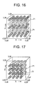
- Fig. 16 is a perspective view of a simple cubic array of spheres for illustrative purposes.
- Fig. 17 is a perspective view of a body-centered cubic array of spheres resulting from using an exemplary embodiment of the present invention. If mirror reflection is applied to all six faces of a cube containing the second geometric unit 70, a body centered cubic (bcc) array of spheres 71 is obtained.
- a bcc array is defined by dividing a volume into a cubic grid and placing a sphere on each corner and in the center of each cube (i.e., a cube including nine spheres), thus forming a body centered cubic lattice as shown in Figs. 16 and 17.
- a cubic array is a simple cubic (sc) array, defined by dividing a volume into a cubic grid and placing a sphere on each corner of each cube (i.e., a cube consisting of eight spheres).
- each successive plane is an identical square pitched plane of spheres 71 as shown in Fig. 16.
- each plane is a square pitched plane of spheres, but with each sphere halfway between any two closest spheres in the previous plane.
- each sphere in an sc array has six equidistant nearest neighbors and each sphere in a (bcc) array has eight equidistant nearest neighbors.
- Fig. 4 is a side perspective view of another exemplary embodiment of a geometric construct of the present invention.
- Fig. 18 is a perspective view of a triangular-pitched array of spheres resulting from using an exemplary embodiment of the present invention.
- a third geometric unit 80 provides a three-dimensional rectangular region (e.g., rectangular body) for modeling triangular lattices of spherical particles 81 in a given matrix, for example water, using the third geometric construct as shown in Fig. 18.
- a three-dimensional rectangular region e.g., rectangular body
- the third geometric unit 80 includes a generally three-dimensional cubic body 82 with opposite corners 84 on each face having curved (e.g., concave) portions 86 on each of two oppositely facing surfaces 85 forming sides 88 of the cubic body 82.
- the curved portions 86 may be configured, for example, as one-eighth of a sphere at each of the corners 84.
- the dimensions of the surfaces 85 of the third geometric unit 80 may be scaled such that when the third geometric unit 80 mirror is reflected in the ⁇ X, ⁇ Y and ⁇ Z axes, the overall geometry is an infinite (fcc) triangular lattice.
- each plane contains a triangular pitch array of spheres with each sphere centered between two spheres in the adjacent planes.
- a (fcc) array is defined by dividing a volume into a cubic grid and placing a sphere on each corner and in the center of each side of the cube (a cube consisting of 14 spheres in all), thus forming a face centered cubic lattice (as shown in Figure 18) and may effectively be used to create an infinite triangular pitch array of spheres 81.
- the parameters to control the configuration of the third geometric unit 80 for use in modeling a cubical lattice by the modeling component 22 are specified as follows:
- X(1) is the first input geometry dimension (spacing/2) and X(2) is the second input geometry dimension (sphere radius).
- spherical particles for modeling formed by the interstitial regions of the third geometric unit 80 may be provided using, for example, the following input: Mix No. SIDE/2 Radius
- the third geometric unit 80 allows a triangular pitch array of spheres to be represented, for example, using virtual fill methods of the present invention as described in more detail herein.
- the X dimension is defined by 0.5*SPACING (e.g., spacing between centers of two spheres along the x-axis), and the Y and Z dimensions are COS 60° x SPACING.
- a triangular pitch (tri) array of spheres is obtained such that each X-Y layer is a triangular array of spheres with each layer shifted in the X direction .5*SPACING relative to the layer above and below.
- Fig. 18 shows a three-dimensional perspective of a triangular-pitched array of spheres 81 resulting from this triangular pitched exemplary embodiment using the geometric construct of the present invention.
- the third geometric unit 80 may be configured with the curved portions 86 provided at the -X, -Y, -Z corner 84, the -X, +Y, +Z corner 84, the +X, -Y, +Z corner 84 and the +X, +Y, -Z corner 84 to remove the 1/8 spheres at each of the four corners diagonally across the faces of the geometric construct illustrated by geometric unit 80.
- X0, Y0 and Z0 are the starting neutron positions and u, v and w are the Monte Carlo generated direction cosines.
- D is the distance to the intersection as determined by Monte Carlo code from the macroscopic cross sections of the mixture in the tracking region.
- Direction cosines refer to the amount of a unit direction vector along orthogonal axis. If a positive value of D results, an intersection occurs.
- the modeling component 22 is configured to receive input files configured with the input parameters as described herein for use in modeling based upon the specified parameters. Further, the modeling component 22 may include tracking functionality as is known to determine whether a specific point (e.g. the location of a particle using Monte Carlo methods) is internal to or located at the boundary of the geometric units 50, 70 and 80. This provides for a determination of the distance to the nearest applicable boundary in the region.
- the boundaries are the X, Y or Z surfaces or the concave portions at the corners of the geometric units 50, 70 and 80.
- the shapes and configurations of the geometric units 50, 70 and 80 may be modified as desired or needed, including providing different axes of symmetry.
- the concave portions 58 may be directed in the X or Y directions.
- exemplary embodiments of the present invention may provide additional methods and functionality for use in connection with the modeling component 22.
- Exemplary embodiments of the present invention provide for embedding individual geometric units into other geometric units.
- an embedding method provides for embedding one geometric unit, or an arbitrary three-dimensional array of a geometric unit, into another to form a complex unit. If an array is embedded, each geometric unit of the array is stored and tracked independently, for example, using the analytic system 20. For example, and as shown in Fig. 6, the following specifications may be provided to describe the regions shown therein:
- more than one geometric unit may be embedded in a complex parent region 100.
- the embedded geometric units may be different, and each may overlap boundaries of either the complex parent region or of other embedded regions.
- the following parameters are provided for defining the complex embedded region formed by the parent region 100 and embedded region(s) 110:
- a complex embedded option (CEO) analytic method allows for embedding multiple geometric units into a region at one time (e.g., embed a regular array of units).
- a first embedded region is positioned and the other embedded regions are positioned based on the number of units and their relative spacing as defined by the above parameters. This is performed by sequentially incrementing the position variables (x,y,z) with the spacing variables (DELX, DELY, DELZ).
- the NXEMB, NYEMB, and NZEMB values define the number of embedded regions 110 to be specified in the X, Y, and Z directions.
- the DELX, DELY, and DELZ values define the relative spacing between embedded regions 110. It should be noted that the resulting geometric model is identical to the one that would be created by specifying each unit separately, which would require separate inputs for each embedded region 110 to be embedded.
- exemplary embodiments of the present invention provide for virtually filling a region, and more particularly embedding a single individual geometric unit into other geometric units.
- Fig. 7 is a block diagram illustrating another modeling method in accordance with an exemplary embodiment of the present invention.
- Fig. 15C is a simplified flow diagram of the virtual fill option.
- a Virtual Fill Option (VFO) embeds a single geometric unit into a parent region.
- a simplified flow diagram of the Virtual Fill Option is shown in Fig. 15C.
- the embedded unit may be any of the standard geometry types as described herein, or one of the geometric units 50, 70, 80.
- a virtual fill region 150 e.g., three-dimensional box
- an internal region 160 e.g., sphere
- different geometric units may be embedded using the VFO.
- Mix No. 2 may be UO 2
- Mix No. 4 may be water
- Mix No. 8 may be low-density interspersed water.
- the -1 Mix No. for the SPHERE in BOX TYPE 2 refers back to BOX TYPE 1, which is the internal region 160 within the virtual fill region 150. It should be noted that BOX TYPE 2 may contain other geometry regions that are virtual fill regions 150 having BOX TYPE 1, or other units, as the embedded internal regions 160.
- the virtual fill option (VFO) analytic procedure begins with a neutron entering the Region 152 as shown in Fig. 7.
- the location of the embedded unit e.g., spherical internal region 160
- the type of reflection provided at the boundary of the virtual fill region 150 is specified.
- mirror reflection or periodic reflection may be selected.
- the virtual fill option allows for tracking in the parent region 170 based upon the geometry of the internal region 150 and upon the boundary reflection condition selected.
- a dual set of (x,y,z) location variables is created, one of which is the regular code set and the second of which is the VFO set applicable only to the virtual fill region 150.
- VFO location variables indicate that a boundary of the virtual fill region 150 is reached
- the specified reflection condition is applied (e.g., inverting the tracking direction or replacing the location X, Y, Z set with the values on the opposite side of the virtual fill region 150) and VFO tracking is continued.
- VFO tracking is discontinued and all tracking is done by the regular tracking.
- the final VFO location set (X, Y, and Z) is saved, and these values are used as the starting point the next time the parent region 170 is entered.
- the only boundary conditions for the virtual fill region 150 are mirror reflected or periodic reflected, and thus, the dimensions of the virtual fill region 150 determine the pitch between units in an array, and the only variable for the array is the location of the virtual fill region. Further, the initial locations (i.e. X,Y,Z sets) for starting of VFO tracking are specified.
- the tracking in the virtual fill region 150 provides that at the final external boundary, when the VFO tracking is leaving the parent region 170, the final VFO location set (X, Y, Z) is not saved, and the value used as the starting point the next time the parent region 170 entered is the actual point at which the parent region 170 is entered.
- the virtual fill region 150 is maintained in its initial position, and the VFO tracking calculates at what point in the virtual fill region 150 the entry point occurs.
- the VFO presents the equivalent of an exact array in the parent region 170 and the results will not be averaged over all possible initial locations of the virtual fill region 150.
- overlap of the virtual fill region 150 when the boundaries of the parent region 170 are reached, or whether to delete the virtual fill region 150 if there is any overlap may be provided.
- a modeling component 22 of an analytic system 20 may more easily provide modeling of a system (e.g., a modeled fissile system).
- a system e.g., a modeled fissile system.
- an interaction analysis for a fuel manufacturing facility production area containing multiple fissile processes or equipment may be provided based upon modeling of the area using exemplary embodiments of the present invention.
- the production area may be a ninety foot by one-hundred twenty foot by fifteen foot high room in a manufacturing area, for example, that houses five pellet grinder lines and associated processing equipment.
- the area is complicated, with numerous types and sizes of unit geometries and with fuel materials including, for example, pellets, fuel rods, grinder swarf and UO 2 powder.
- fuel materials including, for example, pellets, fuel rods, grinder swarf and UO 2 powder.
- more exact modeling of the various geometries within the production area may be provided (e.g., modeling of the storage of pellets in three gallon containers and pellet boats having randomly dispersed pellets therein).
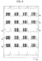
- Fig. 8 is a schematic diagram showing a modeled area using a combination of geometric constructs and modeling methods in accordance with an exemplary embodiment of the present invention.
- Fig. 8 shows a portion of a production area 200 modeled using the geometric units and methods of exemplary embodiments of the present invention in connection with an analytic system 20.
- the modeled production area 200 is generated in one exemplary embodiment using complex embedding of the individual units (or arrays of the individual units) in a large three-dimensional region representing the entire production area.
- the rectangular units 210 are modeled pellet boats into which a triangular lattice of pellets has been embedded using the first geometric units 50 and 50' and the virtual fill methods. Further, each of the rectangular units 210 are the same unit and have been embedded as arrays into the modeled production area 200 using complex embedding. For example, note the interference patterns shown in the pellet boats, which indicate that the contents are created using VFO methods (i.e., created using virtual fill).
- the circular units 220 are modeled three gallon cans that include a triangular lattice of pellets embedded using the first geometric units 50 and 50' and the VFO methods.
- the contents of the three gallon containers may be, for example, grinder swarf, and the fuel mixture could then be modeled using one of the VFO methods with one of the geometric units 50, 70 or 80.
- the availability of different geometry constructs permits modeling of similar equipment that my have entirely different contents.
- containers of fuel pellets must be treated differently from containers with grinder swarf, primarily because of the dimensions of the individual pellets and the particles constituting the grinder swarf.
- Fuel pellets have dimension greater than, for example, 0.30 inches, and modeling of lattices in a geometry such as a three gallon container may only required a few thousand individual pellets. This may be achievable with the complex embedded option.
- Grinder swarf on the other hand, has dimensions much less than 0.01 inches so that modeling in a three gallon container may require millions of individual units. It should be noted that this can not be practically handled with the complex embedded option, but is readily handled with the virtual fill option (VFO) analytic method.
- VFO virtual fill option
- the two rectangular units 230a and 230b are modeled pellet carts, each of which may be the same.
- the rectangular unit 230b has been embedded using a ninety-degree rotation in its specification.
- the pellet carts modeled by the rectangular units 230a and 230b are nestings of embedded regions, for example: a first region representing a two foot long fuel rod (i.e., row of pellets modeled as a rod), is embedded as a two high triangular lattice array into a second region representing a pellet tray into which are also embedded side rails, a tray support and a tray base, all of which are embedded as a fifteen high array in a third region representing a pellet cart.
- the rectangular unit 240 is a modeled layer of pellet trays modeled the same as the two rectangular units 230a and 230b.
- Fig. 9 is a schematic diagram illustrative of the modeled contents within a storage cabinet in the modeled area of Fig. 8.
- Fig. 10 is a schematic diagram illustrative of a close-up view of the modeled tray within the storage cabinet in the modeled area of Fig. 8.
- an array of rod storage cabinets within the production area may be modeled, which may be, for example, multilevel arrays, such as complex embedded arrays embedded into complex embedded arrays embedded into complex embedded arrays.
- Fig. 9 shows the modeled contents 250 (e.g., plurality of trays 260) within each of the storage cabinets and
- Fig. 10 shows an expanded view of a single rod tray 260 (e.g., stainless steel tray) in the cabinet.
- the contents 250 of a single cabinet may not be uniform, for example, as shown, ten of the tray locations 262 are empty, which is required because of criticality safety considerations.
- an entire array may be filled with a given embedded unit, and then one or more of the array locations overwritten with a new unit.
- modeled rods 270 (e.g., fuel rods) in the rod tray 260 are a single clad fuel rod with cladding and air gap as specified in a predefined fuel design. This rod is embedded in the rod tray 260 using complex embedding of an array. If the geometry specifications do not exactly match the internal dimensions of the rod tray 260, the overlapping rods 270 are modeled only in the parts internal to the rod tray 260 boundary.
- Fig. 5 is a schematic diagram illustrating the use of a geometric constructs using in an ordered array in accordance with an exemplary embodiment of the present invention.
- the rods 270 in the rod tray 260 may be modeled as a triangular lattice, using multiple complex regions with a regular fuel rod box region or with a ⁇ 1 (missing edges) using the first geometric units 50 and 50' and as shown in Figure 5.
- a production area containing multiple fissile processes or equipment described herein can be represented in accurate detail by combining the various embodiments described herein (e.g., simple geometric constructs coupled with the CEO and VFO analytic options) to create a complex interaction model.
- analysis of a fissile shipping container for heterogeneous contents may be provided based upon modeling using the various geometric units 50, 70 and 80 and methods described herein.
- heterogeneous contents means that the fissile material, for example enriched UO 2 may occur as clumps of higher density particles rather than being uniformly dispersed through a region (e.g., as in homogeneous powder).
- an exemplary shipping container for shipping large quantities of low enriched UO 2 may include nine internal stainless steel cylindrical canisters that are equally spaced in a three-by-three array in a large outer stainless steel box (e.g., nearly cubical box). Each of the canisters is allowed to contain a specified maximum amount of uranium oxide of unrestricted particle size (e.g., 46 kgs heterogeneous UO 2 per canister at specified maximum U-235 enrichment).
- Nuclear criticality safety evaluation of shipping containers are required by regulations.
- the contents in each of the canisters are modeled as water moderated lattices of full density UO 2 rods, with varying rod diameters, rod heights and rod spacing (pitch) to determine the most reactive configuration. Multiple cases are analyzed based upon the specified rod diameter and pitch and on a varying maximum UO 2 mass in the canisters.
- the height of the rod lattice in the canister is determined by the specified rod diameter and pitch, the UO2 mass limit, with the type of boundary condition specified, for example, whether the rods in the lattices are permitted to overlap the canister boundary or whether individual rods overlapping the boundary are to be deleted in their entirety.
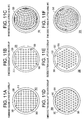
- Figs. 11A-11F illustrate X,Y plots of a single canister modeled using various embodiments of the present invention.
- a plurality of UO 2 fuel rods 300 are modeled surrounded by full density water 310 within a canister 320.
- the canister 320 is modeled within packaging material 330 embedded within the shipping container box.
- the complex embedded option (CEO) is used to provide the modeling.
- the canister is embedded as a single unit in a three-by-three lattice in the X-Y plane, with nine different single unit/lattices embedded in the Z vertical plane.
- each of the geometries shown is modeled by embedding one or more lattices of individual fuel rods into the interior of the canister.
- a two dimensional array of a fuel rod box was embedded within a single complex unit (i.e., embedded square lattice).
- the triangular lattices shown therein may be modeled using the first geometric units 50 and 50' having alternation units with a +1 Missing edges and the other with a -1 axis.
- Figs. 11C and 11F show geometry plots of models using virtual filling as described herein to provide embedded square and triangular lattices, respectively, for the same rod and pitch geometries as shown in Figs. 11A, 11B, 11D and 11E.
- VFO virtual fill option
- the modeled canister is created with only a single embedded box (i.e., single embedded unit).
- the square lattice as shown in Fig. 11C is modeled as an embedded box with a simple fuel cylinder centered in a (X, Y) square
- the triangular lattice as shown in Fig. 11F is modeled as an embedded first geometric unit 50.
- VFO plots of the internal fuel lattice region shown in Figs. 11C and 11F do not show the location of fuel and moderator, but instead show an interference pattern (e.g., curved grid surfaces) as a result of the neutron tracking performed in the virtual fill region.
- an interference pattern e.g., curved grid surfaces
- models of smaller components for example small fuel rods (e.g., 0.025 inches) within a canister may be provided using complex embedding and virtual fill, along with the geometric units as described herein.
- a complex fissile shipping container containing heterogeneous (fissile) material payload described herein can be represented in accurate detail by combining the various embodiments described herein (e.g., simple geometric constructs coupled with the CEO and VFO analytic options) to create a complex shipping container model.
Landscapes
- Engineering & Computer Science (AREA)
- Physics & Mathematics (AREA)
- Theoretical Computer Science (AREA)
- General Engineering & Computer Science (AREA)
- High Energy & Nuclear Physics (AREA)
- Computer Hardware Design (AREA)
- Evolutionary Computation (AREA)
- Geometry (AREA)
- General Physics & Mathematics (AREA)
- Plasma & Fusion (AREA)
- Management, Administration, Business Operations System, And Electronic Commerce (AREA)
- Monitoring And Testing Of Nuclear Reactors (AREA)
- Measurement Of Radiation (AREA)
Applications Claiming Priority (2)
| Application Number | Priority Date | Filing Date | Title |
|---|---|---|---|
| US679427 | 2003-10-07 | ||
| US10/679,427 US7650265B2 (en) | 2003-10-07 | 2003-10-07 | Methods of using geometric constructs for neutronics modeling |
Publications (2)
| Publication Number | Publication Date |
|---|---|
| EP1522936A2 true EP1522936A2 (fr) | 2005-04-13 |
| EP1522936A3 EP1522936A3 (fr) | 2010-09-29 |
Family
ID=34314087
Family Applications (1)
| Application Number | Title | Priority Date | Filing Date |
|---|---|---|---|
| EP04256175A Ceased EP1522936A3 (fr) | 2003-10-07 | 2004-10-06 | Constructions géométriques et méthodes associées de modelisation Monte-Carlo |
Country Status (4)
| Country | Link |
|---|---|
| US (1) | US7650265B2 (fr) |
| EP (1) | EP1522936A3 (fr) |
| JP (1) | JP5436738B2 (fr) |
| KR (1) | KR100946820B1 (fr) |
Families Citing this family (5)
| Publication number | Priority date | Publication date | Assignee | Title |
|---|---|---|---|---|
| US7394472B2 (en) * | 2004-10-08 | 2008-07-01 | Battelle Memorial Institute | Combinatorial evaluation of systems including decomposition of a system representation into fundamental cycles |
| JP5052985B2 (ja) * | 2007-07-31 | 2012-10-17 | 住友重機械工業株式会社 | 分子シミュレーション方法、分子シミュレーション装置、分子シミュレーションプログラム、及び該プログラムを記録した記録媒体 |
| US10838087B2 (en) * | 2018-12-20 | 2020-11-17 | Westinghouse Electric Company Llc | Method and apparatus for real-time measurement of fissile content within chemical and material handling processes |
| CN114239226B (zh) * | 2021-11-23 | 2025-06-13 | 中国核电工程有限公司 | 一种简化管道设备室整体临界安全分析方法 |
| JP2024050250A (ja) * | 2022-09-29 | 2024-04-10 | 三菱重工業株式会社 | 放射性物質の臨界管理方法および装置 |
Family Cites Families (24)
| Publication number | Priority date | Publication date | Assignee | Title |
|---|---|---|---|---|
| US3663346A (en) * | 1970-07-22 | 1972-05-16 | Nasa | Honeycomb core structures of minimal surface tubule sections |
| USH744H (en) * | 1987-11-20 | 1990-02-06 | The United States Of America As Represented By The Department Of Energy | Porcelain enamel neutron absorbing material |
| JPH0540809A (ja) | 1991-08-06 | 1993-02-19 | Canon Inc | 3次元形状モデル作成装置 |
| JPH0644346A (ja) | 1992-07-24 | 1994-02-18 | Canon Inc | 距離画像処理方法及び装置 |
| EP0526881B1 (fr) * | 1991-08-06 | 2002-02-06 | Canon Kabushiki Kaisha | Méthode et appareil de traitement de modèle tri-dimensionel |
| JPH0635996A (ja) | 1992-07-15 | 1994-02-10 | Canon Inc | 3次元形状モデル作成方法及びその装置 |
| JPH0644363A (ja) | 1992-07-24 | 1994-02-18 | Canon Inc | 距離画像処理方法及び装置 |
| GB2295701B (en) * | 1994-11-29 | 1997-06-25 | Honda Motor Co Ltd | Method for machining a product die |
| JP2936088B2 (ja) | 1994-11-29 | 1999-08-23 | 本田技研工業株式会社 | 金型加工用形状データ作成方法 |
| JP2936089B2 (ja) | 1994-11-29 | 1999-08-23 | 本田技研工業株式会社 | 金型加工用形状データ作成方法 |
| JP2980820B2 (ja) | 1994-11-29 | 1999-11-22 | 本田技研工業株式会社 | 金型加工用形状データ作成方法 |
| JPH08153125A (ja) * | 1994-11-29 | 1996-06-11 | Honda Motor Co Ltd | 形状データ作成方法 |
| JP2967030B2 (ja) | 1994-11-29 | 1999-10-25 | 本田技研工業株式会社 | 金型加工用形状データ作成方法 |
| US5936626A (en) * | 1996-02-07 | 1999-08-10 | Silicon Graphics, Inc. | Computer graphics silhouette load management |
| US7110888B1 (en) * | 1998-02-26 | 2006-09-19 | Openeye Scientific Software, Inc. | Method for determining a shape space for a set of molecules using minimal metric distances |
| US6718291B1 (en) * | 1999-07-02 | 2004-04-06 | Vadim Shapiro | Mesh-free method and system for modeling and analysis |
| US7728848B2 (en) * | 2000-03-28 | 2010-06-01 | DG FastChannel, Inc. | Tools for 3D mesh and texture manipulation |
| LU90570B1 (en) * | 2000-04-26 | 2001-10-29 | Europ Economic Community | Method of incineration of minor actinides in nuclear reactors |
| KR20020058608A (ko) * | 2000-12-30 | 2002-07-12 | 오길록 | 컴퓨팅 장치에서 두 개의 비-스플라인 곡선이나 곡면의경계가 연속성을 갖도록 하기 위한 대수적 블렌딩 처리방법 |
| KR100454070B1 (ko) * | 2001-01-31 | 2004-10-20 | 학교법인 중앙대학교 | 컴퓨터를 이용한 그림자를 포함한 실시간 툰 렌더링 방법 |
| WO2002097735A1 (fr) * | 2001-05-31 | 2002-12-05 | Kent Ridge Digital Labs | Systeme et procede de modelisation anatomique |
| JP3845685B2 (ja) | 2001-07-10 | 2006-11-15 | 独立行政法人 日本原子力研究開発機構 | 放射性廃棄物固体内の核分裂性物質量の非破壊的測定装置 |
| JP2003030253A (ja) | 2001-07-17 | 2003-01-31 | Toyota Motor Corp | 3次元形状モデル変形方法 |
| US7233888B2 (en) | 2002-07-09 | 2007-06-19 | General Electric Company | Monte Carlo criticality-mode systems and methods for computing neutron and gamma fluence in a nuclear reactor |
-
2003
- 2003-10-07 US US10/679,427 patent/US7650265B2/en not_active Expired - Fee Related
-
2004
- 2004-10-06 EP EP04256175A patent/EP1522936A3/fr not_active Ceased
- 2004-10-06 JP JP2004293836A patent/JP5436738B2/ja not_active Expired - Lifetime
- 2004-10-07 KR KR1020040079836A patent/KR100946820B1/ko not_active Expired - Fee Related
Non-Patent Citations (1)
| Title |
|---|
| None * |
Also Published As
| Publication number | Publication date |
|---|---|
| US7650265B2 (en) | 2010-01-19 |
| US20050075848A1 (en) | 2005-04-07 |
| JP5436738B2 (ja) | 2014-03-05 |
| KR20050033845A (ko) | 2005-04-13 |
| JP2005114733A (ja) | 2005-04-28 |
| EP1522936A3 (fr) | 2010-09-29 |
| KR100946820B1 (ko) | 2010-03-09 |
Similar Documents
| Publication | Publication Date | Title |
|---|---|---|
| Leppänen | Serpent–a continuous-energy Monte Carlo reactor physics burnup calculation code | |
| Murata et al. | New sampling method in continuous energy Monte Carlo calculation for pebble bed reactors | |
| Rintala et al. | Modeling of realistic pebble bed reactor geometries using the Serpent Monte Carlo code | |
| Whitesides et al. | KENO: A Multigroup Monte Carlo Criticality Program | |
| US7650265B2 (en) | Methods of using geometric constructs for neutronics modeling | |
| Larmier | Stochastic particle transport in disordered media: beyond the Boltzmann equation | |
| Schmalzl et al. | Mixing properties of three‐dimensional (3‐D) stationary convection | |
| Raza et al. | Automated modelling approach for neutronic analysis of high temperature gas-cooled pebble bed reactors | |
| Newton | The development of modern design and reference core neutronics methods for PBMR | |
| Jones et al. | Neutron multiplication and reactor kinetics parameters in stochastic media based on randomized noise functions | |
| Dickinson et al. | The Monte Carlo method for array criticality calculations | |
| Karriem et al. | MCNP Modelling of HTGR Pebble-Type Fuel | |
| Hassanain | Investigation of 16O+ 12C refractive elastic scattering using the-cluster model potential | |
| Talamo | Analytical calculation of the average Dancoff factor for prismatic high-temperature reactors | |
| Nomura et al. | Benchmark calculations by the nuclear criticality safety analysis code system JACS (MGCL, KENO-IV) | |
| Kloosterman et al. | Spatial effects in dancoff factor calculations for pebble-bed HTRs | |
| Donovan et al. | HTGR unit fuel pebble k-infinity results using chord length sampling | |
| Busch | KENO Va Primer: A Primer for Criticality Calculations with SCALE/KENO Va Using CSPAN for Input | |
| Busch et al. | KENO Va Primer: A Primer for Criticality Calculations with SCALE/KENO Va Using GeeWiz | |
| EP4379744A1 (fr) | Gestion de structures pour emballage | |
| Parks et al. | Computational Methods for Criticality Safety Analysis Within the SCALE System | |
| McGraw | Resolution Requirements for Accurate Reactor Calculations Using the Linear Discontinuous Finite Element Method | |
| McKenzie et al. | Nuclear Criticality Safety Fundamentals [PowerPoint] | |
| Teng et al. | A Random Geometry Model in Criticality Calculations of Solutions Containing Raschig Rings | |
| Kuznetsov | Convexification and Global Optimization of Problems Involving the Euclidean Norm |
Legal Events
| Date | Code | Title | Description |
|---|---|---|---|
| PUAI | Public reference made under article 153(3) epc to a published international application that has entered the european phase |
Free format text: ORIGINAL CODE: 0009012 |
|
| AK | Designated contracting states |
Kind code of ref document: A2 Designated state(s): AT BE BG CH CY CZ DE DK EE ES FI FR GB GR HU IE IT LI LU MC NL PL PT RO SE SI SK TR |
|
| AX | Request for extension of the european patent |
Extension state: AL HR LT LV MK |
|
| PUAL | Search report despatched |
Free format text: ORIGINAL CODE: 0009013 |
|
| AK | Designated contracting states |
Kind code of ref document: A3 Designated state(s): AT BE BG CH CY CZ DE DK EE ES FI FR GB GR HU IE IT LI LU MC NL PL PT RO SE SI SK TR |
|
| AX | Request for extension of the european patent |
Extension state: AL HR LT LV MK |
|
| RIC1 | Information provided on ipc code assigned before grant |
Ipc: G21C 19/40 20060101ALI20100826BHEP Ipc: G06F 17/50 20060101AFI20041230BHEP |
|
| 17P | Request for examination filed |
Effective date: 20110329 |
|
| AKX | Designation fees paid |
Designated state(s): DE FR GB SE |
|
| 17Q | First examination report despatched |
Effective date: 20160506 |
|
| RIC1 | Information provided on ipc code assigned before grant |
Ipc: G21C 19/40 20060101ALI20100826BHEP Ipc: G06F 17/50 20060101AFI20041230BHEP |
|
| STAA | Information on the status of an ep patent application or granted ep patent |
Free format text: STATUS: THE APPLICATION HAS BEEN REFUSED |
|
| 18R | Application refused |
Effective date: 20181105 |