EP1522836A2 - Leak detection apparatus for a liquid circulation cooling system - Google Patents
Leak detection apparatus for a liquid circulation cooling system Download PDFInfo
- Publication number
- EP1522836A2 EP1522836A2 EP04077668A EP04077668A EP1522836A2 EP 1522836 A2 EP1522836 A2 EP 1522836A2 EP 04077668 A EP04077668 A EP 04077668A EP 04077668 A EP04077668 A EP 04077668A EP 1522836 A2 EP1522836 A2 EP 1522836A2
- Authority
- EP
- European Patent Office
- Prior art keywords
- wicking material
- coolant
- electrodes
- detection apparatus
- leak detection
- Prior art date
- Legal status (The legal status is an assumption and is not a legal conclusion. Google has not performed a legal analysis and makes no representation as to the accuracy of the status listed.)
- Withdrawn
Links
Images


Classifications
-
- G—PHYSICS
- G01—MEASURING; TESTING
- G01M—TESTING STATIC OR DYNAMIC BALANCE OF MACHINES OR STRUCTURES; TESTING OF STRUCTURES OR APPARATUS, NOT OTHERWISE PROVIDED FOR
- G01M3/00—Investigating fluid-tightness of structures
- G01M3/02—Investigating fluid-tightness of structures by using fluid or vacuum
- G01M3/04—Investigating fluid-tightness of structures by using fluid or vacuum by detecting the presence of fluid at the leakage point
- G01M3/16—Investigating fluid-tightness of structures by using fluid or vacuum by detecting the presence of fluid at the leakage point using electric detection means
- G01M3/18—Investigating fluid-tightness of structures by using fluid or vacuum by detecting the presence of fluid at the leakage point using electric detection means for pipes, cables or tubes; for pipe joints or seals; for valves; for welds; for containers, e.g. radiators
- G01M3/186—Investigating fluid-tightness of structures by using fluid or vacuum by detecting the presence of fluid at the leakage point using electric detection means for pipes, cables or tubes; for pipe joints or seals; for valves; for welds; for containers, e.g. radiators for containers, e.g. radiators
- G01M3/188—Investigating fluid-tightness of structures by using fluid or vacuum by detecting the presence of fluid at the leakage point using electric detection means for pipes, cables or tubes; for pipe joints or seals; for valves; for welds; for containers, e.g. radiators for containers, e.g. radiators for radiators
-
- G—PHYSICS
- G01—MEASURING; TESTING
- G01M—TESTING STATIC OR DYNAMIC BALANCE OF MACHINES OR STRUCTURES; TESTING OF STRUCTURES OR APPARATUS, NOT OTHERWISE PROVIDED FOR
- G01M3/00—Investigating fluid-tightness of structures
- G01M3/02—Investigating fluid-tightness of structures by using fluid or vacuum
- G01M3/04—Investigating fluid-tightness of structures by using fluid or vacuum by detecting the presence of fluid at the leakage point
- G01M3/042—Investigating fluid-tightness of structures by using fluid or vacuum by detecting the presence of fluid at the leakage point by using materials which expand, contract, disintegrate, or decompose in contact with a fluid
- G01M3/045—Investigating fluid-tightness of structures by using fluid or vacuum by detecting the presence of fluid at the leakage point by using materials which expand, contract, disintegrate, or decompose in contact with a fluid with electrical detection means
Definitions
- the present invention is directed to liquid circulation cooling systems for electronic devices and the like, and more particularly to apparatus for detecting, locating and isolating coolant leaks at the pipe joints of such systems.
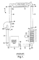
- FIG. 1 depicts a liquid cooling system 10 for one or more heat producing electronic devices 12.
- the device 12 is typically mounted on a circuit board 14, and its upper surface is secured to a cold plate 16 of cooling system 10 by thermal paste, thermal interface material or other means so that heat generated by the device 12 is conducted to the cold plate 16.
- the cold plate 16 is provided with inlet and outlet pipes 16a, 16b through which a liquid coolant such as water or a water-glycol solution is circulated.
- the coolant is stored in a tank or reservoir 18, and a pump 20 draws coolant out of tank 18 for delivery to the cold plate inlet pipe 16a.
- Heated fluid exiting cold plate 16 through outlet pipe 16b is supplied to a heat exchanger 22 before being returned to the tank 18.
- a cooling fan 24 driven by electric motor 26 forces ambient air through the heat exchanger 22, so that the heat transferred from device 12 to the fluid in cold plate 16 is subsequently transferred from the fluid in heat exchanger 22 to circumambient air.
- the potential for fluid leaks is a significant concern, particularly in electronic systems where the leaked fluid can damage various electronic devices and potentially create a risk of electrocution or fire.
- the most likely sources of leakage in the system 10 are the pipe joints.
- the inlet 16a, 18a, 20a, 22a of each device 16, 18, 20, 22 is coupled to the outlet 16b, 18b, 20b, 22b of another device by a connecting pipe 28, 30, 32, 34, and there is a pipe joint at each such coupling.
- the connecting pipes 28, 30, 32, 34 have an inside diameter that matches the outside diameter of the inlet or outlet pipe to which it is coupled, and a clamp 36 prevents the pipes from becoming uncoupled.
- Other possible coupling configurations are depicted in Figures 2-4, described herein.
- the coupled pipes can be soldered or otherwise sealed to prevent fluid leakage, the possibility of fluid leakage remains due to sealing defects or imperfections that occur over time.
- the detection device typically takes the form of a pair of electrodes separated by an absorbent material that is insulative in the absence of fluid but which dissolves or becomes conductive in the presence of fluid.
- a circuit responsive to the resistance between the electrodes activates the alarm when a change in resistance indicative of fluid leakage is detected. See, for example, the U.S. Patent Nos. 4,922,232; 4,974,739; 5,172,730; 5,176,025; and 5,918,267 which pertain to leak detection in pipelines, and the U.S. Patent Nos. 4,870,477 and 5,086,829, which pertain to leak detection for liquid circulation cooling systems.
- the present invention is directed to an improved leak detection apparatus that is particularly suited to liquid circulation cooling systems having pipe joints, including detection devices that envelope the various pipe joints of the cooling system.
- the detection devices comprise a pair of conductors separated by a wicking material impregnated with a crystalline salt that provides a low resistance electrical path between the conductors in the presence of a leak.
- the detection devices comprise a pair of dissimilar metal mesh electrodes separated by an electrolyte-impregnated wicking material to form a water-activated battery that energizes an alarm in the presence of a leak.
- Both embodiments optionally are encased with a water-activated sealing material that hardens in the presence of a leak to contain the leakage.
- FIGS. 2 and 3 are particularly applicable to cooling system pipe joints of the abutment type in which two similarly sized pipes 40 and 42 separated by a small gap 43 are joined by an internal sleeve 44 having an outside diameter equal to or slightly larger than the inside diameter of the pipes 40 and 42.
- the sleeve 44 or the pipes 40, 42 may be coated with a sealing material that is compressed between the sleeve 44 and the pipes 40, 42 to prevent leakage of fluid circulated therethrough.
- the reference numeral 50 designates a leak detection and containment apparatus where the electrodes are defined by the radially spaced metal screens 52 and 54.
- the screens 52 and 54 may be formed of copper or aluminum for example, and are coupled to an external circuit such as depicted in Figure 6 by the external conductors 56 and 58, respectively.
- the screens 52 and 54 are separated from the pipes 40, 42 and from each other by intervening layers of a wicking material 60 that absorbs coolant that may ooze from the pipe joint and acts to soak up and hold the oozing coolant until the joint can be repaired.
- the wicking material 60 which may be formed of felt for example, is preferably impregnated with a crystalline salt such as sodium-bicarbonate or sodium-chloride.
- the wicking material 60 When dry, the wicking material 60 is insulative in nature to establish a high-resistance electrical path between the screens 52 and 54; when moistened by leaking coolant at the pipe joint, the crystalline salt dissolves, forming a highly ionic low-resistance electrical path between the screens 52 and 54. In systems where the coolant itself is highly conductive, impregnation of the wicking material with crystalline salt can be omitted.
- the wicking material 60 can additionally be impregnated with a dry dye material such as cobalt chloride that is dissolved by leaking coolant; in such event, the dye produces a visible stain on the detection apparatus 50, allowing a user to visually identify the location of a detected leak.
- the screens 52, 54 and wicking material 60 are enveloped by a superincumbent layer of sealing material 62 designed to harden and seal the leak on contact with the coolant.
- the sealing material may be a water-activated material such as hydrophobic polyurethane foam or resin, epoxy resin, sodium-polyacrylate gel, or simple plaster-of-paris.
- the apparatus 50 is preferably manufactured in the form of a rectangular strip that is wrapped around some or all of the pipe joints of the cooling system 10, particularly those joints located in proximity to sensitive electronic devices or other electrical equipment where a leak would cause damage and/or pose an electrical hazard.
- the reference numeral 70 designates a leak detection and containment apparatus where the electrodes are defined by the axially spaced metal bands 72 and 74.
- the bands 72 and 74 may be formed of copper or aluminum for example, and are coupled to an external circuit such as depicted in Figure 6 by the external conductors 76 and 78, respectively.
- a sleeve of wicking material 80 surrounds the pipes 40, 42 in the vicinity of the gap 43, and the bands 72 and 74 are secured to opposite axial ends of the wicking material 80 as shown.
- the wicking material 80 separates the bands 72 and 74 from the pipes 40, 42 and from each other; and additionally in this embodiment, the bands 72, 74 serve as clamps to hold the wicking material 80 in place.
- the wicking material 80 may be formed of felt for example, and is impregnated with a dry dye material and crystalline salt to facilitate both visual and electrical detection of coolant leakage.
- the bands 72, 74 and wicking material 80 are optionally enveloped by a superincumbent layer of sealing material 82 designed to harden and seal the leak on contact with the coolant.
- the reference numeral 90 designates a leak detection and containment apparatus essentially as shown in Figure 3, but as applied to a barb-type pipe joint between different sized pipes 92 and 94.
- a sleeve of wicking material 96 surrounds the pipes 92, 94 in the vicinity of the pipe joint, and metal bands 98 and 100 are secured to opposite axial ends of the wicking material 96.
- Conductors 102 and 104 connect the bands 98 and 100 to an external circuit such as depicted in Figure 6.
- the bands 92, 94 and wicking material 96 are optionally enveloped by a superincumbent layer of sealing material 106 designed to harden and seal the leak on contact with the coolant.
- the reference numeral 110 generally designates a patch-type version of the above-described pipe joint leak detection devices that is particularly adapted for detecting leaks from a flat surface in the liquid cooling loop of cold plate 16.
- a sheet of metal foil tape 112 has a rectangular central opening 112a covered by a sheet of wicking material 114 that is somewhat larger than the opening 112a so that the margins of the wicking material 114 adhere to the foil tape 112.
- First and second conductor bars 116, 118 are adhered to foil tape 112 oppositely about the wicking material 114, so that the electrical resistance between conductor bars 116 and 118 is determined by the combined resistance of the intervening wicking material 114 and the marginal portions 112b, 112c of the foil tape 112. As the wicking material 114 moistens due to a coolant leak, the combined electrical resistance decreases, and a circuit such as depicted in Figure 6 coupled to the conductor bars 116, 118 via wires 120, 122 detects the resistance drop as an indication of coolant leakage.
- the wicking material 114 may be impregnated with dry dye and crystalline salts to facilitate visual and electrical leak detection, and the apparatus may be optionally enveloped by a superincumbent layer of sealing material 124 designed to harden and seal the leak on contact with the coolant.
- Figure 6 depicts a leak detection circuit designed to interface with the above-described leak detection devices, designated in Figure 6 by the detector 140.
- a power source such as battery 142 is coupled to a relay coil 144 via a Darlington transistor pair 146 comprising the individual transistors 148 and 150.
- the relay coil 144 is energized to activate a set of contacts 156 that in turn activate an alarm to alert the operator that a coolant leak has been detected.
- the resistor 154 and leak detector 140 couple the base of transistor 148 to the positive terminal of battery 142, while the pull-down resistor 152 couples the base of transistor 148 to the negative terminal of battery 142.
- the normal resistance of detector 140 is relatively high so that the pull-down resistor 152 biases the Darlington pair 146 non-conductive. In the event of a coolant leak, however, the resistance of detector 140 drops precipitously, biasing the Darlington pair 146 conductive to activate the alarm.
- the circuit elements 144-154 may be replicated to provide a detection circuit for each leak detector present in a system 10.
- Figures 7A-7B and 8A-8B depict leak detection devices having an integral coolant-activated battery that interfaces directly to an alarm device, thereby eliminating the need for remote resistance detection circuitry and batteries that must be periodically replaced.
- Figures 7A-7B depict a detection apparatus 160 in the form of an elongated strip that is intended to be wrapped around a pipe joint as depicted in Figure 7B.
- an alarm 178 (such as a piezo-electric sounder) coupled to the apparatus 160 via the wires 174 and 176 sounds to alert the operator or user of the coolant leakage.
- the apparatus 160 comprises first and second electrode strips 162 and 164 separated by a strip of wicking material 166, and upper and lower strips of porous fabric 168, 170 covering the electrode strips 162, 164.
- the porous fabric layers 168, 170 serve to protect the respective electrode strips 162, 164, and also to insulate the electrode strips 162, 164 from pipe 172, and from each other if the wrapping results in any overlap.
- the electrode strips 162, 164 are formed of a screen or mesh material so that leaked coolant soaks into the wicking material 166, and the wicking material is impregnated with crystalline electrolyte that is non-conductive in its dry state.
- one of the electrode strips 162, 164 is formed of aluminum, while the other is formed of copper, so that an aluminum-copper cell is activated in the event of coolant leakage to produce an output voltage of approximately 1.2 volts across lines 174, 176.
- the current produced by the cell is proportional to the active area of the electrodes 162, 164, which increases as leaked coolant soaks into the wicking material 166.
- Other electrode combinations such as copper and magnesium are also possible.
- FIGs 8A-8B depict a detection apparatus 180 comprising first and second blocks 182 and 184 that are clamped together about a butt-joint of two equal diameter pipes 186, 188.
- each of the blocks 182, 184 comprises a stack of plates that form one or more coolant activated battery cells.
- the exterior periphery of the stack is covered by an insulative layer 190, and each stack has a semi-cylindrical recess that is complementary to the exterior periphery of the pipes 186, 188.
- a porous insulative layer is also applied to the pipes 186, 188 in the event that the pipes 186,188 are conductive.
- Each battery cell includes an aluminum plate 192, a layer of wicking material 194 and a copper plate 196 in succession, and each cell is separated by an insulator plate 198.
- the various aluminum plates 192 are electrically coupled by internal inter-connects, as are the various copper plates 196.
- a pair of conductors 200, 202 couple the battery cells of blocks 182 and 184 in parallel, and the wires 204, 206 couple the battery cells to the alarm 208, which may be a piezoelectric sounder as mentioned above.
- the wicking material 194 is impregnated with crystalline electrolyte that is dissolved by leaked coolant to activate the battery cells.
- the present invention provides a reliable and cost-effective means of quickly detecting and locating leaked coolant in a liquid-circulated cooling system 10. While the invention has been described in reference to the illustrated embodiments, it will be understood that various modifications in addition to those mentioned herein will occur to those skilled in the art. For example, the size and shape of the detection apparatus may be varied to suit a given application, materials other than those mentioned herein may be used, and so forth. Additionally, it is possible to apply two or more staged detection devices to a single location; in such a mechanization, initial coolant leakage is detected by a first detection device, and leakage detection by the second and subsequent detection devices indicates the extent of the leak.
- the alarm circuitry may be effective to perform auto-shutdown or other functions in response to detection of a coolant leak.
- the leak detection apparatus may be applied as extensively in a system as desired, and need not be confined solely to the pipe joints.
Landscapes
- Physics & Mathematics (AREA)
- General Physics & Mathematics (AREA)
- Examining Or Testing Airtightness (AREA)
Abstract
Description
Claims (16)
- Leak detection apparatus for a liquid cooling system (10) having coolant pipes (172, 186, 188) and at least one pipe joint , comprising:a wicking material (166, 194) applied to an exterior periphery of said pipe;an electrical detector including first and second spaced electrodes (162, 164, 192, 196) formed of different metals and disposed on said wicking material (166, 194);a crystalline electrolyte activating agent impregnated into said wicking material (166, 194) that is operative when leaked coolant soaks into said wicking material (166, 194) for forming a coolant activated battery that produces an electrical voltage and current flow between said first and second electrodes (162, 164, 192, 196)when coolant leaks into said wicking material 166, 194); andcircuitry (146) coupled to said electrical detector for indicating the presence of a coolant leak when said electrical voltage and current flow are produced.
- The leak detection apparatus of Claim 1, further comprising:a superincumbent layer of material (62, 8, 106, etc) surrounding said electrical detector and wicking material that is operative on contact with said leaked coolant for hardening to form a seal that contains said leaked coolant.
- The leak detection apparatus of Claim 2, wherein said coolant is water, and said superincumbent layer is hydrophobic polyurethane.
- The leak detection apparatus of Claim 1, further comprising:a dye material impregnated into said wicking material (166, 194) that is operative when leaked coolant soaks into said wicking material for dying said wicking material to provide a visual indicator of the leaked coolant.
- The leak detection apparatus of Claim 1, wherein:said first and second electrodes (162, 164) are radially spaced about said pipe (172); anda portion of said wicking material (166) is disposed between said first and second electrodes (162, 164).
- The leak detection apparatus of Claim 5, wherein at least one of said first and second electrodes (162, 164) is a screen that allows said leaked coolant to soak into said portion of wicking material (166) disposed between said first and second electrodes.
- Leak detection apparatus for a liquid cooling system having coolant pipes (40, 42, 92, 94, etc.) and at least one pipe joint (43), comprising:a wicking material (60, 80, 96) applied to an exterior periphery of said pipe;an electrical detector (140) including first and second spaced electrodes (52, 54, 72, 74, 98, 100) disposed on said wicking material (60, 80, 96), said first and second electrodes (52, 54, 72, 74, 98, 100)being oppositely disposed about said pipe joint (43);an activating agent impregnated into said wicking material (60, 80, 96) that is operative when leaked coolant soaks into said wicking material for altering an electrical parameter of said electrical detector; andcircuitry (142-156)coupled to said electrical detector (140) for indicating the presence of a coolant leak in response to said altering of said electrical parameter.
- The leak detection apparatus of Claim 7, wherein:said first and second electrodes (52, 54, 72, 74, 98, 100)clamp said wicking material (60, 80, 96) around said coolant pipes.
- Leak detection apparatus for a liquid cooling system having coolant pipes (186, 188)and at least one pipe joint, comprising:a wicking material (194)applied to an exterior periphery of said pipe (186, 188);an electrical detector including first and second spaced electrodes (192, 196)disposed on said wicking material (194), said first and second electrodes (192, 196) being in the form of plates oriented substantially perpendicular to a longitudinal axis of said coolant pipe (186, 188), with a portion of said wicking material (194) being disposed between said first and second electrodes;an activating agent impregnated into said wicking material that is operative when leaked coolant soaks into said wicking material for altering an electrical parameter of said electrical detector; andcircuitry (208)coupled to said electrical detector for indicating the presence of a coolant leak in response to said altering of said electrical parameter.
- The leak detection apparatus of Claim 9, wherein said first and second electrodes (192, 196) are formed of different metals, said activating agent is a crystalline electrolyte, and said altered electrical parameter is an electrical voltage and current flow between said first and second electrodes.
- The leak detection apparatus of Claim 10, wherein said electrical detector includes third and fourth electrodes formed of different metals, and electrically coupled to said first and second electrodes (192, 196), respectively, to form a multi-cell coolant activated battery.
- The leak detection apparatus of Claim 9, wherein said first and second electrodes (192, 196) and said wicking material (194) have a semi-cylindrical periphery that seats on said coolant pipes(186, 188).
- The leak detection apparatus of Claim 12, wherein said electrical detector includes third and fourth plate electrodes and intervening wicking material (184) having a semi-cylindrical periphery that seats on said coolant pipes (186, 188) in opposition to said first and second electrodes (192, 196).
- The leak detection apparatus of Claim 13, wherein said first and second electrodes (192, 196) are electrically coupled (200, 202) to said third and fourth electrodes, respectively, to form a multi-cell coolant activated battery.
- Leak detection apparatus for a liquid cooling system (10), comprising:a metal foil member (112) having a central opening (112a), and adhesively secured to a component of said system (10);an electrical detector (140) including first and second spaced electrodes (116, 118) disposed on said foil member (112) oppositely about said central opening (112a);a sheet of wicking material (114) spanning the central opening (112a) of said foil member (112), and having marginal portions supported by said foil member;an activating agent impregnated into said wicking material (114) that is operative when leaked coolant at said component soaks into said wicking material (114) for altering an electrical parameter of said electrical detector;a superincumbent layer of material (124)surrounding said electrical detector and wicking material that is operative on contact with said leaked coolant for hardening to form a seal that contains said leaked coolant; andmeans (142-156) coupled to said electrical detector (140) for indicating the presence of a coolant leak in response to said altering of said electrical parameter.
- The leak detection apparatus of Claim 15, wherein said superincumbent layer of material (124) is hydrophobic polyurethane.
Applications Claiming Priority (2)
| Application Number | Priority Date | Filing Date | Title |
|---|---|---|---|
| US10/684,069 US6826948B1 (en) | 2003-10-09 | 2003-10-09 | Leak detection apparatus for a liquid circulation cooling system |
| US684069 | 2003-10-09 |
Publications (2)
| Publication Number | Publication Date |
|---|---|
| EP1522836A2 true EP1522836A2 (en) | 2005-04-13 |
| EP1522836A3 EP1522836A3 (en) | 2006-06-07 |
Family
ID=33477232
Family Applications (1)
| Application Number | Title | Priority Date | Filing Date |
|---|---|---|---|
| EP04077668A Withdrawn EP1522836A3 (en) | 2003-10-09 | 2004-09-28 | Leak detection apparatus for a liquid circulation cooling system |
Country Status (2)
| Country | Link |
|---|---|
| US (2) | US6826948B1 (en) |
| EP (1) | EP1522836A3 (en) |
Cited By (4)
| Publication number | Priority date | Publication date | Assignee | Title |
|---|---|---|---|---|
| GB2410561B (en) * | 2004-01-27 | 2007-08-01 | David John Roughley | Water leak detector |
| DE102012013474A1 (en) * | 2012-07-09 | 2014-01-09 | Fresenius Medical Care Deutschland Gmbh | Device for detecting moisture for a device for monitoring access to a patient |
| US20160069475A1 (en) * | 2013-03-08 | 2016-03-10 | Georg Fischer Rohrleitungssysteme Ag | Valve having a leakage indicator |
| DE102018006950A1 (en) * | 2018-09-03 | 2020-03-05 | Ewald Dörken Ag | Humidity sensor |
Families Citing this family (143)
| Publication number | Priority date | Publication date | Assignee | Title |
|---|---|---|---|---|
| DE10150075A1 (en) * | 2001-10-10 | 2003-04-17 | Roxtec Ingenieur Gmbh | Module for a sealed passage for cables/pipes, through constructions, has a lateral recess around its outer sealing surfaces with at least one drilling to the interior to test the hermetic sealing |
| US6826948B1 (en) * | 2003-10-09 | 2004-12-07 | Delphi Technologies, Inc. | Leak detection apparatus for a liquid circulation cooling system |
| US7623028B2 (en) | 2004-05-27 | 2009-11-24 | Lawrence Kates | System and method for high-sensitivity sensor |
| US7218237B2 (en) | 2004-05-27 | 2007-05-15 | Lawrence Kates | Method and apparatus for detecting water leaks |
| US7142107B2 (en) | 2004-05-27 | 2006-11-28 | Lawrence Kates | Wireless sensor unit |
| US7561057B2 (en) * | 2004-05-27 | 2009-07-14 | Lawrence Kates | Method and apparatus for detecting severity of water leaks |
| NO325700B1 (en) * | 2004-09-09 | 2008-07-07 | Schneider Gmbh & Co Kg Franz | toboggan |
| US7228726B2 (en) | 2004-09-23 | 2007-06-12 | Lawrence Kates | System and method for utility metering and leak detection |
| US7454955B2 (en) * | 2004-10-29 | 2008-11-25 | Hewlett-Packard Development Company, L.P. | Leak detection structure |
| US9456915B2 (en) | 2004-11-19 | 2016-10-04 | Fulfilium, Inc. | Methods, devices, and systems for obesity treatment |
| US8070807B2 (en) | 2004-11-19 | 2011-12-06 | Fulfillium, Inc. | Wireless breach detection |
| WO2007005947A1 (en) | 2005-07-01 | 2007-01-11 | Terahop Networks, Inc. | Nondeterministic and deterministic network routing |
| US20070051166A1 (en) * | 2005-09-02 | 2007-03-08 | Baker Kenneth R | Leak detection systems and methods |
| US7281390B2 (en) | 2005-09-09 | 2007-10-16 | Delphi Technologies, Inc. | Self-powered evaporative cooler |
| WO2007033180A1 (en) * | 2005-09-12 | 2007-03-22 | Abela Pharmaceuticals, Inc. | Materials for facilitating administration of dimethyl sulfoxide (dmso) and related compounds |
| US8480797B2 (en) | 2005-09-12 | 2013-07-09 | Abela Pharmaceuticals, Inc. | Activated carbon systems for facilitating use of dimethyl sulfoxide (DMSO) by removal of same, related compounds, or associated odors |
| WO2007033083A2 (en) | 2005-09-12 | 2007-03-22 | Abela Pharmaceuticals, Inc. | Systems for removing dimethyl sulfoxide (dmso) or related compounds, or odors associated with same |
| EP2324838A1 (en) | 2005-09-12 | 2011-05-25 | Abela Pharmaceuticals, Inc. | Compositions Comprising Dimethyl Sulfoxide (DMSO) |
| US7528711B2 (en) | 2005-12-19 | 2009-05-05 | Lawrence Kates | Portable monitoring unit |
| US20070193285A1 (en) * | 2006-02-21 | 2007-08-23 | Knight Paul A | Testing for Leaks in a Two-Phase Liquid Cooling System |
| US8366316B2 (en) * | 2006-04-14 | 2013-02-05 | Deka Products Limited Partnership | Sensor apparatus systems, devices and methods |
| CA2648803C (en) | 2006-04-14 | 2017-06-20 | Deka Products Limited Partnership | Systems, devices and methods for fluid pumping, heat exchange, thermal sensing, and conductivity sensing |
| US7967022B2 (en) | 2007-02-27 | 2011-06-28 | Deka Products Limited Partnership | Cassette system integrated apparatus |
| US10537671B2 (en) | 2006-04-14 | 2020-01-21 | Deka Products Limited Partnership | Automated control mechanisms in a hemodialysis apparatus |
| US7716966B2 (en) * | 2006-06-28 | 2010-05-18 | Medtronic Cryocath Lp | Mesh leak detection system for a medical device |
| KR101911864B1 (en) | 2007-02-27 | 2018-10-26 | 데카 프로덕츠 리미티드 파트너쉽 | Hemodialysis system |
| US20090107335A1 (en) | 2007-02-27 | 2009-04-30 | Deka Products Limited Partnership | Air trap for a medical infusion device |
| US8562834B2 (en) | 2007-02-27 | 2013-10-22 | Deka Products Limited Partnership | Modular assembly for a portable hemodialysis system |
| US8409441B2 (en) | 2007-02-27 | 2013-04-02 | Deka Products Limited Partnership | Blood treatment systems and methods |
| US8491184B2 (en) | 2007-02-27 | 2013-07-23 | Deka Products Limited Partnership | Sensor apparatus systems, devices and methods |
| US8393690B2 (en) | 2007-02-27 | 2013-03-12 | Deka Products Limited Partnership | Enclosure for a portable hemodialysis system |
| US8357298B2 (en) | 2007-02-27 | 2013-01-22 | Deka Products Limited Partnership | Hemodialysis systems and methods |
| US9028691B2 (en) | 2007-02-27 | 2015-05-12 | Deka Products Limited Partnership | Blood circuit assembly for a hemodialysis system |
| US8042563B2 (en) | 2007-02-27 | 2011-10-25 | Deka Products Limited Partnership | Cassette system integrated apparatus |
| US8425471B2 (en) | 2007-02-27 | 2013-04-23 | Deka Products Limited Partnership | Reagent supply for a hemodialysis system |
| US8771508B2 (en) | 2008-08-27 | 2014-07-08 | Deka Products Limited Partnership | Dialyzer cartridge mounting arrangement for a hemodialysis system |
| US8079412B2 (en) * | 2008-03-03 | 2011-12-20 | Satellite Systems & Solutions, Inc. | Method and apparatus for mitigating environmental impact due to fluid leaks |
| WO2009140669A2 (en) | 2008-05-16 | 2009-11-19 | Terahop Networks, Inc. | Securing, monitoring and tracking shipping containers |
| US8486552B2 (en) * | 2008-06-30 | 2013-07-16 | Lg Chem, Ltd. | Battery module having cooling manifold with ported screws and method for cooling the battery module |
| US9759495B2 (en) * | 2008-06-30 | 2017-09-12 | Lg Chem, Ltd. | Battery cell assembly having heat exchanger with serpentine flow path |
| US20110138886A1 (en) * | 2008-07-04 | 2011-06-16 | Carrier Corporation | Refrigerated Transport System Testing |
| JP5239569B2 (en) * | 2008-07-10 | 2013-07-17 | 株式会社リコー | Image forming apparatus |
| US7631666B1 (en) * | 2008-08-04 | 2009-12-15 | Kwan Yuen Abraham Ng | Reinforced flexible hose with leakage indicator and method of making same |
| BRPI0921494A2 (en) | 2008-11-03 | 2018-10-30 | Prad Reasearch And Development Ltd | method of planning a underground forming sampling operation, method of controlling a underground forming sampling operation, method of controlling a drilling operation for an underground formation, and method of sampling during the drilling operation. |
| US20100127460A1 (en) * | 2008-11-26 | 2010-05-27 | Odyssian Technology, Llc | Seals with integrated leak detection capability |
| US20100275619A1 (en) * | 2009-04-30 | 2010-11-04 | Lg Chem, Ltd. | Cooling system for a battery system and a method for cooling the battery system |
| US8403030B2 (en) * | 2009-04-30 | 2013-03-26 | Lg Chem, Ltd. | Cooling manifold |
| US8663829B2 (en) * | 2009-04-30 | 2014-03-04 | Lg Chem, Ltd. | Battery systems, battery modules, and method for cooling a battery module |
| US8061211B1 (en) | 2009-06-19 | 2011-11-22 | Odyssian Technology, Llc | Seal with integrated sensor |
| US8399118B2 (en) * | 2009-07-29 | 2013-03-19 | Lg Chem, Ltd. | Battery module and method for cooling the battery module |
| US8399119B2 (en) * | 2009-08-28 | 2013-03-19 | Lg Chem, Ltd. | Battery module and method for cooling the battery module |
| EP3072545B1 (en) | 2009-10-30 | 2019-05-08 | DEKA Products Limited Partnership | Apparatus for detecting disconnection of an intravascular access device |
| US9839609B2 (en) | 2009-10-30 | 2017-12-12 | Abela Pharmaceuticals, Inc. | Dimethyl sulfoxide (DMSO) and methylsulfonylmethane (MSM) formulations to treat osteoarthritis |
| BR112012013276A2 (en) * | 2009-12-01 | 2019-09-24 | Stuart David | rupture detection system, device for detecting discontinuity in a breast implant, method for detecting discontinuity in a breast implant breast |
| US8289173B2 (en) * | 2010-02-22 | 2012-10-16 | King Fahd University Of Petroleum And Minerals | Leak detection band |
| US20110227721A1 (en) * | 2010-03-22 | 2011-09-22 | Khaled Mezghani | Leak detection system for pipes |
| US8662153B2 (en) | 2010-10-04 | 2014-03-04 | Lg Chem, Ltd. | Battery cell assembly, heat exchanger, and method for manufacturing the heat exchanger |
| CA2837200C (en) | 2011-05-24 | 2020-07-07 | Deka Products Limited Partnership | Hemodialysis system |
| AU2012259459B2 (en) | 2011-05-24 | 2016-06-02 | Deka Products Limited Partnership | Blood treatment systems and methods |
| JP5517265B2 (en) * | 2011-09-20 | 2014-06-11 | 富士フイルム株式会社 | Sealing sheet, liquid discharge head using the same, and inkjet apparatus |
| US8869599B2 (en) | 2012-01-23 | 2014-10-28 | Massachusetts Institute Of Technology | Leak detection system based on force transduction |
| DK2812640T3 (en) | 2012-02-10 | 2018-11-26 | Carrier Corp | PROCEDURE FOR DETECTING LOSS OF REFRIGERANT |
| US9379420B2 (en) | 2012-03-29 | 2016-06-28 | Lg Chem, Ltd. | Battery system and method for cooling the battery system |
| US9605914B2 (en) | 2012-03-29 | 2017-03-28 | Lg Chem, Ltd. | Battery system and method of assembling the battery system |
| US9105950B2 (en) | 2012-03-29 | 2015-08-11 | Lg Chem, Ltd. | Battery system having an evaporative cooling member with a plate portion and a method for cooling the battery system |
| US8852781B2 (en) | 2012-05-19 | 2014-10-07 | Lg Chem, Ltd. | Battery cell assembly and method for manufacturing a cooling fin for the battery cell assembly |
| US20130333447A1 (en) * | 2012-06-15 | 2013-12-19 | Thomas Arthur White | Leakage detection |
| US9306199B2 (en) | 2012-08-16 | 2016-04-05 | Lg Chem, Ltd. | Battery module and method for assembling the battery module |
| US9083066B2 (en) | 2012-11-27 | 2015-07-14 | Lg Chem, Ltd. | Battery system and method for cooling a battery cell assembly |
| US9261311B2 (en) * | 2012-12-27 | 2016-02-16 | Teradyne, Inc. | Test system having liquid containment chambers over connectors |
| US20140190568A1 (en) * | 2013-01-08 | 2014-07-10 | GM Global Technology Operations LLC | Coolant Activated Rechargeable Energy Storage System Drain Plug |
| US9068900B2 (en) | 2013-01-08 | 2015-06-30 | GM Global Technology Operations LLC | Deflection sensitive coolant activated drain plug detection system for high voltage battery packs |
| US8852783B2 (en) | 2013-02-13 | 2014-10-07 | Lg Chem, Ltd. | Battery cell assembly and method for manufacturing the battery cell assembly |
| US20140251583A1 (en) * | 2013-03-07 | 2014-09-11 | Asetek A/S | Leak detection system for a liquid cooling system |
| US9647292B2 (en) | 2013-04-12 | 2017-05-09 | Lg Chem, Ltd. | Battery cell assembly and method for manufacturing a cooling fin for the battery cell assembly |
| US9293792B2 (en) | 2013-05-10 | 2016-03-22 | Tesla Motors, Inc. | Self-activated draining system |
| US9184424B2 (en) | 2013-07-08 | 2015-11-10 | Lg Chem, Ltd. | Battery assembly |
| US9257732B2 (en) | 2013-10-22 | 2016-02-09 | Lg Chem, Ltd. | Battery cell assembly |
| US9444124B2 (en) | 2014-01-23 | 2016-09-13 | Lg Chem, Ltd. | Battery cell assembly and method for coupling a cooling fin to first and second cooling manifolds |
| GB2524738A (en) | 2014-03-31 | 2015-10-07 | Eaton Ind Ip Gmbh & Co Kg | Sealing sleeve with leakage detection |
| US10173904B2 (en) | 2014-04-10 | 2019-01-08 | Haier Us Appliance Solutions, Inc. | System for detecting a liquid and a water filter assembly |
| US10173905B2 (en) | 2014-04-10 | 2019-01-08 | Haier Us Appliance Solutions, Inc. | System for detecting a liquid and a water filter assembly |
| US10173155B2 (en) | 2014-04-10 | 2019-01-08 | Haier Us Appliance Solutions, Inc. | Water filter assembly and a system for detecting liquid |
| US20150290674A1 (en) | 2014-04-10 | 2015-10-15 | General Electric Company | Method for treating foam |
| US10770762B2 (en) | 2014-05-09 | 2020-09-08 | Lg Chem, Ltd. | Battery module and method of assembling the battery module |
| US10084218B2 (en) | 2014-05-09 | 2018-09-25 | Lg Chem, Ltd. | Battery pack and method of assembling the battery pack |
| US10502477B2 (en) | 2014-07-28 | 2019-12-10 | Haier Us Appliance Solutions, Inc. | Refrigerator appliance |
| US9484559B2 (en) | 2014-10-10 | 2016-11-01 | Lg Chem, Ltd. | Battery cell assembly |
| US9412980B2 (en) | 2014-10-17 | 2016-08-09 | Lg Chem, Ltd. | Battery cell assembly |
| US10512195B2 (en) | 2014-10-31 | 2019-12-17 | Hewlett Packard Enterprise Development Lp | Server device with capacitive circuit |
| US9786894B2 (en) | 2014-11-03 | 2017-10-10 | Lg Chem, Ltd. | Battery pack |
| DE102014223170A1 (en) * | 2014-11-13 | 2016-05-19 | Contitech Schlauch Gmbh | delivery hose |
| US9627724B2 (en) | 2014-12-04 | 2017-04-18 | Lg Chem, Ltd. | Battery pack having a cooling plate assembly |
| WO2016121952A1 (en) * | 2015-01-29 | 2016-08-04 | アラム株式会社 | Liquid sensor |
| KR101673346B1 (en) * | 2015-03-18 | 2016-11-07 | 현대자동차 주식회사 | Inspection apparatus of electrolyte membrane |
| US20150268125A1 (en) * | 2015-06-04 | 2015-09-24 | Caterpillar Inc. | Oil detection sensor module for sensing oil leakage in coolant system |
| US9983171B2 (en) | 2015-07-28 | 2018-05-29 | Ppg Industries Ohio, Inc. | Aerospace transparency having moisture sensors |
| US9975646B2 (en) * | 2015-07-28 | 2018-05-22 | Ppg Industries Ohio, Inc. | Aerospace transparency having moisture sensors |
| CN105072874A (en) * | 2015-08-18 | 2015-11-18 | 曙光信息产业(北京)有限公司 | Cooling method and device for server |
| US10018407B2 (en) | 2015-08-25 | 2018-07-10 | Haier Us Appliance Solutions, Inc. | Filter cartridge |
| US10150067B2 (en) | 2015-09-08 | 2018-12-11 | Haier Us Appliance Solutions, Inc. | Filter cartridge |
| US10391430B2 (en) | 2015-09-21 | 2019-08-27 | Haier Us Appliance Solutions, Inc. | Filter assembly |
| CA3007129C (en) * | 2015-12-04 | 2024-02-27 | Instrumar Limited | Apparatus and method of detecting breaches in pipelines |
| US10206312B2 (en) * | 2015-12-21 | 2019-02-12 | Dell Products, L.P. | Liquid cooled rack information handling system having storage drive carrier for leak containment and vibration mitigation |
| US10078031B2 (en) | 2016-02-16 | 2018-09-18 | Massachusetts Institute Of Technology | Compliant leak detection system |
| BR112019007592A2 (en) | 2016-10-17 | 2019-07-02 | Univ King Fahd Pet & Minerals | pipe leak detection systems, devices and methods |
| US10571179B2 (en) | 2017-01-26 | 2020-02-25 | Haier Us Appliance Solutions, Inc. | Refrigerator appliance with a clear icemaker |
| US10605493B2 (en) | 2017-01-26 | 2020-03-31 | Haier Us Appliance Solutions, Inc. | Refrigerator appliance with a clear icemaker |
| US10274237B2 (en) | 2017-01-31 | 2019-04-30 | Haier Us Appliance Solutions, Inc. | Ice maker for an appliance |
| CN106876811B (en) * | 2017-04-12 | 2024-02-09 | 华霆(合肥)动力技术有限公司 | Leakage detecting device and battery module leakage detecting system |
| US10040009B1 (en) | 2017-06-27 | 2018-08-07 | Haier Us Appliance Solutions, Inc. | Filter cartridge |
| US10466201B2 (en) | 2018-02-01 | 2019-11-05 | FPG Industries Ohio, Inc. | Complex impedance moisture sensor and sensing method |
| TWI725422B (en) * | 2018-05-31 | 2021-04-21 | 技嘉科技股份有限公司 | Liquid cooling device, coolant circulation system , and liquid leaking detection method |
| CN110941314B (en) * | 2018-05-31 | 2022-04-19 | 技嘉科技股份有限公司 | Liquid-cooled heat conduction device, liquid-cooled circulation system, and liquid leakage detection method |
| US11274778B2 (en) | 2018-12-12 | 2022-03-15 | International Business Machines Corporation | Couplings with engagement monitor |
| TWI826627B (en) * | 2018-12-31 | 2023-12-21 | 美商聖高拜塑膠製品公司 | Leak detection systems and fluid conduit comprising the same |
| CN109709614B (en) * | 2019-02-25 | 2020-09-04 | 安徽瑞迪工程科技有限公司 | Method for accurately measuring geomembrane permeation holes of refuse landfill by three poles |
| GB2582371B (en) * | 2019-03-22 | 2023-07-26 | W E Rawson Ltd | Improvements relating to the sealing of pipe liners |
| US11346741B2 (en) * | 2019-05-29 | 2022-05-31 | Dell Products L.P. | Detecting leaks in liquid-cooled information handling systems with moisture wicking material |
| JP7079226B2 (en) * | 2019-07-12 | 2022-06-01 | ダイキン工業株式会社 | Refrigerant cycle system equipped with a refrigerant leak notification device and a refrigerant leakage notification device |
| CN110568911B (en) * | 2019-09-05 | 2021-04-23 | 英业达科技有限公司 | Server |
| WO2021064566A1 (en) * | 2019-10-03 | 2021-04-08 | 3M Innovative Properties Company | Capacitive touch sensor-based leak detector film |
| DE102020000907A1 (en) | 2020-02-13 | 2021-08-19 | Daimler Ag | Detection of a leak in a cooling circuit |
| US11441968B2 (en) * | 2020-02-28 | 2022-09-13 | Rolls-Royce North American Technologies Inc. | System and method for detecting leaks in a sealed coolant system |
| FR3109443A1 (en) * | 2020-04-16 | 2021-10-22 | Psa Automobiles Sa | FLUID LEAK DETECTION SYSTEM |
| US11788918B2 (en) | 2020-06-18 | 2023-10-17 | Trevillyan Labs, Llc | Fluid detection fabric |
| DE102020120682A1 (en) * | 2020-08-05 | 2022-02-10 | Innome Gmbh | sealing part |
| WO2022170505A1 (en) * | 2021-02-09 | 2022-08-18 | Siemens Aktiengesellschaft | Sensor strip, chain-type sensor strip, and flange leak detection method |
| WO2022170506A1 (en) * | 2021-02-09 | 2022-08-18 | Siemens Aktiengesellschaft | Sensor strip and flange leak detection method |
| US12216025B2 (en) * | 2021-03-08 | 2025-02-04 | Baidu Usa Llc | Advanced sealing structure for liquid cooling |
| US20220291072A1 (en) * | 2021-03-10 | 2022-09-15 | Dell Products, Lp | Optical liquid coolant leak detector |
| US11960335B2 (en) * | 2021-03-26 | 2024-04-16 | Baidu Usa Llc | Leak detection and prevention system |
| CN113799349B (en) * | 2021-10-21 | 2023-11-17 | 昆山市嘉华精密模具有限公司 | Cooling system for leakage early warning type injection mold |
| CN116066762B (en) | 2021-11-03 | 2025-12-09 | 台达电子工业股份有限公司 | Leakage detection sensor and leakage detection system suitable for same |
| TWI806215B (en) * | 2021-11-03 | 2023-06-21 | 台達電子工業股份有限公司 | Leak detection sensor and leak detection system using same |
| US12504344B2 (en) * | 2022-07-14 | 2025-12-23 | Dell Products L.P. | Liquid cooling leak sensor |
| CN115493762B (en) * | 2022-08-24 | 2024-10-29 | 苏州浪潮智能科技有限公司 | Liquid leakage detection method, circuit, device, computer equipment and storage medium |
| CN116202036B (en) * | 2023-03-20 | 2023-12-22 | 盐城市崇达石化机械有限公司 | Throttle manifold for preventing drainage of petroleum well |
| KR102547740B1 (en) * | 2023-03-21 | 2023-06-26 | 주식회사 사이몬 | Sensor integrated leak detection clamp and leak detection device using it |
| KR102568177B1 (en) * | 2023-06-19 | 2023-08-18 | 주식회사 사이몬 | Sensor integrated leak detection electric fitting socket and leak detection device using it |
| CN117117355B (en) * | 2023-10-23 | 2024-02-09 | 宁德时代新能源科技股份有限公司 | Liquid leakage detection device and battery |
| EP4604269A1 (en) * | 2024-02-15 | 2025-08-20 | Volvo Truck Corporation | A cooling system for a battery pack |
| CN118687217B (en) * | 2024-08-06 | 2024-12-10 | 南京泽喜机电有限公司 | Refrigeration effect fault detection equipment for central air conditioner based on recovery |
Family Cites Families (26)
| Publication number | Priority date | Publication date | Assignee | Title |
|---|---|---|---|---|
| US3485085A (en) * | 1968-04-23 | 1969-12-23 | William M Hawkins Jr | Leak detector |
| US3721970A (en) * | 1971-10-06 | 1973-03-20 | Atomic Energy Commission | Alkali metal leak detector |
| US4041771A (en) * | 1975-05-09 | 1977-08-16 | Arthur D. Little, Inc. | Temperature-sensitive detector |
| JPS5612530A (en) * | 1979-07-12 | 1981-02-06 | Hitachi Ltd | Detecting system for sodium leakage |
| US4446892A (en) * | 1979-09-05 | 1984-05-08 | Maxwell Ag | Method and apparatus for monitoring lengths of hose |
| US4589275A (en) * | 1982-04-16 | 1986-05-20 | The Kendall Company | Pipe coating |
| GB8307382D0 (en) * | 1983-03-17 | 1983-04-27 | Maxwell A J | Battery-sensor |
| US4864847A (en) * | 1985-05-29 | 1989-09-12 | The United States Of America As Represented By The Administrator Of The National Aeronautics And Space Administration | Fluid leak indicator |
| JPH0797617B2 (en) | 1986-05-23 | 1995-10-18 | 株式会社日立製作所 | Refrigerant leakage prevention device |
| US4918977A (en) * | 1986-09-30 | 1990-04-24 | Tatsuta Electric Wire And Cable Co., Ltd. | Liquid leakage detector line |
| US4974739A (en) | 1988-07-15 | 1990-12-04 | Ozite Corporation | Storage tank and method of making a storage tank |
| JPH0227560U (en) * | 1988-08-11 | 1990-02-22 | ||
| US4926129A (en) * | 1988-10-12 | 1990-05-15 | Raychem Corporation | Sensor assembly for detecting multiple events and distinguishing between them |
| US4922232A (en) | 1988-10-21 | 1990-05-01 | Bosich Joseph F | Leakage containment and detection systems |
| US5172730A (en) | 1989-07-03 | 1992-12-22 | Insituform Of North American, Inc. | Two-wall leakage detection system for a pipe |
| DE4015075C2 (en) * | 1990-05-10 | 1997-02-27 | Bernd Brandes | Procedure for the determination of leaks in line pipes for liquid media |
| JPH0827109B2 (en) | 1990-07-12 | 1996-03-21 | 甲府日本電気株式会社 | Liquid cooling device |
| US5176025A (en) | 1991-02-19 | 1993-01-05 | E. O. Butts Consultants Ltd. | Pipeline secondary containment system and method |
| US5341128A (en) * | 1992-04-10 | 1994-08-23 | Chomerics, Inc. | Sensor element for detection of hydrocarbons |
| FR2740873B1 (en) * | 1995-11-07 | 1998-01-02 | D Auria Stanislas Boulet | LIQUID PRESENCE DETECTION DEVICE |
| US5918267A (en) | 1997-06-04 | 1999-06-29 | Raychem Corporation | Leak detection |
| CA2213459A1 (en) * | 1997-08-20 | 1999-02-20 | Michael Lee Roberts | Leak monitoring system |
| US6175310B1 (en) * | 1999-05-10 | 2001-01-16 | Richard J. Gott | Leak detection tape |
| US6865941B2 (en) * | 2001-11-21 | 2005-03-15 | Before-The-Event, Ltd. | Liquid leak detector |
| US6550499B1 (en) * | 2002-02-08 | 2003-04-22 | Taiwan Semiconductor Manufacturing Co., Ltd | Detectable liquid leakage conduit |
| US6826948B1 (en) * | 2003-10-09 | 2004-12-07 | Delphi Technologies, Inc. | Leak detection apparatus for a liquid circulation cooling system |
-
2003
- 2003-10-09 US US10/684,069 patent/US6826948B1/en not_active Expired - Fee Related
-
2004
- 2004-09-28 EP EP04077668A patent/EP1522836A3/en not_active Withdrawn
- 2004-12-06 US US11/005,256 patent/US20050092070A1/en not_active Abandoned
Cited By (7)
| Publication number | Priority date | Publication date | Assignee | Title |
|---|---|---|---|---|
| GB2410561B (en) * | 2004-01-27 | 2007-08-01 | David John Roughley | Water leak detector |
| DE102012013474A1 (en) * | 2012-07-09 | 2014-01-09 | Fresenius Medical Care Deutschland Gmbh | Device for detecting moisture for a device for monitoring access to a patient |
| US9731086B2 (en) | 2012-07-09 | 2017-08-15 | Fresenius Medical Care Deutschland Gmbh | Device for detecting moisture for an arrangement for monitoring an access to a patient |
| US10046120B2 (en) | 2012-07-09 | 2018-08-14 | Fresenius Medical Care Deutschland Gmbh | Device for detecting moisture for an arrangement for monitoring an access to a patient |
| US20160069475A1 (en) * | 2013-03-08 | 2016-03-10 | Georg Fischer Rohrleitungssysteme Ag | Valve having a leakage indicator |
| US9677685B2 (en) * | 2013-03-08 | 2017-06-13 | Georg Fischer Rohrleitungssysteme Ag | Valve having a leakage indicator |
| DE102018006950A1 (en) * | 2018-09-03 | 2020-03-05 | Ewald Dörken Ag | Humidity sensor |
Also Published As
| Publication number | Publication date |
|---|---|
| US20050092070A1 (en) | 2005-05-05 |
| EP1522836A3 (en) | 2006-06-07 |
| US6826948B1 (en) | 2004-12-07 |
Similar Documents
| Publication | Publication Date | Title |
|---|---|---|
| US6826948B1 (en) | Leak detection apparatus for a liquid circulation cooling system | |
| TWI725422B (en) | Liquid cooling device, coolant circulation system , and liquid leaking detection method | |
| US7042235B2 (en) | Method for the detection of leaks in components conducting liquids and device for executing the method | |
| CN206161256U (en) | Lithium ion battery package liquid cooling system weeping detection device | |
| WO2000011737A1 (en) | Secondary battery | |
| JP2013203395A (en) | Threshold condition indication in vehicle fuel system | |
| US3868620A (en) | Level sensor and method of making the same | |
| CN110941314B (en) | Liquid-cooled heat conduction device, liquid-cooled circulation system, and liquid leakage detection method | |
| JP4739183B2 (en) | Battery | |
| CA2784178C (en) | Electrode device used in iontophoresis treatment | |
| US5149598A (en) | Battery arrangement | |
| CN110672285B (en) | Liquid leakage detection device | |
| JP6154867B2 (en) | Inspection method and inspection system | |
| CN108458748A (en) | A kind of pipeline performance condition checkout gear | |
| JP2002324572A (en) | Sealed battery insulation inspection apparatus and sealed battery insulation inspection method | |
| CN111578982B (en) | Temperature sensor and method for manufacturing temperature sensor | |
| JPS6212460B2 (en) | ||
| KR101895750B1 (en) | Leaking sensor for target area | |
| JP2022516470A (en) | Leakage detection system and how to detect leaks | |
| JPH03296653A (en) | Water leak sensor | |
| EP3254071B1 (en) | Piezoelectric ultrasonic detector | |
| NO860096L (en) | SENSOR CABLE FOR DETECTION OF THE PRESENCE OF AN ELECTRIC CONDUCTIVE LIQUID. | |
| CN113345770A (en) | Circuit breaker protector and junction box thereof | |
| KR20170075606A (en) | water detection apparatus | |
| JP2020134506A (en) | Temperature sensor and manufacturing method of temperature sensor |
Legal Events
| Date | Code | Title | Description |
|---|---|---|---|
| PUAI | Public reference made under article 153(3) epc to a published international application that has entered the european phase |
Free format text: ORIGINAL CODE: 0009012 |
|
| AK | Designated contracting states |
Kind code of ref document: A2 Designated state(s): AT BE BG CH CY CZ DE DK EE ES FI FR GB GR HU IE IT LI LU MC NL PL PT RO SE SI SK TR |
|
| AX | Request for extension of the european patent |
Extension state: AL HR LT LV MK |
|
| PUAL | Search report despatched |
Free format text: ORIGINAL CODE: 0009013 |
|
| AK | Designated contracting states |
Kind code of ref document: A3 Designated state(s): AT BE BG CH CY CZ DE DK EE ES FI FR GB GR HU IE IT LI LU MC NL PL PT RO SE SI SK TR |
|
| AX | Request for extension of the european patent |
Extension state: AL HR LT LV MK |
|
| RIC1 | Information provided on ipc code assigned before grant |
Ipc: G01M 3/04 20060101ALI20060428BHEP Ipc: G01M 3/16 20060101ALI20060428BHEP Ipc: G01M 3/18 20060101AFI20050118BHEP |
|
| 17P | Request for examination filed |
Effective date: 20061207 |
|
| AKX | Designation fees paid |
Designated state(s): AT BE BG CH CY CZ DE DK EE ES FI FR GB GR HU IE IT LI LU MC NL PL PT RO SE SI SK TR |
|
| 17Q | First examination report despatched |
Effective date: 20090330 |
|
| STAA | Information on the status of an ep patent application or granted ep patent |
Free format text: STATUS: THE APPLICATION IS DEEMED TO BE WITHDRAWN |
|
| 18D | Application deemed to be withdrawn |
Effective date: 20090811 |