EP1522784B1 - Dispositif muni d'un système de sécurité - Google Patents
Dispositif muni d'un système de sécurité Download PDFInfo
- Publication number
- EP1522784B1 EP1522784B1 EP04023955A EP04023955A EP1522784B1 EP 1522784 B1 EP1522784 B1 EP 1522784B1 EP 04023955 A EP04023955 A EP 04023955A EP 04023955 A EP04023955 A EP 04023955A EP 1522784 B1 EP1522784 B1 EP 1522784B1
- Authority
- EP
- European Patent Office
- Prior art keywords
- accordance
- protected zone
- signal
- protection
- operating device
- Prior art date
- Legal status (The legal status is an assumption and is not a legal conclusion. Google has not performed a legal analysis and makes no representation as to the accuracy of the status listed.)
- Expired - Lifetime
Links
Images
Classifications
-
- B—PERFORMING OPERATIONS; TRANSPORTING
- B30—PRESSES
- B30B—PRESSES IN GENERAL
- B30B15/00—Details of, or accessories for, presses; Auxiliary measures in connection with pressing
- B30B15/28—Arrangements for preventing distortion of, or damage to, presses or parts thereof
- B30B15/285—Arrangements for preventing distortion of, or damage to, presses or parts thereof preventing a full press stroke if there is an obstruction in the working area
-
- B—PERFORMING OPERATIONS; TRANSPORTING
- B21—MECHANICAL METAL-WORKING WITHOUT ESSENTIALLY REMOVING MATERIAL; PUNCHING METAL
- B21D—WORKING OR PROCESSING OF SHEET METAL OR METAL TUBES, RODS OR PROFILES WITHOUT ESSENTIALLY REMOVING MATERIAL; PUNCHING METAL
- B21D55/00—Safety devices protecting the machine or the operator, specially adapted for apparatus or machines dealt with in this subclass
-
- F—MECHANICAL ENGINEERING; LIGHTING; HEATING; WEAPONS; BLASTING
- F16—ENGINEERING ELEMENTS AND UNITS; GENERAL MEASURES FOR PRODUCING AND MAINTAINING EFFECTIVE FUNCTIONING OF MACHINES OR INSTALLATIONS; THERMAL INSULATION IN GENERAL
- F16P—SAFETY DEVICES IN GENERAL; SAFETY DEVICES FOR PRESSES
- F16P3/00—Safety devices acting in conjunction with the control or operation of a machine; Control arrangements requiring the simultaneous use of two or more parts of the body
-
- F—MECHANICAL ENGINEERING; LIGHTING; HEATING; WEAPONS; BLASTING
- F16—ENGINEERING ELEMENTS AND UNITS; GENERAL MEASURES FOR PRODUCING AND MAINTAINING EFFECTIVE FUNCTIONING OF MACHINES OR INSTALLATIONS; THERMAL INSULATION IN GENERAL
- F16P—SAFETY DEVICES IN GENERAL; SAFETY DEVICES FOR PRESSES
- F16P3/00—Safety devices acting in conjunction with the control or operation of a machine; Control arrangements requiring the simultaneous use of two or more parts of the body
- F16P3/12—Safety devices acting in conjunction with the control or operation of a machine; Control arrangements requiring the simultaneous use of two or more parts of the body with means, e.g. feelers, which in case of the presence of a body part of a person in or near the danger zone influence the control or operation of the machine
- F16P3/14—Safety devices acting in conjunction with the control or operation of a machine; Control arrangements requiring the simultaneous use of two or more parts of the body with means, e.g. feelers, which in case of the presence of a body part of a person in or near the danger zone influence the control or operation of the machine the means being photocells or other devices sensitive without mechanical contact
- F16P3/144—Safety devices acting in conjunction with the control or operation of a machine; Control arrangements requiring the simultaneous use of two or more parts of the body with means, e.g. feelers, which in case of the presence of a body part of a person in or near the danger zone influence the control or operation of the machine the means being photocells or other devices sensitive without mechanical contact using light grids
Definitions
- the present invention relates to a device, in particular a bending device.
- Bending presses which use a light barrier arrangement for monitoring a protected area. For some processing operations, it is necessary to deactivate one or more photoelectric sensors in order to specifically allow certain interventions in the protected area. This is done according to the prior art, for example by an emergency stop of the device, which is triggered by the intervention finally admitted, and a subsequent, renewed start pulse of the operator to continue the processing operation, during which continuation of the processing operation then defined light barriers are disabled. However, this has the disadvantage that the processing process is interrupted. Alternatively, it is known to provide an additional switch for switching off the light barriers, which is operated before the beginning of the bending operation, which results in that certain light barriers are deactivated for a single, subsequent bending operation. Such a bending press is known for example from DE 197 17 299 A1. However, this has the disadvantage that an additional switch to be actuated provided on the bending press and must be operated by the operator.
- the protected area is changed, preferably reduced, to be.
- the protection area is preferably an area near the movable device part. With the help of the protective device can be monitored whether, for example, an object or a human body part is located in a danger zone of the device.
- a fourth signal can be output via the operating device, by means of which an emergency stop of the device can be triggered.
- the operating device comprises a switch, in particular a foot switch.
- the third signal of the operating device can preferably be triggered by multiple actuation of the operating device.
- the third signal is triggered by a double operation, which operates rapidly one after the other, or by a double actuation of the operating device.
- the third signal of the operating device can be triggered by an additional switch position.
- the additional switch position can be realized in that the switch is temporarily, in particular before the actual machining process, brought into a position which is opposite to the actuating position substantially or this is substantially opposite.
- this additional switch position may accordingly be e.g. be achieved by lifting the footswitch.
- a voice processing device is preferably provided for processing the input data, in particular voice data.
- the solution variant with speech input device is explained in more detail in the description of the figures.
- the protection device of a device according to the invention has a default setting of the protection range, and the device further comprises a reset device for automatically resetting the protection range to the standard setting after each completed machining operation of the device.
- the protection area is reset in each case when switching on or initializing the device in the default setting.
- the means for adjusting the protection area further comprises an additional selection device for selecting the protection area.
- an additional selection device for selecting the protection area.
- it can preferably be signaled by means of the operating device or the voice input device that a protection range should be provided deviating from the standard setting, and by means of the selection device it is possible to select how the protection range should be changed concretely.
- a protection area can be selected from at least two different protection areas deviating from the standard setting.
- the protective device preferably comprises at least one light barrier. More preferably, a light barrier arrangement can be provided with multiple light barriers.
- the protective device for monitoring a volume-shaped protective field with a predetermined protective field extension may have a transmitting device for emitting at least one light beam and a receiving device for detecting the at least one light beam, wherein the protective field extension is variably adjustable. It is preferred if the transmitting device consists of at least one light source, in particular a laser diode, the transmitted light is expanded by a transmitting optics and the receiving device consists of a flat arrangement of individual receivers, in particular a CMOS matrix, wherein at least certain, preferably all individual receiver can be selectively activated and deactivated.
- the protection device further comprises means for stopping the device when an abnormality has been detected in the protection area.
- An abnormality may in particular occur, for example, when an object or a human body part is in the currently active protection area during operation.
- the protective device is preferably arranged on the movable device part and movable with this.
- the protective device can be achieved that the danger zone in the vicinity of the movable device part is continuously monitored. Furthermore, this does not require the entire area in which the movable device part can move with a unnecessarily extensive or large protective device to be monitored.
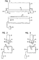
- FIGS. 1 and 2 The device shown is a bending press.
- the device comprises a fixed lower tool 10 and an upper tool 12 movable relative to the lower tool 10.
- the lower tool 10 is movable and the upper tool 12 is stationary or that both tools 10, 12 are movable.
- a workpiece to be machined 50 can be arranged on the lower tool 10.
- a recess 14 is provided into which portions of the workpiece may enter as it is being machined.
- the upper tool 12 which can be moved toward and away from the lower tool 10, comprises a section 16 which is complementary in shape to the recess 14 and which enters the recess 14 during the machining operation and thus deforms the workpiece 50.
- the protective device 18 comprises three light barriers 20, 22, 24 (see also FIG. 2).
- the light barriers 20, 22, 24 are arranged such that they form a protective area which at least partially surrounds the section 16.
- an existing in the movement path of the upper tool 12 human body part, such as a finger or a hand detected and the editing process are interrupted to avoid injury to the operator. If all photocells 20, 22, 24 are activated, this is called the default setting of the photocells.
- the arrangement and number of photocells 20, 22, 24 can be varied as desired depending on the application.
- the protective device 18 is further configured such that the light barriers are deactivated when the upper tool 12 is so close to the workpiece to be machined that a presence of an undesirable object or a human body part in the space between the upper and lower tool can be substantially excluded ,
- the operation of the device by means of a foot pedal 26.
- the foot pedal 26 includes at least three positions in which it can be brought. When the foot pedal 26 is in the first position, this corresponds to an idle state of the device. Further, the operation of the device can be stopped when the foot pedal 26 is brought to the first position. With the help of the second position of the foot pedal 26, a work function or a processing operation of the device can be activated. Preferably, the foot pedal 26 must be held in the second position throughout the machining process. The third position allows a so-called emergency stop or emergency stop. Here, the movement of the device is stopped immediately and blocked the device in the current switching position.
- a further, in this case, fourth position is provided. If that Footpedal 26 is brought into this fourth position, one or more of the light barriers 20, 22, 24 are switched off for a single processing operation in a predefined manner. Thus, a deviating from the default setting, in particular reduced or reduced protection range can be set. A reduction of the protection range is particularly advantageous when a workpiece is to be processed, protrude from the areas during the machining process in the protection area and thus would lead to an unwanted stopping of the device.
- the fourth position is preferably designed such that it is achieved by a movement of the foot pedal 26 in a direction which is substantially opposite to the direction of movement to the second position.
- an additional switch 28 is provided as a selection device on the device, by means of which different combinations of light barriers 20, 22, 24 can be adjusted, which are to be deactivated depending on the application. Depending on what is to be processed for a workpiece, it may be necessary to switch off one or more light barriers 20, 22, 24 in order to enable uninterrupted operation.
- the switch 28 may preferably be brought into at least two positions. As a result, at least two settings deviating from the standard setting of the light barriers can be provided for in particular two mutually different, reduced protection areas.
- the operator places the workpiece 50 on the lower tool 10 and brings the foot pedal 26 from the first to the second position. This starts the editing process.
- the upper tool 12 moves toward the lower tool 10 and comes into contact with the workpiece 50. As a result, the workpiece is deformed, in particular bent.
- the operator first selects by means of the switch 28 how the protected area is to be reduced, ie which of the light barriers 20, 22, 24 is to be switched off. In the present case, the light barrier 20 is turned off.
- the operator brings the foot pedal 26 into the fourth position before the actual machining operation begins.
- the protective device is signaled that, in the present case, the light barrier 20 is to be switched off for the subsequent machining operation.
- the machining operation as described with reference to FIGS. 1 and 2 is performed without unnecessary interruption.
- the protection area is reset to the default setting. This prevents that a reduced protection range is inadvertently used in a subsequent processing operation. For a subsequent processing operation, the reduced protection range would again have to be selected accordingly by selectively actuating the foot pedal 26 in its fourth position and, if appropriate, actuating the switch 28.
- the signaling or confirmation of the changed protection zone can be carried out by bringing the foot pedal 26 into the second position twice in succession before the actual machining operation. The machining operation is then performed as described above.
- the switch 28 can be dispensed with. This will be described below.
- additional foot pedal positions can be provided by means of which the respective protection area to be used can be selected.
- the signaling can be effected by different, multiple actuation of the foot pedal 26.
- the signaling of the changed protection area is effected by means of a voice input device.
- the operator indicates by voice input that the protection area should be reduced. This input is processed by means of a speech recognition device.
- command words and / or command sets are preferably used.
- the voice input preferably takes place via a headset microphone (headset) in order to ensure better recognition performance.
- headset microphone headset
- a switch for selecting the reduced guard area may be provided according to the embodiment described with reference to FIGS. 1 to 3.
- the voice input confirms or signals that the protection range as selected by the switch should be reduced.
- the indication of how the protection range is to be reduced is also signaled by the speech input.
- the foot switch can be completely dispensed with, even if the activation of the machining process is realized by means of voice input.
- the activation of the reduced protection area is effected by means of the foot pedal 26 and the indication as to how the modified protection area should be configured is realized by means of voice input.
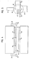
- Figures 4 and 5 relate to an alternative embodiment of the protection device, wherein the means for adjusting the protection area in this embodiment can also be formed as described above in connection with Figures 1 to 3.
- the device shown in Fig. 4 which is formed as a press brake, has an upper tool 12 ', which can be driven to a working movement vertically downwards against a lower tool 10' to bend on the lower tool 10 'resting workpiece 54. During this working movement, an opening gap 30 between the upper tool 12 'and the workpiece 54 is gradually closed.
- a holding arm 32 On the two sides of the upper tool 12 ', a holding arm 32 is provided in each case.
- the holding arms 32 carry a transmitting device 34 and a spatially resolving receiving device 36, which are parts of an optoelectronic sensor.
- the transmitting device 34 has a laser diode with a transmitting optics (not shown in the figures), which transmits the transmitted light of the Expands laser diode to a light beam 38.
- the receiving device 36 has a rectangular CMOS matrix receiver, which is acted upon by the light beam 38.
- the light beam 38 passes through the opening gap 30 below the upper tool 12 '.
- the outline of the activated part of the receiving device 36 thus defines within the light beam 38 a volume-shaped protective field 40 between the upper tool 12 'and the lower tool 10', as will be explained below.
- an evaluation and control device of the sensor (not shown in the figures) detects an interruption of the light beam 38 within the protective field 40, it triggers a switch-off process for stopping the upper tool 12 '.
- an operator who, for example, inserts the workpiece 54 into the opening gap 30, is protected from being injured by the upper tool 12 '.
- Fig. 5 shows the position of the upper tool 11, the light beam 38, the receiving device 36 and the protective field 40.
- a workpiece 54 ' here is a box to be machined on the lower tool 10' stored.
- the box 54 ' would interfere with a protective field that would be present upon activation of all receiving elements of the receiving device 36. Accordingly, according to FIG. 5, only a reduced protective field 40 is used, into which no parts of the box 54 'engage during the bending process, so that there is no interruption of the bending operation.
- Switching between a maximum possible protective field in which all receiving elements of the receiving device 36 are activated and a reduced protective field 40 according to FIG. 5 can take place according to any of the principles of the invention explained above.
Landscapes
- Engineering & Computer Science (AREA)
- General Engineering & Computer Science (AREA)
- Mechanical Engineering (AREA)
- Bending Of Plates, Rods, And Pipes (AREA)
- Presses And Accessory Devices Thereof (AREA)
- Protection Of Pipes Against Damage, Friction, And Corrosion (AREA)
- Electrical Discharge Machining, Electrochemical Machining, And Combined Machining (AREA)
- Crushing And Grinding (AREA)
- Gas-Insulated Switchgears (AREA)
Claims (13)
- Appareil, en particulier appareil de pliage comprenant :- au moins une partie d'appareil mobile (12) ;- un dispositif de manoeuvre (26) pour manoeuvrer l'appareil, le dispositif de manoeuvre (26) pouvant permettre de déclencher au moins un premier signal pour actionner l'appareil et un deuxième signal pour arrêter l'appareil ;- un dispositif de protection (18) pour surveiller une zone de protection de l'appareil ; et- un dispositif d'adaptation sélective d'une zone de protection avant l'actionnement de l'appareil ;caractérisé en ce que le dispositif pour adapter la zone de protection peut être sollicité par un troisième signal du dispositif de manoeuvre (26).
- Appareil selon la revendication 1, caractérisé en ce que le dispositif de manoeuvre (26) comprend un interrupteur (26), en particulier un interrupteur à pédale (26).
- Appareil selon l'une des revendications précédentes, caractérisé en ce que le troisième signal du dispositif de manoeuvre (26) peut être déclenché par actionnement multiple du dispositif de manoeuvre (26).
- Appareil selon la revendication 2, caractérisé en ce que le troisième signal du dispositif de manoeuvre (26) peut être déclenché par une position d'interrupteur additionnelle.
- Appareil, en particulier appareil de pliage comprenant :- au moins une partie d'appareil mobile (12) ;- un dispositif de manoeuvre (26) pour manoeuvrer l'appareil, le dispositif de manoeuvre (26) pouvant permettre de déclencher au moins un premier signal pour actionner l'appareil et un deuxième signal pour arrêter l'appareil ;- un dispositif de protection (18) pour surveiller une zone de protection de l'appareil ; et- un dispositif d'adaptation sélective d'une zone de protection avant l'actionnement de l'appareil ;caractérisé en ce que le dispositif pour adapter la zone de protection comprend un dispositif d'entrée vocale.
- Appareil selon l'une des revendications précédentes, caractérisé en ce que le dispositif de protection (18) présente un réglage standard de la zone de protection et l'appareil comprend en outre un dispositif de réinitialisation pour réinitialiser automatiquement la zone de protection dans le réglage standard après chaque actionnement de l'appareil.
- Appareil selon l'une des revendications précédentes, caractérisé en ce que le dispositif pour adapter la zone de protection comprend en outre un dispositif de sélection (28) additionnel pour sélectionner la zone de protection.
- Appareil selon l'une des revendications précédentes, caractérisé en ce que le dispositif de protection (18) comprend au moins une barrière lumineuse (20, 22, 24).
- Appareil selon l'une des revendications 1 à 7, caractérisé en ce que le dispositif de protection présente, pour surveiller un champ de protection en forme de volume avec extension de champ prédéterminée, un dispositif émetteur (34) pour émettre au moins un rayon lumineux (38) et un dispositif récepteur (36) pour détecter ledit au moins un rayon lumineux (38), l'extension de champ de protection étant réglable de façon variable.
- Appareil selon la revendication 9, caractérisé en ce que le dispositif émetteur (34) est constitué par au moins une source lumineuse, en particulier par une diode laser, dont la lumière émettrice est élargie par un système optique émetteur et en ce que le dispositif récepteur (36) est constitué par un agencement surfacique de récepteurs individuels, en particulier par une matrice CMOS, dans lequel au moins certains récepteurs individuels, de préférence tous les récepteurs individuels, sont activables et désactivables de manière ciblée.
- Appareil selon l'une des revendications précédentes, caractérisé en ce que le dispositif de protection (18) comprend en outre un dispositif pour arrêter l'appareil lorsqu'une anomalie a été détectée dans la zone de protection.
- Appareil selon l'une des revendications précédentes, caractérisé en ce que le dispositif de protection (18) est agencé sur la partie d'appareil mobile (12).
- Utilisation d'un dispositif de protection (18) ainsi qu'un dispositif de manoeuvre (26) selon l'une des revendications précédentes, pour protéger un appareil, en particulier un appareil de pliage.
Applications Claiming Priority (2)
| Application Number | Priority Date | Filing Date | Title |
|---|---|---|---|
| DE10346918 | 2003-10-09 | ||
| DE10346918A DE10346918A1 (de) | 2003-10-09 | 2003-10-09 | Vorrichtung mit Schutzeinrichtung |
Publications (2)
| Publication Number | Publication Date |
|---|---|
| EP1522784A1 EP1522784A1 (fr) | 2005-04-13 |
| EP1522784B1 true EP1522784B1 (fr) | 2007-02-14 |
Family
ID=34306338
Family Applications (1)
| Application Number | Title | Priority Date | Filing Date |
|---|---|---|---|
| EP04023955A Expired - Lifetime EP1522784B1 (fr) | 2003-10-09 | 2004-10-07 | Dispositif muni d'un système de sécurité |
Country Status (7)
| Country | Link |
|---|---|
| US (1) | US7963137B2 (fr) |
| EP (1) | EP1522784B1 (fr) |
| JP (1) | JP4612387B2 (fr) |
| CN (1) | CN1605406A (fr) |
| AT (1) | ATE354055T1 (fr) |
| AU (1) | AU2004218689B2 (fr) |
| DE (2) | DE10346918A1 (fr) |
Families Citing this family (16)
| Publication number | Priority date | Publication date | Assignee | Title |
|---|---|---|---|---|
| DE102005019097A1 (de) * | 2005-04-25 | 2006-11-02 | Sick Ag | Verfahren zur Inbetriebnahme, Justierung, Wartung oder Steuerung einer optoelektronischen Schutzeinrichtung |
| AT510949B1 (de) * | 2010-12-17 | 2015-07-15 | Trumpf Maschinen Austria Gmbh | Steuer- und regelvorrichtung für eine biegepresse |
| EP2573445B1 (fr) * | 2011-09-26 | 2021-05-05 | Fiessler Elektronik GmbH & Co. KG | Manipulateur |
| US20150273633A1 (en) * | 2012-10-26 | 2015-10-01 | Komatsu Industries Corporation | Thermal cutting machine |
| CN103111550B (zh) * | 2013-01-28 | 2015-06-24 | 孙振刚 | 折弯机用安全保护器 |
| CN103507409A (zh) * | 2013-09-19 | 2014-01-15 | 安庆市康明纳包装有限公司 | 制袋机模具安全防护装置 |
| EP2939758B1 (fr) | 2014-04-29 | 2019-01-16 | Schechtl Maschinenbau GmbH | Dispositif de déformation pour la déformation plastique d'un composant comprenant un système de sécurité |
| JP6243954B2 (ja) * | 2016-04-14 | 2017-12-06 | 株式会社アマダホールディングス | プレスブレーキの安全装置 |
| CN106247154A (zh) * | 2016-08-29 | 2016-12-21 | 山东穆柯传感器有限公司 | 一种光电保护装置 |
| AT518993B1 (de) * | 2016-11-18 | 2018-03-15 | Trumpf Maschinen Austria Gmbh & Co Kg | Verfahren zum Betrieb einer Biegemaschine |
| CN106838595B (zh) * | 2017-03-17 | 2023-06-20 | 诺亘(上海)工业自动化有限公司 | 折弯机专用多点安全光幕 |
| CN110456423B (zh) * | 2018-05-07 | 2024-03-19 | 特鲁普机械奥地利有限公司及两合公司 | 用于弯曲单元的切削碎屑识别 |
| AT521528B1 (de) | 2018-07-31 | 2020-04-15 | Trumpf Maschinen Austria Gmbh & Co Kg | Verfahren zum Betreiben einer Biegepresse |
| CN109127948B (zh) * | 2018-11-07 | 2019-11-29 | 济宁科力光电产业有限责任公司 | 一种折弯机用安全保护方法及系统 |
| EP4088833A1 (fr) * | 2021-05-12 | 2022-11-16 | Bystronic Laser AG | Machine à plier, en particulier presse plieuse, dotée d'un système de sécurité |
| EP4527516A1 (fr) * | 2023-09-20 | 2025-03-26 | Fiessler Elektronik GmbH & Co. KG | Machine de pliage et procédé de fonctionnement d'une machine de pliage |
Family Cites Families (16)
| Publication number | Priority date | Publication date | Assignee | Title |
|---|---|---|---|---|
| US4660703A (en) * | 1983-11-07 | 1987-04-28 | Nevio Filcich | Method and apparatus for machine safety |
| JP2712043B2 (ja) * | 1989-04-10 | 1998-02-10 | 株式会社小森安全機研究所 | 工作機の光線式安全装置 |
| US5375063A (en) * | 1991-09-20 | 1994-12-20 | Clemson University | Apparatus and method for voice controlled apparel machine |
| AU667057B2 (en) * | 1991-10-18 | 1996-03-07 | Thomas John Appleyard | Brake press safety apparatus |
| DE19631579A1 (de) * | 1996-08-05 | 1998-02-12 | Vhf Computer Gmbh | Akustische Not-Aus- bzw. Not-Halt-Einrichtung |
| DE19717299C2 (de) * | 1996-08-20 | 2002-03-14 | Fiessler Elektronik Ohg | Schutzeinrichtung für Maschinen,insbesondere für Abkantpressen, Schneidemaschinen oder Stanzmaschinen |
| DE19809709A1 (de) * | 1998-03-06 | 1999-09-09 | Sick Ag | Vorrichtung zum Überwachen eines Schutzbereichs |
| US6660993B2 (en) * | 1999-04-16 | 2003-12-09 | Tirops Safety-Technology Inc. | Safety apparatus and protection method for machines |
| JP3603084B2 (ja) * | 1999-07-02 | 2004-12-15 | 独立行政法人産業安全研究所 | ブランキングシステム |
| DE29920715U1 (de) * | 1999-11-25 | 2000-02-24 | Leuze Lumiflex GmbH & Co., 80993 München | Lichtschrankenanordnung zur Überwachung eines Gefahrenbereiches einer Maschine |
| DE10123562A1 (de) * | 2001-05-15 | 2002-11-21 | Fiessler Elektronik Ohg | Schutzeinrichtung für Maschinen, wie Abkantpressen, Schneidemaschinen, Stanzmaschinen oder dergleichen |
| EP1388128A1 (fr) * | 2001-05-17 | 2004-02-11 | Siemens Aktiengesellschaft | Dispositif et procede pour commander une installation a l'aide d'un tableau de commande et/ou par entree vocale |
| DE10143505B4 (de) * | 2001-09-05 | 2010-07-08 | Sick Ag | Sicherungsverfahren und optoelektronischer Sensor |
| US6980133B2 (en) * | 2002-01-24 | 2005-12-27 | Intel Corporation | Use of two independent pedals for a foot-operated mouse |
| JP2003218679A (ja) * | 2002-01-25 | 2003-07-31 | Keyence Corp | 多光軸光電式安全装置 |
| DE20217426U1 (de) * | 2002-11-05 | 2003-01-16 | Pilz GmbH & Co., 73760 Ostfildern | Sicherheitseinrichtung für eine Maschine, insbesondere für eine Biegepresse |
-
2003
- 2003-10-09 DE DE10346918A patent/DE10346918A1/de not_active Withdrawn
-
2004
- 2004-10-07 AT AT04023955T patent/ATE354055T1/de active
- 2004-10-07 DE DE502004002891T patent/DE502004002891D1/de not_active Expired - Lifetime
- 2004-10-07 EP EP04023955A patent/EP1522784B1/fr not_active Expired - Lifetime
- 2004-10-08 US US10/961,538 patent/US7963137B2/en not_active Expired - Fee Related
- 2004-10-08 AU AU2004218689A patent/AU2004218689B2/en not_active Ceased
- 2004-10-08 JP JP2004295483A patent/JP4612387B2/ja not_active Expired - Fee Related
- 2004-10-09 CN CNA2004100903014A patent/CN1605406A/zh active Pending
Also Published As
| Publication number | Publication date |
|---|---|
| DE10346918A1 (de) | 2005-05-04 |
| EP1522784A1 (fr) | 2005-04-13 |
| US7963137B2 (en) | 2011-06-21 |
| ATE354055T1 (de) | 2007-03-15 |
| AU2004218689B2 (en) | 2009-07-16 |
| AU2004218689A1 (en) | 2005-04-28 |
| JP4612387B2 (ja) | 2011-01-12 |
| US20050076688A1 (en) | 2005-04-14 |
| DE502004002891D1 (de) | 2007-03-29 |
| CN1605406A (zh) | 2005-04-13 |
| JP2005138180A (ja) | 2005-06-02 |
Similar Documents
| Publication | Publication Date | Title |
|---|---|---|
| EP1561066B1 (fr) | Dispositif de securite pour machine, en particulier pour une presse a plier | |
| EP1306603B1 (fr) | Procédé et dispositif de commande d'une fonction relative à la sécurité d'une machine | |
| DE69735472T2 (de) | Optische sicherheitsvorrichtung zum montieren auf einen beweglichen bauteil | |
| EP1522784A1 (fr) | Dispositif muni d'un système de sécurité | |
| EP1589279B1 (fr) | Procédé pour la sécurité d'une machine-outil et capteur optoélectronique pour la mise en oeuvre d'un tel procédé | |
| EP1662195B1 (fr) | Dispositif de sécurité et procédé pour détérminer la course d'inertie d'une machine | |
| EP1387121B1 (fr) | Dispositif de protection pour machines telles que presses-plieuses, découpeuses, machines à estamper ou analogues | |
| EP1200767A1 (fr) | Dispositif de protection pour machines telles que presses-plieuses, decoupeuses, machines a estamper ou analogues | |
| EP3321557B1 (fr) | Dispositif de déformation et procédé de fonctionnement d'un dispositif de déformation | |
| EP1599693B1 (fr) | Procede de securite et detecteur opto-electronique | |
| EP1291573B1 (fr) | Procédé de protection et détecteur optoélectronique | |
| EP3722651B1 (fr) | Dispositif de déformation et procédé de fonctionnement d'un dispositif de déformation | |
| EP3536416B1 (fr) | Procédé de surveillance d'une installation de fabrication ainsi qu'installation de fabrication dotée d'un système de sécurité | |
| EP1515078B1 (fr) | Dispositif de protection pour machines telles que presses-plieuses, découpeuses,machines à estamper ou analogues. | |
| EP1748245B1 (fr) | Dispositif de protection pour machines telles que presses-plieuses, découpeuses, machines à estamper ou analogues | |
| EP2573445B1 (fr) | Manipulateur | |
| EP1687563A1 (fr) | Procede de securisation et dispositif de securite destines a une machine, notamment a une presse a plier | |
| EP1746335B1 (fr) | Procédé pour sécuriser une presse à plier et capteur optoélectronique pour la mise en ouvre d'un tel procédé | |
| EP4527516A1 (fr) | Machine de pliage et procédé de fonctionnement d'une machine de pliage | |
| EP2431650A1 (fr) | Système de protection pour unité de commande sur des machines, notamment des presses de pliage | |
| EP3101330B1 (fr) | Presse de pliage et procédé d'actionnement d'une presse de pliage | |
| DE10246609A1 (de) | Schutzeinrichtung für Maschinen, wie Biegepressen, Schneidemaschinen, Stanzmaschinen oder dergleichen | |
| DE102010011786A1 (de) | Verfahren und Sicherheitsvorrichtung zur Steuerung und Absicherung einer Maschine |
Legal Events
| Date | Code | Title | Description |
|---|---|---|---|
| PUAI | Public reference made under article 153(3) epc to a published international application that has entered the european phase |
Free format text: ORIGINAL CODE: 0009012 |
|
| AK | Designated contracting states |
Kind code of ref document: A1 Designated state(s): AT BE BG CH CY CZ DE DK EE ES FI FR GB GR HU IE IT LI LU MC NL PL PT RO SE SI SK TR |
|
| AX | Request for extension of the european patent |
Extension state: AL HR LT LV MK |
|
| 17P | Request for examination filed |
Effective date: 20050715 |
|
| AKX | Designation fees paid |
Designated state(s): AT BE BG CH CY CZ DE DK EE ES FI FR GB GR HU IE IT LI LU MC NL PL PT RO SE SI SK TR |
|
| GRAP | Despatch of communication of intention to grant a patent |
Free format text: ORIGINAL CODE: EPIDOSNIGR1 |
|
| GRAS | Grant fee paid |
Free format text: ORIGINAL CODE: EPIDOSNIGR3 |
|
| GRAA | (expected) grant |
Free format text: ORIGINAL CODE: 0009210 |
|
| AK | Designated contracting states |
Kind code of ref document: B1 Designated state(s): AT BE BG CH CY CZ DE DK EE ES FI FR GB GR HU IE IT LI LU MC NL PL PT RO SE SI SK TR |
|
| PG25 | Lapsed in a contracting state [announced via postgrant information from national office to epo] |
Ref country code: PL Free format text: LAPSE BECAUSE OF FAILURE TO SUBMIT A TRANSLATION OF THE DESCRIPTION OR TO PAY THE FEE WITHIN THE PRESCRIBED TIME-LIMIT Effective date: 20070214 Ref country code: DK Free format text: LAPSE BECAUSE OF FAILURE TO SUBMIT A TRANSLATION OF THE DESCRIPTION OR TO PAY THE FEE WITHIN THE PRESCRIBED TIME-LIMIT Effective date: 20070214 Ref country code: FI Free format text: LAPSE BECAUSE OF FAILURE TO SUBMIT A TRANSLATION OF THE DESCRIPTION OR TO PAY THE FEE WITHIN THE PRESCRIBED TIME-LIMIT Effective date: 20070214 Ref country code: IE Free format text: LAPSE BECAUSE OF FAILURE TO SUBMIT A TRANSLATION OF THE DESCRIPTION OR TO PAY THE FEE WITHIN THE PRESCRIBED TIME-LIMIT Effective date: 20070214 Ref country code: SI Free format text: LAPSE BECAUSE OF FAILURE TO SUBMIT A TRANSLATION OF THE DESCRIPTION OR TO PAY THE FEE WITHIN THE PRESCRIBED TIME-LIMIT Effective date: 20070214 Ref country code: NL Free format text: LAPSE BECAUSE OF FAILURE TO SUBMIT A TRANSLATION OF THE DESCRIPTION OR TO PAY THE FEE WITHIN THE PRESCRIBED TIME-LIMIT Effective date: 20070214 |
|
| RAP1 | Party data changed (applicant data changed or rights of an application transferred) |
Owner name: SICK AG |
|
| REG | Reference to a national code |
Ref country code: GB Ref legal event code: FG4D Free format text: NOT ENGLISH |
|
| REG | Reference to a national code |
Ref country code: CH Ref legal event code: EP |
|
| REF | Corresponds to: |
Ref document number: 502004002891 Country of ref document: DE Date of ref document: 20070329 Kind code of ref document: P |
|
| REG | Reference to a national code |
Ref country code: IE Ref legal event code: FG4D Free format text: LANGUAGE OF EP DOCUMENT: GERMAN |
|
| GBT | Gb: translation of ep patent filed (gb section 77(6)(a)/1977) |
Effective date: 20070321 |
|
| PG25 | Lapsed in a contracting state [announced via postgrant information from national office to epo] |
Ref country code: SE Free format text: LAPSE BECAUSE OF FAILURE TO SUBMIT A TRANSLATION OF THE DESCRIPTION OR TO PAY THE FEE WITHIN THE PRESCRIBED TIME-LIMIT Effective date: 20070514 |
|
| PG25 | Lapsed in a contracting state [announced via postgrant information from national office to epo] |
Ref country code: BG Free format text: LAPSE BECAUSE OF FAILURE TO SUBMIT A TRANSLATION OF THE DESCRIPTION OR TO PAY THE FEE WITHIN THE PRESCRIBED TIME-LIMIT Effective date: 20070515 |
|
| PG25 | Lapsed in a contracting state [announced via postgrant information from national office to epo] |
Ref country code: ES Free format text: LAPSE BECAUSE OF FAILURE TO SUBMIT A TRANSLATION OF THE DESCRIPTION OR TO PAY THE FEE WITHIN THE PRESCRIBED TIME-LIMIT Effective date: 20070525 |
|
| PG25 | Lapsed in a contracting state [announced via postgrant information from national office to epo] |
Ref country code: PT Free format text: LAPSE BECAUSE OF FAILURE TO SUBMIT A TRANSLATION OF THE DESCRIPTION OR TO PAY THE FEE WITHIN THE PRESCRIBED TIME-LIMIT Effective date: 20070716 |
|
| NLV1 | Nl: lapsed or annulled due to failure to fulfill the requirements of art. 29p and 29m of the patents act | ||
| ET | Fr: translation filed | ||
| REG | Reference to a national code |
Ref country code: IE Ref legal event code: FD4D |
|
| PG25 | Lapsed in a contracting state [announced via postgrant information from national office to epo] |
Ref country code: SK Free format text: LAPSE BECAUSE OF FAILURE TO SUBMIT A TRANSLATION OF THE DESCRIPTION OR TO PAY THE FEE WITHIN THE PRESCRIBED TIME-LIMIT Effective date: 20070214 |
|
| PLBE | No opposition filed within time limit |
Free format text: ORIGINAL CODE: 0009261 |
|
| STAA | Information on the status of an ep patent application or granted ep patent |
Free format text: STATUS: NO OPPOSITION FILED WITHIN TIME LIMIT |
|
| PG25 | Lapsed in a contracting state [announced via postgrant information from national office to epo] |
Ref country code: CZ Free format text: LAPSE BECAUSE OF FAILURE TO SUBMIT A TRANSLATION OF THE DESCRIPTION OR TO PAY THE FEE WITHIN THE PRESCRIBED TIME-LIMIT Effective date: 20070214 Ref country code: RO Free format text: LAPSE BECAUSE OF FAILURE TO SUBMIT A TRANSLATION OF THE DESCRIPTION OR TO PAY THE FEE WITHIN THE PRESCRIBED TIME-LIMIT Effective date: 20070214 |
|
| 26N | No opposition filed |
Effective date: 20071115 |
|
| BERE | Be: lapsed |
Owner name: SICK A.G. Effective date: 20071031 |
|
| PG25 | Lapsed in a contracting state [announced via postgrant information from national office to epo] |
Ref country code: GR Free format text: LAPSE BECAUSE OF FAILURE TO SUBMIT A TRANSLATION OF THE DESCRIPTION OR TO PAY THE FEE WITHIN THE PRESCRIBED TIME-LIMIT Effective date: 20070515 |
|
| PG25 | Lapsed in a contracting state [announced via postgrant information from national office to epo] |
Ref country code: MC Free format text: LAPSE BECAUSE OF NON-PAYMENT OF DUE FEES Effective date: 20071031 |
|
| PG25 | Lapsed in a contracting state [announced via postgrant information from national office to epo] |
Ref country code: BE Free format text: LAPSE BECAUSE OF NON-PAYMENT OF DUE FEES Effective date: 20071031 |
|
| PG25 | Lapsed in a contracting state [announced via postgrant information from national office to epo] |
Ref country code: EE Free format text: LAPSE BECAUSE OF FAILURE TO SUBMIT A TRANSLATION OF THE DESCRIPTION OR TO PAY THE FEE WITHIN THE PRESCRIBED TIME-LIMIT Effective date: 20070214 |
|
| REG | Reference to a national code |
Ref country code: CH Ref legal event code: PL |
|
| PG25 | Lapsed in a contracting state [announced via postgrant information from national office to epo] |
Ref country code: CY Free format text: LAPSE BECAUSE OF FAILURE TO SUBMIT A TRANSLATION OF THE DESCRIPTION OR TO PAY THE FEE WITHIN THE PRESCRIBED TIME-LIMIT Effective date: 20070214 |
|
| PG25 | Lapsed in a contracting state [announced via postgrant information from national office to epo] |
Ref country code: LU Free format text: LAPSE BECAUSE OF NON-PAYMENT OF DUE FEES Effective date: 20071007 |
|
| PG25 | Lapsed in a contracting state [announced via postgrant information from national office to epo] |
Ref country code: HU Free format text: LAPSE BECAUSE OF FAILURE TO SUBMIT A TRANSLATION OF THE DESCRIPTION OR TO PAY THE FEE WITHIN THE PRESCRIBED TIME-LIMIT Effective date: 20070815 |
|
| PG25 | Lapsed in a contracting state [announced via postgrant information from national office to epo] |
Ref country code: LI Free format text: LAPSE BECAUSE OF NON-PAYMENT OF DUE FEES Effective date: 20081031 Ref country code: CH Free format text: LAPSE BECAUSE OF NON-PAYMENT OF DUE FEES Effective date: 20081031 |
|
| PGFP | Annual fee paid to national office [announced via postgrant information from national office to epo] |
Ref country code: FR Payment date: 20101109 Year of fee payment: 7 |
|
| PGFP | Annual fee paid to national office [announced via postgrant information from national office to epo] |
Ref country code: GB Payment date: 20101021 Year of fee payment: 7 Ref country code: IT Payment date: 20101027 Year of fee payment: 7 |
|
| GBPC | Gb: european patent ceased through non-payment of renewal fee |
Effective date: 20111007 |
|
| REG | Reference to a national code |
Ref country code: FR Ref legal event code: ST Effective date: 20120629 |
|
| PG25 | Lapsed in a contracting state [announced via postgrant information from national office to epo] |
Ref country code: FR Free format text: LAPSE BECAUSE OF NON-PAYMENT OF DUE FEES Effective date: 20111102 Ref country code: IT Free format text: LAPSE BECAUSE OF NON-PAYMENT OF DUE FEES Effective date: 20111007 Ref country code: GB Free format text: LAPSE BECAUSE OF NON-PAYMENT OF DUE FEES Effective date: 20111007 |
|
| PGFP | Annual fee paid to national office [announced via postgrant information from national office to epo] |
Ref country code: TR Payment date: 20121002 Year of fee payment: 9 |
|
| PGFP | Annual fee paid to national office [announced via postgrant information from national office to epo] |
Ref country code: AT Payment date: 20121022 Year of fee payment: 9 |
|
| PGFP | Annual fee paid to national office [announced via postgrant information from national office to epo] |
Ref country code: DE Payment date: 20131024 Year of fee payment: 10 |
|
| REG | Reference to a national code |
Ref country code: AT Ref legal event code: MM01 Ref document number: 354055 Country of ref document: AT Kind code of ref document: T Effective date: 20131007 |
|
| PG25 | Lapsed in a contracting state [announced via postgrant information from national office to epo] |
Ref country code: AT Free format text: LAPSE BECAUSE OF NON-PAYMENT OF DUE FEES Effective date: 20131007 |
|
| REG | Reference to a national code |
Ref country code: DE Ref legal event code: R119 Ref document number: 502004002891 Country of ref document: DE |
|
| PG25 | Lapsed in a contracting state [announced via postgrant information from national office to epo] |
Ref country code: DE Free format text: LAPSE BECAUSE OF NON-PAYMENT OF DUE FEES Effective date: 20150501 |
|
| PG25 | Lapsed in a contracting state [announced via postgrant information from national office to epo] |
Ref country code: TR Free format text: LAPSE BECAUSE OF NON-PAYMENT OF DUE FEES Effective date: 20131007 |