EP1522748A1 - Snap hook with additional carrying function - Google Patents
Snap hook with additional carrying function Download PDFInfo
- Publication number
- EP1522748A1 EP1522748A1 EP04354034A EP04354034A EP1522748A1 EP 1522748 A1 EP1522748 A1 EP 1522748A1 EP 04354034 A EP04354034 A EP 04354034A EP 04354034 A EP04354034 A EP 04354034A EP 1522748 A1 EP1522748 A1 EP 1522748A1
- Authority
- EP
- European Patent Office
- Prior art keywords
- finger
- carabiner
- carabiner according
- retaining tab
- accessories
- Prior art date
- Legal status (The legal status is an assumption and is not a legal conclusion. Google has not performed a legal analysis and makes no representation as to the accuracy of the status listed.)
- Granted
Links
- 230000009194 climbing Effects 0.000 claims description 4
- 229910000831 Steel Inorganic materials 0.000 claims description 2
- 230000037431 insertion Effects 0.000 claims description 2
- 238000003780 insertion Methods 0.000 claims description 2
- 239000010959 steel Substances 0.000 claims description 2
- 238000006073 displacement reaction Methods 0.000 claims 1
- 241001503987 Clematis vitalba Species 0.000 description 3
Images


Classifications
-
- F—MECHANICAL ENGINEERING; LIGHTING; HEATING; WEAPONS; BLASTING
- F16—ENGINEERING ELEMENTS AND UNITS; GENERAL MEASURES FOR PRODUCING AND MAINTAINING EFFECTIVE FUNCTIONING OF MACHINES OR INSTALLATIONS; THERMAL INSULATION IN GENERAL
- F16B—DEVICES FOR FASTENING OR SECURING CONSTRUCTIONAL ELEMENTS OR MACHINE PARTS TOGETHER, e.g. NAILS, BOLTS, CIRCLIPS, CLAMPS, CLIPS OR WEDGES; JOINTS OR JOINTING
- F16B45/00—Hooks; Eyes
- F16B45/02—Hooks with pivoting or elastically bending closing member
- F16B45/036—Hooks with pivoting or elastically bending closing member with an elastically bending closing member
-
- Y—GENERAL TAGGING OF NEW TECHNOLOGICAL DEVELOPMENTS; GENERAL TAGGING OF CROSS-SECTIONAL TECHNOLOGIES SPANNING OVER SEVERAL SECTIONS OF THE IPC; TECHNICAL SUBJECTS COVERED BY FORMER USPC CROSS-REFERENCE ART COLLECTIONS [XRACs] AND DIGESTS
- Y10—TECHNICAL SUBJECTS COVERED BY FORMER USPC
- Y10T—TECHNICAL SUBJECTS COVERED BY FORMER US CLASSIFICATION
- Y10T24/00—Buckles, buttons, clasps, etc.
- Y10T24/13—Article holder attachable to apparel or body
- Y10T24/1394—Article held by clip
Definitions
- the invention relates to a carabiner for use in climbing and for works in heights, and comprising a hook-shaped body for the attachment of a plurality of insurance accessories, an articulated movable finger at one end of the body to close or open the access passage of the hook, and return means biasing the finger towards the position of closing.
- climbers In climbing and mountaineering, climbers usually hang different types of accessories to a carabiner carrying the belt of the harness or shorts. Depending on the type of path to climb, the accessories can be quickdraws, descenders, blockers, ice pins, pitons, jammers, etc.
- the passage with game carabiner portage around the belt, is likely to cause more tilting movements or less pronounced when climbing the climber in the lane. The inconvenience caused by these tilting movements even becomes inconvenient for the climber depending on the weight of the accessories carried.
- the object of the invention is to overcome these drawbacks, and is intended to make a carabiner carrying accessories avoiding any relative movement of moving around the belt on which he is hung.
- this object is achieved by the fact that the body of the carabiner is equipped with a retaining tab attached to the upper part and extending look at the side branch opposite the finger, so as to define a groove intended to be inserted on a support element to ensure immobilization of the carabiner.
- the retaining tab has a length less than that of the lateral branch of the body.
- the defined groove by the retaining tab has a substantially uniform thickness, the free end of the retaining tab being curved to facilitate insertion on the support member after opening the movable finger.
- the axis of articulation of the movable finger is located at the end of the upper body, and the upper body has a substantially flat outer support surface for temporary storage accessories after opening the finger.
- the support surface external has a plurality of ribs for side-by-side positioning accessories.
- a carabiner 10 used for carrying accessories insurance comprises a body 11 in the form of a hook and a movable finger 12 articulated at one of the ends 13 of the body 11 to close or open the opening hook access.
- the finger 12 is made of steel wire shaped according to a pin. It has two lugs 14, 15 bent at right angles and introduced in offset orifices formed at the upper part in the end 13.
- the finger 12 further comprises a gripping head 16 cooperating in the position of closure with the lower end 17 of the body 11.
- the eccentric assembly of pins 14, 15 constitutes an elastic return means of the finger 12 towards the closing position.
- a retaining tab 18 attached to the part upper body 11, and extending facing the side branch 19 to the opposite of the finger 12.
- the retaining tab 18 has a length less than that of the lateral branch 19, and defines therewith a groove 20.
- the thickness of the groove 20 is substantially uniform, so as to allow inserting the retaining tab 18 onto a support member (not shown), for example, a belt or harness.
- the end of the retaining tab 18 is advantageously curved for facilitate placement on the support element.
- the upper body 11 has an outer support surface 21 substantially flat to allow temporary storage of accessories after opening the finger 12.
- the support surface 21 is equipped with a plurality of ribs 22 for side-by-side storage of accessories.
- the axis of articulation of the movable finger 12 is advantageously arranged on the part upper body, and the opening is made towards the inside of the body 11 without that the finger 12 comes into abutment against the retaining lug 1 ( Figure 2).
- a hole 25 is formed in the upper part of the body 11 to allow the hanging of a string to secure the accessories and tools transported.
Landscapes
- Engineering & Computer Science (AREA)
- General Engineering & Computer Science (AREA)
- Mechanical Engineering (AREA)
- Hooks, Suction Cups, And Attachment By Adhesive Means (AREA)
- Emergency Lowering Means (AREA)
- Workshop Equipment, Work Benches, Supports, Or Storage Means (AREA)
Abstract
Description
L'invention concerne un mousqueton destiné à être utilisé en escalade et pour les travaux en hauteurs, et comprenant un corps en forme de crochet pour l'accrochage d'une pluralité d'accessoires d'assurance, un doigt mobile articulé à l'une des extrémités du corps pour fermer ou ouvrir le passage d'accès du crochet, et des moyens de rappel sollicitant le doigt vers la position de fermeture.The invention relates to a carabiner for use in climbing and for works in heights, and comprising a hook-shaped body for the attachment of a plurality of insurance accessories, an articulated movable finger at one end of the body to close or open the access passage of the hook, and return means biasing the finger towards the position of closing.
En escalade et alpinisme, les grimpeurs ont l'habitude d'accrocher différents types d'accessoires à un mousqueton de portage solidaire de la ceinture du harnais ou du cuissard. En fonction du type de voie à escalader, les accessoires peuvent être des dégaines, descendeurs, bloqueurs, broches à glace, pitons, coinceurs, etc. Le passage avec jeu du mousqueton de portage autour de la ceinture, est susceptible d'entraíner des mouvements de basculement plus ou moins prononcés lors de la progression du grimpeur dans la voie. Le désagrément occasionné par ces mouvements de basculement devient même gênant pour le grimpeur en fonction du poids des accessoires emportés. In climbing and mountaineering, climbers usually hang different types of accessories to a carabiner carrying the belt of the harness or shorts. Depending on the type of path to climb, the accessories can be quickdraws, descenders, blockers, ice pins, pitons, jammers, etc. The passage with game carabiner portage around the belt, is likely to cause more tilting movements or less pronounced when climbing the climber in the lane. The inconvenience caused by these tilting movements even becomes inconvenient for the climber depending on the weight of the accessories carried.
L'invention a pour but de remédier à ces inconvénients, et a pour objet de réaliser un mousqueton porte accessoires évitant tout mouvement relatif de déplacement autour de la ceinture sur laquelle il est accroché.The object of the invention is to overcome these drawbacks, and is intended to make a carabiner carrying accessories avoiding any relative movement of moving around the belt on which he is hung.
Selon l'invention, ce but est atteint par le fait que le corps du mousqueton est équipé d'une patte de retenue attachée à la partie supérieure et s'étendant en regard de la branche latérale à l'opposé du doigt, de manière à définir une rainure destinée à être insérée sur un élément support pour assurer l'immobilisation du mousqueton.According to the invention, this object is achieved by the fact that the body of the carabiner is equipped with a retaining tab attached to the upper part and extending look at the side branch opposite the finger, so as to define a groove intended to be inserted on a support element to ensure immobilization of the carabiner.
Selon un mode de réalisation préférentiel, la patte de retenue présente une longueur inférieure à celle de la branche latérale du corps. La rainure délimitée par la patte de retenue possède une épaisseur sensiblement uniforme, l'extrémité libre de la patte de retenue étant incurvée pour faciliter l'insertion sur l'élément de support après ouverture du doigt mobile.According to a preferred embodiment, the retaining tab has a length less than that of the lateral branch of the body. The defined groove by the retaining tab has a substantially uniform thickness, the free end of the retaining tab being curved to facilitate insertion on the support member after opening the movable finger.
De préférence, l'axe d'articulation du doigt mobile est situé à l'extrémité de la partie supérieure du corps, et la partie supérieure du corps comporte une surface de support externe sensiblement plane pour le rangement provisoire des accessoires après ouverture du doigt. De plus, la surface de support externe est dotée d'une pluralité de nervures pour le positionnement côte à côte des accessoires.Preferably, the axis of articulation of the movable finger is located at the end of the upper body, and the upper body has a substantially flat outer support surface for temporary storage accessories after opening the finger. In addition, the support surface external has a plurality of ribs for side-by-side positioning accessories.
D'autres avantages et caractéristiques ressortiront plus clairement de la description qui va suivre de modes particuliers de réalisation de l'invention donnés à titre d'exemples non limitatifs et représentés aux dessins annexés, dans lesquels:
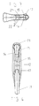
- la figure 1 est une vue en élévation du mousqueton selon l'invention, le doigt mobile étant représenté en position de fermeture ;
- la figure 2 est une vue identique de la figure 1 en position d'ouverture du doigt ;
- la figure 3 montre une vue de dessus de la figure 1;
- la figure 4 illustre une vue de profil de la figure 1.
- Figure 1 is an elevational view of the carabiner according to the invention, the movable finger being shown in the closed position;
- Figure 2 is an identical view of Figure 1 in the open position of the finger;
- Figure 3 shows a top view of Figure 1;
- FIG. 4 illustrates a side view of FIG. 1.
Sur les figures 1 à 4, un mousqueton 10 utilisé pour le portage d'accessoires
d'assurance, comporte un corps 11 en forme de crochet et un doigt 12 mobile
articulé à l'une des extrémités 13 du corps 11 pour fermer ou ouvrir l'ouverture
d'accès du crochet.In Figures 1 to 4, a
À titre d'exemple, le doigt 12 est réalisé en fil d'acier conformé selon une
épingle. Elle est dotée de deux ergots 14, 15 recourbés en équerre et introduits
dans des orifices décalés, ménagés à la partie supérieure dans l'extrémité 13.
Le doigt 12 comporte de plus une tête d'accrochage 16 coopérant en position de
fermeture avec l'extrémité inférieure 17 du corps 11. Le montage excentré des
ergots 14, 15 constitue un moyen de rappel élastique du doigt 12 vers la
position de fermeture.By way of example, the
A l'intérieur du corps 11, se trouve une patte de retenue 18 attachée à la partie
supérieure du corps 11, et s'étendant en regard de la branche latérale 19 à
l'opposé du doigt 12. La patte de retenue 18 possède une longueur inférieure à
celle de la branche latérale 19, et définit avec celle-ci une rainure 20.
L'épaisseur de la rainure 20 est sensiblement uniforme, de manière à permettre
l'insertion de la patte de retenue 18 sur un élément support (non représenté),
par exemple, une ceinture ou un harnais.Inside the
L'extrémité de la patte de retenue 18 est avantageusement incurvée pour
faciliter la mise en place sur l'élément support.The end of the
La partie supérieure du corps 11 comporte une surface de support 21 externe
sensiblement plane pour autoriser le rangement provisoire des accessoires
après ouverture du doigt 12. De préférence, la surface de support 21 est
équipée d'une pluralité de nervures 22 pour le rangement côte à côte des
accessoires.The
L'axe d'articulation du doigt 12 mobile est agencé avantageusement à la partie
supérieure du corps, et l'ouverture s'effectue vers l'intérieur du corps 11 sans
que le doigt 12 vienne en butée contre la patte de retenue 1 (figure 2).The axis of articulation of the
Un trou 25 est ménagé dans la partie supérieure du corps 11 pour autoriser
l'accrochage d'une ficelle destinée à sécuriser les accessoires et outils
transportés.A
Claims (9)
caractérisé en ce que le corps (11) est équipé d'une patte de retenue (18) attachée à la partie supérieure et s'étendant en regard de la branche latérale (19) à l'opposé du doigt (12), de manière à définir une rainure (20) destinée à être insérée sur un élément support pour assurer l'immobilisation du corps (11).Carabiner for use in climbing and for work at heights, comprising a hook-shaped body (11) for hooking a plurality of insurance accessories, a movable finger (12) hinged at one end (13) of the body for closing or opening the access passage of the hook, and biasing means biasing the finger (12) towards the closed position,
characterized in that the body (11) is provided with a retaining tab (18) attached to the upper part and extending facing the lateral branch (19) opposite the finger (12), so as to defining a groove (20) to be inserted on a support member to secure the body (11).
Applications Claiming Priority (2)
| Application Number | Priority Date | Filing Date | Title |
|---|---|---|---|
| FR0311658 | 2003-10-06 | ||
| FR0311658A FR2860562B1 (en) | 2003-10-06 | 2003-10-06 | CARRIER ACCESSORY HOLDER |
Publications (2)
| Publication Number | Publication Date |
|---|---|
| EP1522748A1 true EP1522748A1 (en) | 2005-04-13 |
| EP1522748B1 EP1522748B1 (en) | 2006-06-28 |
Family
ID=34307437
Family Applications (1)
| Application Number | Title | Priority Date | Filing Date |
|---|---|---|---|
| EP04354034A Expired - Lifetime EP1522748B1 (en) | 2003-10-06 | 2004-09-22 | Snap hook with additional carrying function |
Country Status (5)
| Country | Link |
|---|---|
| US (1) | US7082647B2 (en) |
| EP (1) | EP1522748B1 (en) |
| DE (1) | DE602004001377T2 (en) |
| ES (1) | ES2267021T3 (en) |
| FR (1) | FR2860562B1 (en) |
Cited By (3)
| Publication number | Priority date | Publication date | Assignee | Title |
|---|---|---|---|---|
| EP3159048A1 (en) | 2015-10-19 | 2017-04-26 | Zedel | Material-holder device which can be adapted to a climbing harness |
| US10233964B2 (en) | 2016-05-23 | 2019-03-19 | Batz Corporation | Carabiner |
| EP3936733A1 (en) * | 2020-07-07 | 2022-01-12 | Zedel | Equipment holder device |
Families Citing this family (5)
| Publication number | Priority date | Publication date | Assignee | Title |
|---|---|---|---|---|
| GB2530558B (en) * | 2014-09-26 | 2017-04-26 | Treemagineers Ltd | Carabiner |
| DE202016102724U1 (en) | 2016-05-23 | 2016-07-14 | Schmitz Gmbh | carabiner |
| WO2018160665A1 (en) * | 2017-02-28 | 2018-09-07 | Horizon Global Americas Inc. | Self-closing, single loop hook |
| CN108834668A (en) * | 2018-06-02 | 2018-11-20 | 郑州久昌电子科技股份有限公司 | Home for destitute planting shed steel wire hanging device |
| GB2580885A (en) * | 2018-12-11 | 2020-08-05 | Zzion Ltd | Tool holder |
Citations (4)
| Publication number | Priority date | Publication date | Assignee | Title |
|---|---|---|---|---|
| US3090826A (en) * | 1960-01-26 | 1963-05-21 | United Carr Fastener Corp | Wiring fastener |
| US5187844A (en) * | 1990-06-20 | 1993-02-23 | Etablissements Ludger Simond, Societe Anonyme | Self-locking snap-hook |
| US5384943A (en) * | 1992-07-29 | 1995-01-31 | Etablissements Ludger Simond, S.A. | Snap-hook with self-locking roller |
| DE20108512U1 (en) * | 2001-05-21 | 2001-12-13 | Rottefella A/S, Klokkarstua | Snap hook |
Family Cites Families (9)
| Publication number | Priority date | Publication date | Assignee | Title |
|---|---|---|---|---|
| US437380A (en) * | 1890-09-30 | Charles g | ||
| US1349468A (en) * | 1919-10-06 | 1920-08-10 | William N Morrison | Key-ring holder |
| US1622532A (en) * | 1926-01-11 | 1927-03-29 | Frank W Morse | Quick-releasing key holder |
| US1834863A (en) * | 1931-07-30 | 1931-12-01 | David C Roberts Jr | Key ring hook |
| US4113156A (en) * | 1977-02-03 | 1978-09-12 | Teodoro Guzman Brito | Key ring holder |
| US4319704A (en) * | 1980-10-20 | 1982-03-16 | Rosen Louis M | Support member |
| US5619774A (en) * | 1995-01-25 | 1997-04-15 | Xcell, Llc | Eyeglass retaining apparatus |
| US5913479A (en) * | 1996-09-18 | 1999-06-22 | Westwood, Iii; Samuel M. | Snap hook with pivotal gate |
| US6601274B2 (en) * | 2001-11-27 | 2003-08-05 | Capewell Components Company, Llc | Static line snap |
-
2003
- 2003-10-06 FR FR0311658A patent/FR2860562B1/en not_active Expired - Lifetime
-
2004
- 2004-09-22 ES ES04354034T patent/ES2267021T3/en not_active Expired - Lifetime
- 2004-09-22 EP EP04354034A patent/EP1522748B1/en not_active Expired - Lifetime
- 2004-09-22 DE DE602004001377T patent/DE602004001377T2/en not_active Expired - Lifetime
- 2004-09-27 US US10/949,355 patent/US7082647B2/en not_active Expired - Lifetime
Patent Citations (4)
| Publication number | Priority date | Publication date | Assignee | Title |
|---|---|---|---|---|
| US3090826A (en) * | 1960-01-26 | 1963-05-21 | United Carr Fastener Corp | Wiring fastener |
| US5187844A (en) * | 1990-06-20 | 1993-02-23 | Etablissements Ludger Simond, Societe Anonyme | Self-locking snap-hook |
| US5384943A (en) * | 1992-07-29 | 1995-01-31 | Etablissements Ludger Simond, S.A. | Snap-hook with self-locking roller |
| DE20108512U1 (en) * | 2001-05-21 | 2001-12-13 | Rottefella A/S, Klokkarstua | Snap hook |
Cited By (5)
| Publication number | Priority date | Publication date | Assignee | Title |
|---|---|---|---|---|
| EP3159048A1 (en) | 2015-10-19 | 2017-04-26 | Zedel | Material-holder device which can be adapted to a climbing harness |
| US10233964B2 (en) | 2016-05-23 | 2019-03-19 | Batz Corporation | Carabiner |
| EP3936733A1 (en) * | 2020-07-07 | 2022-01-12 | Zedel | Equipment holder device |
| FR3112370A1 (en) * | 2020-07-07 | 2022-01-14 | Zedel | EQUIPMENT DEVICE |
| US11849833B2 (en) | 2020-07-07 | 2023-12-26 | Zedel | Gear sling device |
Also Published As
| Publication number | Publication date |
|---|---|
| EP1522748B1 (en) | 2006-06-28 |
| DE602004001377D1 (en) | 2006-08-10 |
| US20050071961A1 (en) | 2005-04-07 |
| DE602004001377T2 (en) | 2007-06-14 |
| FR2860562B1 (en) | 2005-12-23 |
| FR2860562A1 (en) | 2005-04-08 |
| US7082647B2 (en) | 2006-08-01 |
| ES2267021T3 (en) | 2007-03-01 |
Similar Documents
| Publication | Publication Date | Title |
|---|---|---|
| EP2535603B1 (en) | Locking carabiner | |
| EP2189186B1 (en) | Multifunctional securing apparatus for ropes | |
| EP1344951A1 (en) | Snap hook equipped with a locking ring with a separation leg | |
| EP2535602B1 (en) | Locking carabiner | |
| EP3466493A1 (en) | Harness | |
| EP1522748B1 (en) | Snap hook with additional carrying function | |
| US20110113604A1 (en) | Easy clip carabiner with a retractable trigger | |
| EP3211267B1 (en) | Safety lanyard with an improved swivel | |
| US11759663B1 (en) | Bucket hook with tether hole | |
| WO2018042113A1 (en) | Coupling system, equipment assembly rigidly connected to a user, coupling system and kiteboarding kite bar | |
| EP3001046B1 (en) | Carabiner with improved eye | |
| EP3159048B1 (en) | Material-holder device which can be adapted to a climbing harness | |
| EP3043673A2 (en) | Bottle holder | |
| EP3421824A1 (en) | Secure carabiner | |
| WO2011064503A1 (en) | Magnetic device for automatically coupling a leash to an animal collar | |
| FR2855580A3 (en) | Chain hanging hook for suspending object, has buckle with penetration groove that traverses two interior sides and exterior side of buckle, and moving axle positioned by pin and including notch | |
| EP3913253B1 (en) | Clasp for elastic tensioner and tensioner comprising same | |
| FR2814344A1 (en) | BELT CONNECTION DEVICE | |
| FR2976184A1 (en) | Mounting device adapter for attaching safety straps of person to fall protection device, has lateral hooks opposed on sides of central vertical portion of coupling plate, and pin locked in closed position by locking lever | |
| EP3290629B1 (en) | Coiler for strap, cord or analogous | |
| FR3093646A1 (en) | Removal device for placing a climbing rope inside a carabiner | |
| EP1013504B1 (en) | Garment rail for vehicle body structure | |
| FR2879507A1 (en) | Motor vehicle`s snow chain, has chain hoop closed by closing and tensioning device with connecting part and case, where case forms handle constituted of two semi handles separated by line passing through duct housing elastic strand | |
| WO2005025818A2 (en) | Clasp knife provided with a rotational ring forming an improved guide holding notch | |
| FR2702100A1 (en) | Device for anchoring a power (electric) cable |
Legal Events
| Date | Code | Title | Description |
|---|---|---|---|
| PUAI | Public reference made under article 153(3) epc to a published international application that has entered the european phase |
Free format text: ORIGINAL CODE: 0009012 |
|
| AK | Designated contracting states |
Kind code of ref document: A1 Designated state(s): AT BE BG CH CY CZ DE DK EE ES FI FR GB GR HU IE IT LI LU MC NL PL PT RO SE SI SK TR |
|
| AX | Request for extension of the european patent |
Extension state: AL HR LT LV MK |
|
| 17P | Request for examination filed |
Effective date: 20050723 |
|
| GRAP | Despatch of communication of intention to grant a patent |
Free format text: ORIGINAL CODE: EPIDOSNIGR1 |
|
| GRAS | Grant fee paid |
Free format text: ORIGINAL CODE: EPIDOSNIGR3 |
|
| AKX | Designation fees paid |
Designated state(s): CZ DE ES GB IT |
|
| GRAA | (expected) grant |
Free format text: ORIGINAL CODE: 0009210 |
|
| AK | Designated contracting states |
Kind code of ref document: B1 Designated state(s): CZ DE ES GB IT |
|
| REG | Reference to a national code |
Ref country code: GB Ref legal event code: FG4D Free format text: NOT ENGLISH |
|
| REF | Corresponds to: |
Ref document number: 602004001377 Country of ref document: DE Date of ref document: 20060810 Kind code of ref document: P |
|
| GBT | Gb: translation of ep patent filed (gb section 77(6)(a)/1977) |
Effective date: 20060924 |
|
| REG | Reference to a national code |
Ref country code: ES Ref legal event code: FG2A Ref document number: 2267021 Country of ref document: ES Kind code of ref document: T3 |
|
| PLBE | No opposition filed within time limit |
Free format text: ORIGINAL CODE: 0009261 |
|
| STAA | Information on the status of an ep patent application or granted ep patent |
Free format text: STATUS: NO OPPOSITION FILED WITHIN TIME LIMIT |
|
| 26N | No opposition filed |
Effective date: 20070329 |
|
| PGFP | Annual fee paid to national office [announced via postgrant information from national office to epo] |
Ref country code: IT Payment date: 20230810 Year of fee payment: 20 Ref country code: GB Payment date: 20230803 Year of fee payment: 20 Ref country code: CZ Payment date: 20230831 Year of fee payment: 20 |
|
| PGFP | Annual fee paid to national office [announced via postgrant information from national office to epo] |
Ref country code: DE Payment date: 20230726 Year of fee payment: 20 |
|
| PGFP | Annual fee paid to national office [announced via postgrant information from national office to epo] |
Ref country code: ES Payment date: 20231004 Year of fee payment: 20 |