EP1522745A1 - Schraube mit einem mit zwei das Anziehen derselben erlaubenden Strukturen versehenem Kopf - Google Patents
Schraube mit einem mit zwei das Anziehen derselben erlaubenden Strukturen versehenem Kopf Download PDFInfo
- Publication number
- EP1522745A1 EP1522745A1 EP04292368A EP04292368A EP1522745A1 EP 1522745 A1 EP1522745 A1 EP 1522745A1 EP 04292368 A EP04292368 A EP 04292368A EP 04292368 A EP04292368 A EP 04292368A EP 1522745 A1 EP1522745 A1 EP 1522745A1
- Authority
- EP
- European Patent Office
- Prior art keywords
- threaded screw
- screw fastener
- head
- drive means
- washer member
- Prior art date
- Legal status (The legal status is an assumption and is not a legal conclusion. Google has not performed a legal analysis and makes no representation as to the accuracy of the status listed.)
- Withdrawn
Links
- 230000009977 dual effect Effects 0.000 title claims abstract description 11
- 230000002093 peripheral effect Effects 0.000 claims description 22
- 239000000758 substrate Substances 0.000 claims description 19
- 238000009434 installation Methods 0.000 description 28
- 230000007613 environmental effect Effects 0.000 description 22
- 239000012528 membrane Substances 0.000 description 22
- 238000003780 insertion Methods 0.000 description 18
- 230000037431 insertion Effects 0.000 description 18
- 238000004519 manufacturing process Methods 0.000 description 10
- 239000000463 material Substances 0.000 description 9
- 230000002829 reductive effect Effects 0.000 description 5
- 230000003247 decreasing effect Effects 0.000 description 4
- 230000013011 mating Effects 0.000 description 4
- 230000036961 partial effect Effects 0.000 description 4
- 230000000694 effects Effects 0.000 description 3
- 230000001747 exhibiting effect Effects 0.000 description 3
- 230000000712 assembly Effects 0.000 description 2
- 238000000429 assembly Methods 0.000 description 2
- 230000004323 axial length Effects 0.000 description 2
- 230000000644 propagated effect Effects 0.000 description 2
- 229910000831 Steel Inorganic materials 0.000 description 1
- 230000002411 adverse Effects 0.000 description 1
- XAGFODPZIPBFFR-UHFFFAOYSA-N aluminium Chemical compound [Al] XAGFODPZIPBFFR-UHFFFAOYSA-N 0.000 description 1
- 229910052782 aluminium Inorganic materials 0.000 description 1
- 239000002131 composite material Substances 0.000 description 1
- 230000006866 deterioration Effects 0.000 description 1
- -1 for example Substances 0.000 description 1
- 238000009413 insulation Methods 0.000 description 1
- 238000012986 modification Methods 0.000 description 1
- 230000004048 modification Effects 0.000 description 1
- 238000004321 preservation Methods 0.000 description 1
- 230000001681 protective effect Effects 0.000 description 1
- 230000000717 retained effect Effects 0.000 description 1
- 239000010959 steel Substances 0.000 description 1
- 239000012815 thermoplastic material Substances 0.000 description 1
- 239000002023 wood Substances 0.000 description 1
Images


Classifications
-
- F—MECHANICAL ENGINEERING; LIGHTING; HEATING; WEAPONS; BLASTING
- F16—ENGINEERING ELEMENTS AND UNITS; GENERAL MEASURES FOR PRODUCING AND MAINTAINING EFFECTIVE FUNCTIONING OF MACHINES OR INSTALLATIONS; THERMAL INSULATION IN GENERAL
- F16B—DEVICES FOR FASTENING OR SECURING CONSTRUCTIONAL ELEMENTS OR MACHINE PARTS TOGETHER, e.g. NAILS, BOLTS, CIRCLIPS, CLAMPS, CLIPS OR WEDGES; JOINTS OR JOINTING
- F16B23/00—Specially shaped nuts or heads of bolts or screws for rotations by a tool
- F16B23/0092—Specially shaped nuts or heads of bolts or screws for rotations by a tool with a head engageable by two or more different tools
-
- F—MECHANICAL ENGINEERING; LIGHTING; HEATING; WEAPONS; BLASTING
- F16—ENGINEERING ELEMENTS AND UNITS; GENERAL MEASURES FOR PRODUCING AND MAINTAINING EFFECTIVE FUNCTIONING OF MACHINES OR INSTALLATIONS; THERMAL INSULATION IN GENERAL
- F16B—DEVICES FOR FASTENING OR SECURING CONSTRUCTIONAL ELEMENTS OR MACHINE PARTS TOGETHER, e.g. NAILS, BOLTS, CIRCLIPS, CLAMPS, CLIPS OR WEDGES; JOINTS OR JOINTING
- F16B33/00—Features common to bolt and nut
- F16B33/02—Shape of thread; Special thread-forms
Definitions
- the present invention relates generally to threaded screw fasteners, and more particularly to a new and improved threaded screw fastener which has unique and novel buttress thread structure which effectively provides the new and improved threaded screw fastener with reduced installation or insertion torque characteristics, and which also effectively provides the new and improved threaded screw fastener with enhanced pull-out resistance characteristics, whereby the new and improved threaded screw fastener can be easily and readily inserted or installed, and retained, within various different substrates, such as, for example, steel, concrete, aluminum, wood, and thermoplastic materials, and still further, the new and improved threaded screw fastener has unique and novel head structure which not only enables the new and improved threaded screw fastener to be inserted or installed within a substrate as a result of being capable of being alternatively utilized either with a Phillips head drive socket implement or tool, or with a hexagonal drive socket implement or tool, but in addition, the head structure comprises low-profile domed structure such that when the new and improved threaded screw fastener is utilized to secure
- a rotational drive force must be imparted to the threaded screw fastener.
- the two most common means for imparting rotational drive forces to threaded screw fasteners is either by means of a hexagonal drive socket implement or tool which is adapted to engage a corresponding hexagonally configured head portion of the fastener, or alternatively, by means of a Phillips head drive socket implement or tool which is adapted to engage a correspondingly configured Phillips head portion of the fastener.
- FIGURES 1 and 2 Typical threaded screw fasteners, respectively having such a hexagonally configured head portion, or a Phillips head portion, are disclosed within FIGURES 1 and 2 . More particularly, a first conventional PRIOR ART threaded fastener is disclosed within FIGURE 1 and is generally indicated by the reference character 10.
- the threaded fastener 10 is seen to comprise a threaded shank portion 12, and a head portion 14.
- the head portion 14 has a hexagonal cross-sectional configuration, and it is also seen that the hexagonally-configured head portion 14 has a constant depth dimension D, as defined between vertically spaced, horizontally disposed, upper and lower planar surfaces 16,18. As a result of such structure, the hexagonally-configured head portion 14 exhibits a relatively large profile.
- FIGURE 2 a second conventional PRIOR ART threaded fastener is disclosed within FIGURE 2 and is generally indicated by the reference character 110.
- the threaded fastener 110 is seen to comprise a similarly threaded shank portion 112, and a head portion 114.
- the head portion 114 is provided with a substantially X-shaped slotted region 116 which is recessed within the head portion 114 so as to be capable of accommodating a Phillips head drive socket implement or tool, and it is additionally seen that the upper surface 118 of the head portion 114 has a substantially domed configuration which circumferentially slopes downwardly so as to terminate in a relatively thin-dimensioned peripheral surface 120.
- the conventional PRIOR ART threaded fasteners 10,110 normally exhibit satisfactory operational or performance characteristics, the conventional PRIOR ART threaded fasteners 10,110 do in fact exhibit some significant operational drawbacks. For example, different field personnel usually prefer to use a particular one of the two different types of conventional PRIOR ART threaded screw fasteners, and accordingly have suitable drive socket implements or tools for drivingly engaging the head portions of the particular threaded screw fasteners.
- the vertically spaced, horizontally disposed, upper and lower planar surfaces 16,18, together with the six, vertically oriented side surfaces or facets 20 of the head portion 14, define a plurality of vertically spaced, upper and lower peripheral edge portions 22, wherein each one of the upper and lower peripheral edge portions 22 defines, includes, or comprises a 90° angle. It is also seen that adjacent pairs of the side surfaces or facets 20,20 define a plurality of vertically oriented edge regions or loci 24 therebetween, whereby the upper and lower termini of the vertically oriented edge regions or loci 24 define sharply pointed corner loci 26.
- the peripheral edge portions 22, defined between the vertically oriented side surfaces or facets 20 and the upper planar surface 16, as well as the upper corner loci 26 disposed within the plane of the upper planar surface 16, present sharply configured structures.
- the threaded screw fastener 210 comprises a shank portion 212 upon which a plurality of buttress-type threads 214 are formed.
- each one of the conventional buttress-type threads 214 is seen to comprise a slightly inclined rearward flank surface 216 and a significantly inclined forward flank surface 218, a predetermined thread pitch P, as measured between the same points of successive thread crest portions 220, and a predetermined spacing S as determined between the root region of the rearward flank surface 216 of a particular thread and the root region of the forward flank surface 218 of the next or successive thread.
- the rear flank surface 216 play critical roles in, or effectively determine, the pull-out resistance characteristics or properties of the fastener 210, while the forward flank surface 218, and the spacing S, likewise play critical roles in, or effectively determine, the installation or insertion torque characteristics or properties of the fastener 210.
- the ideal or perfectly designed fastener will exhibit relatively high pull-out resistance characteristics or properties, while concomitantly exhibiting relatively low installation or insertion torque characteristics or properties.
- conventional or PRIOR ART fasteners such as, for example, the fastener 210, as disclosed within FIGURES 3 and 4 and characterized by means of the conventional or PRIOR ART buttress thread structure, cannot effectively simultaneously achieve the aforenoted relatively high pull-out resistance characteristics or properties and the relatively low insertion or installation torque characteristics or properties.
- the diametrical extent of the threaded screw fastener 210 would have to be increased, that is, the external diametrical dimensions or extents of both the shank portion 212 and the threads 214 as determined by means of the crest portions 220 thereof.
- Increasing the diametrical dimension or extent of the threaded screw fastener 210 is not desirable or viable for several reasons. Firstly, for example, increasing the diametrical dimension or extent of the threaded screw fastener 210 obviously increases the amount of material that is required to be structurally incorporated within each fastener 210, and therefore the manufacturing or fabrication costs per fastener are correspondingly increased.
- increasing the diametrical dimension or extent of the threaded screw fastener 210 also serves to increase the installation or insertion torque characteristics or properties of the fastener 210, which, of course, is precisely the opposite objective that is sought to be achieved in connection with the threaded screw fastener 210.
- Another object of the present invention is to provide a new and improved threaded screw fastener, and a drive socket implement or tool therefor, which effectively overcomes the various operational and manufacturing drawbacks and disadvantages characteristic of conventional PRIOR ART threaded screw fasteners and drive socket implements or tools.
- An additional object of the present invention is to provide a new and improved threaded screw fastener which is provided with head structure that permits the threaded screw fastener to be rotatably driven by means of alternative drive socket implements or tools, such as, for example, hexagonally configured socket implements or tools, or Phillips head configured socket implements or tools, whereby only a single type of threaded screw fastener is needed at a field installation or job site in view of the fact that the single type of threaded screw fastener can be inserted or installed within a substrate regardless of the type of drive socket implement or tool that a particular workman may be using at the field installation or job site.
- alternative drive socket implements or tools such as, for example, hexagonally configured socket implements or tools, or Phillips head configured socket implements or tools
- a further object of the present invention is to provide a new and improved threaded screw fastener which is provided with unique and novel thread structure which permits the threaded screw fastener to exhibit enhanced pull-out resistance characteristics or properties while simultaneously exhibiting reduced installation or insertion torque characteristics or properties.
- a last object of the present invention is to provide a new and improved threaded screw fastener which is provided with unique and novel thread structure which permits the threaded screw fastener to exhibit enhanced pull-out resistance characteristics or properties while simultaneously exhibiting reduced installation or insertion torque characteristics or properties, and without necessarily increasing the diametrical extent of the threaded screw fastener wherein the threaded screw fastener can be economically manufactured or fabricated due to an effective conservation, preservation, or minimalization of the amount material required to manufacture or fabricate the threaded screw fastener.
- a new and improved threaded screw fastener which comprises a head portion that has low profile domed structure integrally incorporated therein, and wherein further, the head portion also has unique and novel combination structure which permits the threaded screw fastener to be rotatably driven either by means of a rotary drive tool having, for example, hexagonally configured drive structure integrally incorporated therein, or alternatively by means of a rotary drive tool having, for example, Phillips head drive structure integrally incorporated therein.
- the threaded screw fastener having such combination head structure, can be drivingly inserted or installed within substrates regardless of the particular drive socket implement or tool being utilized by field installation or job site personnel.
- a new and improved drive socket implement or tool which has integrally incorporated therein both hexagonally configured drive structure, Phillips head drive structure, and domed contour structure for not only structurally accommodating both the hexagonally configured structure and the Phillips head structure integrally incorporated upon the head portion of the threaded screw fastener, but in addition, for accommodating the low profile domed structure of the head portion of the threaded screw fastener.
- the threaded screw fastener also comprises thread structure wherein each thread of the threaded screw fastener comprises unique and novel rearward and forward flank surfaces which effectively serve to simultaneously enhance the pull-out resistance characteristics or properties of the threaded screw fastener while reducing the installation or insertion torque characteristics or properties of the threaded screw fastener.
- a first embodiment of a new and improved threaded screw fastener constructed in accordance with the principles and teachings of the present invention, is disclosed and is generally indicated by the reference character 310.
- the first embodiment of the new and improved threaded screw fastener 310 of the present invention has incorporated therein structural features which are somewhat similar to those structural features characteristic of the conventional PRIOR ART threaded screw fasteners 10,110 as respectively disclosed within FIGURES 1 and 2 , such structural features of the first embodiment threaded screw fastener 310 will be designated by similar or corresponding reference characters except that they will be within the 300 series.
- the new and improved first embodiment threaded screw fastener 310 is seen to comprise a threaded shank portion 312, and a head portion 314, wherein the head portion 314 has integrally formed thereon a first embodiment of combination structure which permits the head portion 314 to be alternatively engaged either by means of a hexagonally configured drive socket implement or tool, or by means of a Phillips head drive socket implement or tool, whereby rotary drive can be imparted to the first embodiment threaded screw fastener 310 so as to drivingly install or insert the first embodiment threaded screw fastener 310 into a substrate.
- the head portion 314 of the first embodiment threaded screw fastener 310 comprises a circular washer member 313 integrally formed upon the upper end of the threaded shank portion 312, and upstanding, combination fastener drive structure is disposed atop the circular washer member 313 such that the circular washer member 313 effectively forms an annular flanged or shoulder portion surrounding the upstanding, combination fastener drive structure.
- the upstanding, combination fastener drive structure is seen to comprise a centrally located drive member 318 which comprises six vertically or axially oriented external sides or facets 320 such that the drive member 318 has a substantially hexagonal cross-sectional configuration, and a substantially X-shaped recessed section 328 is internally formed at an axially central location within the hexagonally configured drive member 318 so as to define a Phillips head drive member.
- the upper surface portion 316 of the centrally located hexagonally configured drive member 318 which is disposed substantially transversely or perpendicular to the longitudinal axis of the threaded screw fastener 310, actually has a domed configuration such that the upper surface portion 316 slopes downwardly in a circumferential manner from the axially located substantially X-shaped recessed section 328 toward the six vertically or axially oriented external sides or facets 320 which effectively form the outer periphery of the hexagonally configured drive member 318.
- the vertical height dimension of the hexagonally configured drive member 318 is relatively small.
- the upper edge portions 322 of the six vertically or axially oriented external sides or facets 320 of the hexagonally configured drive member 318 which substantially correspond to the upper edge portions 22 of the sides or facets 20 of the threaded screw fastener 10 as disclosed within FIGURE 1, are not disposed at the uppermost elevational level of the threaded screw fastener 310.
- the upper edge regions 322 of the hexagonally configured drive member 318 as defined at the junctions of the upper surface portion 316 and each one of the external sides or facets 320 of the hexagonally configured drive member 318, do not comprise 90° angles.
- the upper corner regions 326 are likewise disposed at an elevational level which is beneath the uppermost elevational level of the threaded screw fastener 310.
- the waterproof or environmental membranes will be forced primarily into contact with and thereby encounter the circumferentially extending, downwardly sloped upper surface portions 316 of the threaded screw fasteners 310, and will not be primarily forced into contact with or encounter the upper edge portions 322 of the six vertically or axially oriented external sides or facets of the hexagonally configured drive member 318.
- first embodiment threaded screw fastener 310 with the combination fastener drive structure 318,328 that permits the first embodiment threaded screw fastener 310 to be rotatably driven by means of alternative drive socket implements or tools, such as, for example, hexagonally configured socket implements or tools, or by means of Phillips head configured socket implements or tools, only a single type of threaded screw fastener 310 is needed at field installation or job site locations in view of the fact that the single type of threaded screw fastener 310 can be inserted or installed within a substrate regardless of the type of drive socket implement or tool that a particular workman or field personnel may be using at the field installation or job site.
- alternative drive socket implements or tools such as, for example, hexagonally configured socket implements or tools, or by means of Phillips head configured socket implements or tools
- FIGURE 6 a second embodiment of a new and improved threaded screw fastener, constructed in accordance with the principles and teachings of the present invention so as to be functionally similar to the first embodiment of the new and improved threaded screw fastener 310 as disclosed within FIGURE 5 , is disclosed and is generally indicated by the reference character 410. It is to be noted that in view of the fact that the second embodiment threaded screw fastener 410 is structurally similar to the first embodiment threaded screw fastener 310, a detailed description of the same, except for those structural features unique to the second embodiment threaded screw fastener 410, will be omitted for brevity purposes.
- the new and improved second embodiment threaded screw fastener 410 is seen to comprise a threaded shank portion 412, and a head portion 414, wherein the head portion 414 has integrally formed thereon a second embodiment of combination structure which permits the head portion 414 to be alternatively engaged either by means of a hexagonally configured drive socket implement or tool, or by means of a Phillips head drive socket implement or tool, whereby rotary drive can be imparted to the second embodiment threaded screw fastener 410 so as to drivingly install or insert the second embodiment threaded screw fastener 410 into a substrate.
- the head portion 414 of the second embodiment threaded screw fastener 410 comprises an upper surface portion 416 having a domed configuration which slopes downwardly in a circumferential manner from an axially central region of the head portion 414 toward the peripheral region of the head portion 414 as effectively defined by means of an underlying washer member 413.
- the combination fastener drive structure of .the second embodiment threaded screw fastener 410 is seen to comprise substantially X-shaped recessed structure 428 which is defined within the axially central region of the head portion 414 so as to effectively define a Phillips head drive member, and six vertically or axially oriented external sides or facets 420 which are formed upon the external periphery of the washer member 413 whereby the external periphery of the head portion 414 effectively defines a drive member 418 which has a substantially hexagonal cross-sectional configuration.
- the vertical height dimension of the hexagonally configured drive member 418 is relatively small.
- the upper edge portions 422 of the six vertically or axially oriented external sides or facets 420 of the hexagonally configured drive member 418 which substantially correspond to the upper edge portions 322 of the sides or facets 320 of the threaded screw fastener 310 as disclosed within FIGURE 5, are not disposed at the uppermost elevational level of the threaded screw fastener 410.
- the upper edge regions 422 of the hexagonally configured drive member 418 do not comprise 90° angles.
- the individual vertically or axially oriented external sides or facets 420 of the hexagonally configured drive member 418 do not abut each other in a circumferential manner but, to the contrary, are effectively separated from each other by means of arcuate portions 430 of the washer member 413.
- FIGURE 7 a third embodiment of a new and improved threaded screw fastener, also constructed in accordance with the principles and teachings of the present invention so as to be functionally similar to the first and second embodiments of the new and improved threaded screw fasteners 310,410 as disclosed within FIGURES 5 and 6, is disclosed and is generally indicated by the reference character 510.
- the third embodiment threaded screw fastener 510 is structurally similar to the first and second embodiment threaded screw fasteners 310,410, a detailed description of the same, except for those structural features unique to the second embodiment threaded screw fastener 510, will be omitted for brevity purposes.
- the new and improved third embodiment threaded screw fastener 510 is seen to comprise a threaded shank portion 512, and a head portion 514, wherein the head portion 514 has integrally formed thereon a third embodiment of combination structure which permits the head portion 514 to be alternatively engaged either by means of a hexagonally configured drive socket implement or tool, or by means of a Phillips head drive socket implement or tool, whereby rotary drive can be imparted to the third embodiment threaded screw fastener 510 so as to drivingly install or insert the third embodiment threaded screw fastener 510 into a substrate.
- the head portion 514 of the third embodiment threaded screw fastener 510 effectively comprises hybrid structure with respect to the structure comprising the head portions 314,414 of the first and second embodiment threaded screw fasteners 310,410.
- the head portion 514 of the third embodiment threaded screw fastener 510 comprises a circular washer member 513 which is integrally formed upon the upper end of the threaded shank portion 512, and upstanding, combination fastener drive structure is disposed atop the circular washer member 513 such that the circular washer member 513 effectively forms an annular flanged portion which surrounds the upstanding, combination fastener drive structure.
- the upstanding, combination fastener drive structure is seen to comprise a first drive member 518 which comprises six vertically or axially oriented external sides or facets 520 such that the first drive member 518 has a substantially hexagonal cross-sectional configuration, and a second substantially X-shaped recessed section 528 is internally formed at an axially central location within the hexagonally configured drive member 518 so as to define a Phillips head drive member.
- the upper surface portion 516 of the centrally located hexagonally configured drive member 518 which is disposed substantially transversely or perpendicular to the longitudinal axis of the threaded screw fastener 510, has a domed configuration, similar to the upper surface portions 316,416 of the threaded screw fasteners 310, 410, such that the upper surface portion 516 slopes downwardly in a circumferential manner from the axially located substantially X-shaped recessed section 528 toward the six vertically or axially oriented external sides or facets 520 . which effectively form the outer periphery of the hexagonally configured drive member 518.
- the vertically or axially oriented external sides or facets 520 of the drive member 518 being defined within the peripheral surface of the circular washer member 513, as was the case with the vertically or axially oriented external sides or facets 420 with respect to the outer peripheral surface of the circular washer member 413, the vertically or axially oriented external sides or facets 520 of the drive member 518 are disposed atop the circular washer member 513 and are disposed slightly radially inwardly offset from the outer peripheral edge portion of the circular washer member 513.
- corner regions 526 defined between adjacent ones of the vertically or axially oriented external facets or sides 520 of the drive member 518 are effectively disposed at the peripheral edge of and within the plane of the circular washer member 513. Accordingly, the vertical height dimension of the hexagonally configured drive member 518, as defined by means of the axial extent of the six vertically or axially oriented external facets or sides 520 of the hexagonally configured drive member 518, is relatively small.
- the upper edge portions 522 of the six vertically or axially oriented external sides or facets 520 of the hexagonally configured drive member 518 are not disposed at the uppermost elevational level of the threaded screw fastener 510.
- the upper edge regions 522 of the hexagonally configured drive member 518 as defined at the junctions of the upper surface portion 516 and each one of the external sides or facets 520 of the hexagonally configured drive member 518, do not comprise 90° angles.
- the waterproof or environmental membranes will be forced into contact with and thereby encounter the circumferentially extending, downwardly sloped upper surface portions 516 of the threaded screw fasteners 510, and will not be forced into contact with or encounter any sharply pointed edge or corner regions of the six vertically or axially oriented external sides or facets of the hexagonally configured drive member 518. Therefore, cutting, piercing, and ultimate shredding or tearing of the waterproof or environmental membranes is effectively prevented.
- This mode of operation is of course facilitated or enabled in view of the fact that the single type of threaded screw fastener 510 can be inserted or installed within a substrate regardless of the type of drive socket implement or tool that a particular workman or field personnel may be using at the field installation or job site.
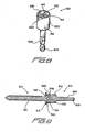
- a new and improved drive socket implement or tool for operatively engaging the head portion of any one of the threaded screw fasteners 310,410,510, as disclosed within FIGURES 5-7 , so as to impart a rotatable drive force thereto, is disclosed and is generally indicated by the reference character 610.
- the new and improved drive socket implement or tool 610 is seen to comprise a cylindrical housing 612 which is open at the front end thereof so as to define a socket member 614 therewithin for accommodating and operatively mating with at least some of the drive structure defined upon the head portion of any one of the aforenoted threaded screw fasteners 310,410,510.
- the new and improved drive socket implement or tool 610 is disclosed as being operatively engaged with the head portion 314 of the threaded screw fastener 310, the new and improved drive socket implement or tool 610 can be structurally configured so as to appropriately operatively engage the head portions 414, 514 of the threaded screw fasteners 410,510. More particularly, it is seen that the socket member 614 of the new and improved drive socket implement or tool 610 is provided with an annular or peripheral front face 616 which is disposed within a plane that is substantially perpendicular to the longitudinal axis of the socket implement or tool 610.
- Six inner peripheral wall members 618 of the socket member 614 are disposed within the immediate vicinity of the front face 616 of the socket implement or tool 610 so as to extend axially rearwardly from the front face 616 of the socket implement or tool 610, and in addition, the six inner peripheral wall members 618 are disposed within a circumferential array so as to effectively circumscribe a region within the socket member 614 which has a substantially hexagonal configuration. In this manner, when the new and improved socket implement or tool 610 is operatively engaged with the head portion 314 of the threaded screw fastener 310, the sides or facets 320 of the hexagonally configured drive member 318 can be drivingly engaged by means of the hexagonally arranged wall members 618 of the socket member 614.
- the socket member 614 is also provided with an axially located, forwardly extending, substantially X-shaped conical projection 620 which effectively defines a Phillips head screwdriver element which is adapted to operatively engage the X-shaped Phillips head recessed portion 328 defined within the head portion 314 of the threaded screw fastener 310 when, for example, the socket implement or tool 610 is operatively engaged with the head portion 314 of the threaded screw fastener 310 as disclosed within FIGURE 9 .
- the Phillips head screwdriver element 620 can be operatively used to engage the X-shaped Phillips head recessed portion 328 defined within the head portion 314 of the threaded screw fastener 310 in conjunction with the operative or driving engagement of the sides or facets 320 of the hexagonally configured drive member 318 of the head portion 314 of the threaded screw fastener 310 by means of the hexagonally arranged wall members 618 of the socket member 614.
- the socket member 614 comprises a concavely contoured mating surface 622 which is adapted to house or accommodate, for example, the domed upper surface portion 316 of the head portion 314 of the threaded screw fastener 310.
- socket member 614 may be provided with both the hexagonal drive means comprising the plurality of side wall members 618, as well as the Phillips head screwdriver element 620, in conjunction with the contoured mating surface 622, so as to properly drivingly engage the head portion 314 of the threaded screw fastener 310, only a single one of the drive means 618,620 truly needs to be provided in view of the fact that the threaded screw fastener 310 is provided with the dual drivable means 320, 328.
- the housing 612 is mounted upon the forward end of a shaft member 624, and that the rear end of the shaft member 624 is provided with a stem portion 626 for insertion within, for example, a suitable collet member, not shown, of a rotary drive tool, also not shown.
- a fourth embodiment of a new and improved threaded screw fastener constructed in accordance with the principles and teachings of the present invention is disclosed and is generally indicated by the reference character 710.
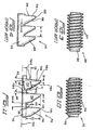
- the new and improved threaded screw fastener 710 comprises a shank portion 712 and a buttress thread portion 714, however, if the new and improved threaded screw fastener 710, as disclosed within FIGURES 10 and 11 , is compared to the conventional PRIOR ART threaded screw fastener 210 as disclosed within FIGURES 3 and 4 , it will be readily apparent that the structure of the individual threads 714 of the threaded screw fastener 710, as constructed in accordance with the principles and teachings of the present invention, is quite different from the structure of the individual threads 214 of the conventional PRIOR ART threaded screw fastener 210.
- the individual threads 214 of the threaded screw fastener 710 of the present invention comprise at least one, and preferably two, substantially perpendicular rearward planar flank surfaces 716-1,716-2, and dual, inclined forward planar flank surfaces 718-1,718-2.
- the longitudinal axis of the threaded screw fastener 710 is disclosed at 722, while a radius of the threaded screw fastener 710 is disclosed at 724. Accordingly, it can be appreciated that the angular extent or inclination of the radially outer forward flank surface 718-1 with respect to the radius 724 is designated by means of the angle A1, while the angular extent or inclination of the radially inner forward flank surface 718-2 with respect to the radius 724 is designated by means of the angle A2.
- the angular extent or inclination of the radially outer rearward flank surface 716-1 with respect to the radius 724 is designated by means of the angle A3
- the angular extent or inclination of the radially inner rearward flank surface 716-2 with respect to the radially outer rearward flank surface 716-1 is designated by means of the angle A4.
- each thread 714 is denoted by means of the linear dimension D1
- the radial extent or width of each thread 714 is denoted by means of the linear dimension D2
- the radial extent or width of the radially inner rearward flank surface 716-2 of each thread 714 is denoted by means of the linear dimension D3
- the axial extent or distance defined between the root portion of the rearward flank surface of a particular thread 714 and the root portion of the forward flank surface of an adjacent thread 714 is denoted by means of the linear space dimension D4.
- the radial extent or width of the radially inner forward flank surface 718-2 of each thread 714 is denoted by means of the linear dimension D5
- the radial extent or width of the radially outer forward flank surface 718-1 of each thread 714 is denoted by means of the linear dimension D6
- the axial extent or distance defined between each pair of adjacent threads 714,714 is denoted by means of the linear pitch dimension D7.
- the radially inner forward flank surface 718-2 due to the provision of, for example, the radially inner forward flank surface 718-2, wherein the same is disposed at the angular inclination A2, which is relatively steeper than the angular inclination A1 at which the radially outer forward flank surface 718-1 is disposed with respect to the radius 724, that is, the radially inner forward flank surface 718-2 is disposed so as to be more perpendicular with respect to the longitudinal axis 722 of the threaded screw fastener 710 than is the radially outer forward flank surface 718-1, then it can be appreciated that a portion of the forward flank surface, as denoted in phantom lines at 718-3, has in effect been removed when compared, for example, to the forward flank surface 218 of the standard buttress thread 210 as disclosed within FIGURE 4 .
- the radially inner rearward flank surface 716-2 is disposed at the angular inclination A4 with respect to the radially outer rearward flank surface 716-1, and that the radially outer rearward flank surface 716-1 is disposed at the angular inclination A3 with respect to the radius 724.
- the radially inner rearward flank surface 716-2 is disposed so as to be more perpendicular with respect to the longitudinal axis 722 of the threaded screw fastener 710 than is the radially outer rearward flank surface 716-1.
- the degree of perpendicularity of the rearward flank surfaces of the threads of a threaded screw fastener is significantly determinative of the pull-out resistance characteristics or properties of the threaded screw fastener, it can be appreciated that by providing the radially inner rearward flank surface 716-2 as a distinctly separate planar surface with respect to or separate from the radially outer rearward flank surface 716-1, and wherein, for example, the radially inner rearward flank surface 716-2 can be disposed substantially perpendicular to the longitudinal axis 722 of the threaded screw fastener 710 while the radially outer rearward flank surface 716-1 is disposed at some predetermined angle, other than 90° with respect to the longitudinal axis 722 of the threaded screw fastener 710, then enhanced pull-out resistance characteristics or properties of the threaded screw fastener 710 can be achieved.
- the pull-out resistance characteristics or properties of the threaded screw fastener 710 can likewise be adjusted or altered. For example, as the radial extent or width dimension D3 of the radially inner rearward flank surface 716-2 is increased, the pull-out resistance characteristics or properties of the threaded screw fastener 710 will likewise be increased.
- Similar pull-out resistance characteristics or properties of the threaded screw fastener 710 can also be achieved by correspondingly altering the radial extent or width dimension D2 of the threads 714, as defined between the root portions 726 of the threads 714 and the crest portions 720 of the threads 714.
- the pull-out resistance characteristics or properties of the threaded screw fastener 710 will likewise be increased.
- the pull-out resistance characteristics or properties of the threaded screw fastener 710 can also be achieved by altering the axial extent or distance defined between identical points defined upon each pair of adjacent threads 714,714 as denoted by means of the linear pitch dimension D7. More particularly, as the linear pitch dimension D7 is decreased, whereby an increased number of threads 714 per axial inch is effectively achieved, the pull-out resistance characteristics or properties of the threaded screw fastener 710 are correspondingly increased.
- the separate planar radially outer and radially inner rearward flank surfaces 716-1,716-2 can in effect be coplanar as a result, for example, where the angular inclination A4, as defined between the separate planar radially outer and radially inner rearward flank surfaces 716-1,716-2, is effectively 0°. In this manner, the separate planar radially outer and radially inner rearward flank surfaces 716-1,716-2 effectively become a single planar rearward flank surface.
- This single planar rearward flank surface of the threaded screw fastener 710 of the present invention is noted as being significantly different from the conventional PRIOR ART planar rearward flank surface 216 of the threaded screw fastener 210 in that the angular inclination A3 of such single planar rearward flank surface of the threaded screw fastener 710 of the present invention is such as to dispose the single planar rearward flank surface of the threaded screw fastener 710 of the present invention at an orientation which is substantially more perpendicular than that characteristic of the conventional PRIOR ART planar rearward flank surface 216 of the threaded screw fastener 210.
- each threaded screw fastener 210 is disposed at an angular inclination which is within the range of 8-10°.
- the single planar rearward flank surface of the threaded screw fastener 710 of the present invention is disposed at an angle which is within the range of 0-7°, with the preferred angular inclination being 5°.
- a new and improved threaded screw fastener which is provided with a head portion that has integrally incorporated therein unique and novel combination or dual drive means whereby the single threaded screw fastener can be rotatably driven by means of alternative rotary drive socket implements or tools, such as, for example, hexagonally configured or Phillips head configured drive means, or a combination drive tool.
- alternative rotary drive socket implements or tools such as, for example, hexagonally configured or Phillips head configured drive means, or a combination drive tool.
- a new and improved drive socket implement or tool which has integrally incorporated therein both hexagonally configured drive structure, Phillips head drive structure, and domed contour structure for not only structurally accommodating both the hexagonally configured structure and the Phillips head structure integrally incorporated upon the head portion of the threaded screw fastener, but in addition, for accommodating the low profile domed structure of the head portion of the threaded screw fastener.
- the threaded screw fastener also comprises thread structure wherein each thread of the threaded screw fastener comprises unique and novel rearward and forward flank surfaces which effectively serve to simultaneously enhance the pull-out resistance characteristics or properties of the threaded screw fastener while reducing the installation or insertion torque characteristics or properties of the threaded screw fastener.
Landscapes
- Engineering & Computer Science (AREA)
- General Engineering & Computer Science (AREA)
- Mechanical Engineering (AREA)
- Bolts, Nuts, And Washers (AREA)
- Dowels (AREA)
- Roof Covering Using Slabs Or Stiff Sheets (AREA)
Applications Claiming Priority (2)
| Application Number | Priority Date | Filing Date | Title |
|---|---|---|---|
| US10/681,193 US7207248B2 (en) | 2003-10-09 | 2003-10-09 | Threaded screw fastener characterized by high pull-out resistance, reduced installation torque, and unique head structure and drive socket implement or tool therefor |
| US681193 | 2003-10-09 |
Publications (1)
| Publication Number | Publication Date |
|---|---|
| EP1522745A1 true EP1522745A1 (de) | 2005-04-13 |
Family
ID=34314119
Family Applications (1)
| Application Number | Title | Priority Date | Filing Date |
|---|---|---|---|
| EP04292368A Withdrawn EP1522745A1 (de) | 2003-10-09 | 2004-10-06 | Schraube mit einem mit zwei das Anziehen derselben erlaubenden Strukturen versehenem Kopf |
Country Status (4)
| Country | Link |
|---|---|
| US (2) | US7207248B2 (de) |
| EP (1) | EP1522745A1 (de) |
| AU (1) | AU2004214536B2 (de) |
| CA (1) | CA2481162A1 (de) |
Cited By (3)
| Publication number | Priority date | Publication date | Assignee | Title |
|---|---|---|---|---|
| WO2008130855A3 (en) * | 2007-04-19 | 2009-04-23 | Illinois Tool Works | Threaded screw fastener with multiple characteristic threads |
| WO2013033491A1 (en) * | 2011-09-02 | 2013-03-07 | Illinois Tool Works Inc. | Screw fastener and driver tool therefore |
| AT13303U1 (de) * | 2012-04-17 | 2013-10-15 | Villas Austria Gmbh | Schraube für Dachkonstruktion |
Families Citing this family (29)
| Publication number | Priority date | Publication date | Assignee | Title |
|---|---|---|---|---|
| US20090198291A1 (en) * | 2006-10-26 | 2009-08-06 | Warsaw Orthopedic, Inc. | Bone screw |
| US8535358B2 (en) | 2007-11-19 | 2013-09-17 | Medical Facets, Llc | Bone screw and method for manufacturing the same |
| US8112870B2 (en) | 2007-11-19 | 2012-02-14 | Medical Facets Llc | Bone screw and method for manufacturing the same |
| US20090145270A1 (en) * | 2007-12-05 | 2009-06-11 | Heesch Gary V | Torque reducing and stabilizing screwdrivers and slotted threaded fasteners and related methods |
| TWI400394B (zh) | 2009-02-12 | 2013-07-01 | Yugen Kaisha Art Screw | Fastening members and fastening structures |
| US8621961B2 (en) | 2009-04-28 | 2014-01-07 | Milwaukee Electric Tool Corporation | Multi-purpose tool |
| TW201102226A (en) * | 2009-07-10 | 2011-01-16 | Mobiletron Electronics Co Ltd | Screw driver |
| US8408856B2 (en) * | 2009-11-02 | 2013-04-02 | Illinois Tool Works Inc. | Self-drilling fastener |
| USD754513S1 (en) | 2010-02-05 | 2016-04-26 | Milwaukee Electric Tool Corporation | Screwdriver head |
| AU2014256840B2 (en) * | 2013-04-23 | 2016-02-25 | Schenck Process Australia Pty Ltd | Ore screening panel fastener |
| DE102013105810A1 (de) | 2013-06-05 | 2014-12-11 | Ejot Gmbh & Co. Kg | Schraube mit einem einen Antrieb aufweisenden Schraubenkopf |
| US8794891B1 (en) * | 2013-07-15 | 2014-08-05 | Hirofumi Saito | Round top set screw and application thereof |
| US9840002B2 (en) * | 2013-09-30 | 2017-12-12 | Lew C. Schon | Modular driver and screw system |
| DE102014118513A1 (de) * | 2014-12-12 | 2016-06-16 | Eaton Electrical Ip Gmbh & Co. Kg | Schraube, insbesondere für Gehäuse |
| WO2016137542A1 (en) * | 2015-02-26 | 2016-09-01 | Cold Heading Company | Lightweight fastener design |
| USD814283S1 (en) * | 2015-06-30 | 2018-04-03 | Form Roll Tech Co., Ltd. | Bolt |
| US11255366B2 (en) * | 2016-09-12 | 2022-02-22 | Igrip Stud Inc. | Removable studs, tool for inserting and removing same and kit comprising studs and tool |
| USD843826S1 (en) * | 2016-12-16 | 2019-03-26 | Shinjo Holdings Co., Ltd. | Bolt |
| US10690168B2 (en) | 2017-04-14 | 2020-06-23 | Maclean-Fogg Company | Three-point fastener |
| US11028870B2 (en) | 2018-01-16 | 2021-06-08 | Maclean-Fogg Company | Hybrid three-point drive fastener |
| JP7284005B2 (ja) * | 2019-06-28 | 2023-05-30 | 株式会社やまびこ | 往復動刈刃装置 |
| USD1076384S1 (en) * | 2020-04-15 | 2025-05-27 | Morris Classic Concepts, LLC | Traction cleat |
| US20210393394A1 (en) * | 2020-06-23 | 2021-12-23 | Thomas Zink | Multiple drive interference screw system and device |
| FI4027026T3 (fi) * | 2021-01-07 | 2023-04-05 | Raimund Beck Nageltechnik Gmbh | Naula, erityisesti käytettäväksi naulan kiinnityslaitteessa |
| US20220307537A1 (en) * | 2021-03-26 | 2022-09-29 | Mathread Inc. | Assembly Improving, Low Mass, Fastener Head |
| US12085107B2 (en) | 2021-03-30 | 2024-09-10 | The Hillman Group, Inc. | Structural screw |
| US12473942B2 (en) | 2021-03-30 | 2025-11-18 | The Hillman Group, Inc. | Wood screw |
| SE545532C2 (en) * | 2021-04-22 | 2023-10-17 | Invisense Ab | Probe and method for collecting data on curing concrete |
| USD1015859S1 (en) | 2021-12-21 | 2024-02-27 | Hoffman Enclosures, Inc. | Fastener |
Citations (8)
| Publication number | Priority date | Publication date | Assignee | Title |
|---|---|---|---|---|
| US2353531A (en) * | 1943-05-03 | 1944-07-11 | David B Whitney | Cap screw |
| DE1886745U (de) * | 1963-05-11 | 1964-01-30 | Eberhard Duerholt | Kopfschraube. |
| US3283638A (en) * | 1964-05-04 | 1966-11-08 | Robertson Mfg Co | Socket head screw |
| US3812757A (en) * | 1969-11-04 | 1974-05-28 | Textron Inc | Threaded fastener with torque control head |
| FR2361568A1 (fr) * | 1976-08-13 | 1978-03-10 | Berner Albert | Vis a tete |
| GB2092253A (en) * | 1981-02-02 | 1982-08-11 | Delson & Co Ltd | Improvements in screws and fasteners |
| US5375956A (en) * | 1993-03-11 | 1994-12-27 | Pennig; Dietmar | Head screw construction for use in fixing the position of an intramedullary nail |
| US5697746A (en) * | 1995-08-14 | 1997-12-16 | Emhart Inc. | Screw-nut fastener assembly |
Family Cites Families (48)
| Publication number | Priority date | Publication date | Assignee | Title |
|---|---|---|---|---|
| US1114135A (en) * | 1913-12-08 | 1914-10-20 | Theodor B Hafertep | Method of fastening sheet material. |
| US1411184A (en) * | 1917-04-16 | 1922-03-28 | Rosenberg Heyman | Sheet-metal structure and fastener therefor |
| US1435134A (en) * | 1920-11-29 | 1922-11-07 | Boley Ernst | Roofing nail |
| US2076041A (en) * | 1935-11-29 | 1937-04-06 | Central Screw Company | Screw |
| BE433317A (de) * | 1938-03-17 | |||
| US2334406A (en) * | 1942-02-27 | 1943-11-16 | Crescent Brass & Pin Company | Roofing and packing nail |
| US2321379A (en) * | 1942-11-03 | 1943-06-08 | Emmet M Green | Combined screw and rivet |
| US3073207A (en) * | 1958-03-12 | 1963-01-15 | Gen Am Transport | Screw having roll-formed thread fully formed up to head thrust surface thereof |
| GB1301471A (de) * | 1968-10-29 | 1972-12-29 | ||
| US3541918A (en) * | 1969-07-25 | 1970-11-24 | Thomas B Johnson | Self-locking fastener |
| US3888144A (en) * | 1974-02-08 | 1975-06-10 | Joseph D Parsons | Screw and driver |
| US4641472A (en) * | 1978-03-02 | 1987-02-10 | W. R. Grace & Co. | Fastener for securing roofing material to cementitious roof decks having removable tab |
| US4285255A (en) * | 1980-01-28 | 1981-08-25 | Winfrey Carl T | Safety screwdriver |
| US4361997A (en) * | 1980-02-25 | 1982-12-07 | Textron Inc. | Fastener plate and assembly |
| US4380413A (en) * | 1980-11-03 | 1983-04-19 | Illinois Tool Works Inc. | Load-distributive washer for use with compressible material |
| US4434688A (en) * | 1981-12-07 | 1984-03-06 | Corwin Bowles | Screwdriver |
| US4455804A (en) * | 1982-02-19 | 1984-06-26 | Single-Ply Institute Of America, Inc. | Membrane anchor |
| US4630984A (en) * | 1984-01-27 | 1986-12-23 | Elco Industries, Inc. | Assembly for fastening a layer of compressible material to a rigid member |
| US4787188A (en) * | 1986-01-02 | 1988-11-29 | Engineered Construction Components | Stress plate and method of using same for securing a roof membrane to a roof deck |
| US4945699A (en) | 1986-01-02 | 1990-08-07 | Engineered Construction Components (America) | Stress plate |
| US4726164A (en) * | 1987-03-16 | 1988-02-23 | Elco Industries, Inc. | Fastener assembly for a roof membrane |
| US4803823A (en) * | 1987-04-28 | 1989-02-14 | Stenson John F | Rigid insulation corner fastener |
| US5267423A (en) | 1987-08-03 | 1993-12-07 | Giannuzzi Louis | Self-drilling anchor and bearing plate assembly |
| US4763456A (en) * | 1987-08-03 | 1988-08-16 | Giannuzzi Louis | Roof anchor and stress plate assembly |
| US4810149A (en) * | 1987-09-17 | 1989-03-07 | Lee Jae B | Screw-type fastening device |
| US4900208A (en) * | 1988-06-09 | 1990-02-13 | Kaiser Norbert O | Roofing fastener |
| US5069589A (en) | 1988-08-25 | 1991-12-03 | Lemke Stuart H | Stress plate for roof membrane fastener assembly |
| US4987714A (en) | 1988-08-25 | 1991-01-29 | Lemke Stuart H | Method for installing a roof fastener |
| US5302068A (en) * | 1990-10-03 | 1994-04-12 | Illinois Tool Works Inc. | Fastener having recessed, non-circular head, and fastener-driving tool |
| US5102275A (en) | 1990-10-29 | 1992-04-07 | Construction Fasteners, Inc. | Deck plate and assembly |
| US5304024A (en) * | 1991-03-18 | 1994-04-19 | Adolf Wurth Gmbh & Co. Kg | Screw, method and rolling die for the production thereof |
| US5520075A (en) * | 1991-06-07 | 1996-05-28 | Barmore; Thomas C. | Socket wrench set and fastener |
| US5378102A (en) | 1991-09-30 | 1995-01-03 | Sfs Stadler, Inc. | Barrel assembly and composite stress plate |
| US5711116A (en) | 1992-02-05 | 1998-01-27 | Illinois Tool Works Inc. | Polymer batten with adhesive backing |
| US5309685A (en) | 1992-02-05 | 1994-05-10 | Illinois Tool Works Inc. | Roof perimeter composite securing element and method of installing |
| US5217339A (en) | 1992-06-30 | 1993-06-08 | Performance Building Products, Inc. | Non-seating plate/fastener assembly |
| DE4342263C2 (de) | 1993-12-10 | 1995-11-30 | Sfs Ind Holding Ag | Großflächige Unterlegscheibe |
| US5460064A (en) * | 1994-04-19 | 1995-10-24 | Zayat, Jr.; Charles D. | Universal socket tool |
| US5709059A (en) | 1996-04-03 | 1998-01-20 | Exterior Research & Design, Llc | Fastener for cementitious substrate |
| US6055786A (en) | 1996-05-30 | 2000-05-02 | Omnova Solutions Inc. | Heat weld indicator for thermoplastic roofing membrane |
| US6004645A (en) | 1996-08-30 | 1999-12-21 | Omnova Solutions Inc. | Single-ply membrane roofing system |
| US5947670A (en) * | 1996-09-20 | 1999-09-07 | Illinois Tool Works Inc. | Self-drilling fastener |
| AUPO502997A0 (en) * | 1997-02-11 | 1997-03-06 | W.A. Deutscher Pty Ltd | Fastening screw and fastening system |
| CZ293306B6 (cs) * | 1997-07-29 | 2004-03-17 | Ejot Verbindungstechnik Gmbh & Co. Kg | Šroub se samořezným závitem |
| US5913650A (en) * | 1997-08-29 | 1999-06-22 | Lucent Technologies Inc. | Fastening device with security feature |
| US6250034B1 (en) | 1999-11-09 | 2001-06-26 | Construction Fasteners, Inc. | Membrane plate |
| US7001138B2 (en) * | 2002-03-01 | 2006-02-21 | Johnson & Johnson Vision Care, Inc. | Split collar for mechanical arm connection |
| US6923611B2 (en) * | 2002-06-13 | 2005-08-02 | Illinois Tool Works Inc. | Self-drilling fastener |
-
2003
- 2003-10-09 US US10/681,193 patent/US7207248B2/en not_active Expired - Fee Related
-
2004
- 2004-09-10 CA CA002481162A patent/CA2481162A1/en not_active Abandoned
- 2004-09-21 AU AU2004214536A patent/AU2004214536B2/en not_active Ceased
- 2004-10-06 EP EP04292368A patent/EP1522745A1/de not_active Withdrawn
-
2006
- 2006-08-02 US US11/497,384 patent/US20060291978A1/en not_active Abandoned
Patent Citations (8)
| Publication number | Priority date | Publication date | Assignee | Title |
|---|---|---|---|---|
| US2353531A (en) * | 1943-05-03 | 1944-07-11 | David B Whitney | Cap screw |
| DE1886745U (de) * | 1963-05-11 | 1964-01-30 | Eberhard Duerholt | Kopfschraube. |
| US3283638A (en) * | 1964-05-04 | 1966-11-08 | Robertson Mfg Co | Socket head screw |
| US3812757A (en) * | 1969-11-04 | 1974-05-28 | Textron Inc | Threaded fastener with torque control head |
| FR2361568A1 (fr) * | 1976-08-13 | 1978-03-10 | Berner Albert | Vis a tete |
| GB2092253A (en) * | 1981-02-02 | 1982-08-11 | Delson & Co Ltd | Improvements in screws and fasteners |
| US5375956A (en) * | 1993-03-11 | 1994-12-27 | Pennig; Dietmar | Head screw construction for use in fixing the position of an intramedullary nail |
| US5697746A (en) * | 1995-08-14 | 1997-12-16 | Emhart Inc. | Screw-nut fastener assembly |
Cited By (7)
| Publication number | Priority date | Publication date | Assignee | Title |
|---|---|---|---|---|
| WO2008130855A3 (en) * | 2007-04-19 | 2009-04-23 | Illinois Tool Works | Threaded screw fastener with multiple characteristic threads |
| US7682118B2 (en) | 2007-04-19 | 2010-03-23 | Illinois Tool Works Inc. | Threaded screw fastener with multiple characteristic threads |
| AU2008242320B2 (en) * | 2007-04-19 | 2012-11-15 | Illinois Tool Works Inc. | Threaded screw fastener with multiple characteristic threads |
| CN101680472B (zh) * | 2007-04-19 | 2012-12-19 | 伊利诺斯工具制品有限公司 | 具有多螺纹特征的带螺纹的螺钉紧固件 |
| WO2013033491A1 (en) * | 2011-09-02 | 2013-03-07 | Illinois Tool Works Inc. | Screw fastener and driver tool therefore |
| AU2012216330B2 (en) * | 2011-09-02 | 2017-03-16 | Illinois Tool Works Inc. | Screw fastener |
| AT13303U1 (de) * | 2012-04-17 | 2013-10-15 | Villas Austria Gmbh | Schraube für Dachkonstruktion |
Also Published As
| Publication number | Publication date |
|---|---|
| US20060291978A1 (en) | 2006-12-28 |
| AU2004214536A1 (en) | 2005-04-28 |
| CA2481162A1 (en) | 2005-04-09 |
| US20050076751A1 (en) | 2005-04-14 |
| AU2004214536B2 (en) | 2007-02-01 |
| US7207248B2 (en) | 2007-04-24 |
Similar Documents
| Publication | Publication Date | Title |
|---|---|---|
| US7207248B2 (en) | Threaded screw fastener characterized by high pull-out resistance, reduced installation torque, and unique head structure and drive socket implement or tool therefor | |
| AU2019240548B2 (en) | Socket drive improvement | |
| US4041834A (en) | Plastic headed fastener assembly | |
| KR102238236B1 (ko) | 나사 | |
| US8616816B2 (en) | Screw for composite/plastic materials | |
| CN100552240C (zh) | 防乱拧螺钉及与螺丝刀刀头的组合、制造其用的头部冲头 | |
| EP1039151B1 (de) | Mit schraubenzieherklinge oder schlüssel kombinierte schraube | |
| CA2405313C (en) | Driving heads for fasteners | |
| US7963732B2 (en) | Threaded fastener | |
| US4705441A (en) | Self locking sheet metal screw | |
| US6722830B2 (en) | Fastener driving head | |
| US20090087280A1 (en) | Reuseable lock nut device | |
| US5765980A (en) | Loosening preventive screw | |
| AU1527900A (en) | Driver, fastener and forming tool | |
| US6302631B1 (en) | Wood screw having a head with side ridges | |
| US20250369476A1 (en) | Slot geometry | |
| US6526851B1 (en) | Undercut screw and matching bit | |
| US7014403B1 (en) | Finish screw fastener | |
| US20060110237A1 (en) | Spline drive fastener system | |
| EP1158186B1 (de) | Polygonaler Spreizniet mit einem Innengewinde | |
| EP1477689A2 (de) | Einweg-Gewindesicherheitsbefestiger und Montage Werkzeug | |
| JPH0448335Y2 (de) | ||
| NZ533508A (en) | Improvement to fasteners | |
| JPS5942495Y2 (ja) | ねじ |
Legal Events
| Date | Code | Title | Description |
|---|---|---|---|
| PUAI | Public reference made under article 153(3) epc to a published international application that has entered the european phase |
Free format text: ORIGINAL CODE: 0009012 |
|
| AK | Designated contracting states |
Kind code of ref document: A1 Designated state(s): AT BE BG CH CY CZ DE DK EE ES FI FR GB GR HU IE IT LI LU MC NL PL PT RO SE SI SK TR |
|
| AX | Request for extension of the european patent |
Extension state: AL HR LT LV MK |
|
| 17P | Request for examination filed |
Effective date: 20051005 |
|
| AKX | Designation fees paid |
Designated state(s): BE DE FR GB IT NL |
|
| GRAP | Despatch of communication of intention to grant a patent |
Free format text: ORIGINAL CODE: EPIDOSNIGR1 |
|
| GRAS | Grant fee paid |
Free format text: ORIGINAL CODE: EPIDOSNIGR3 |
|
| STAA | Information on the status of an ep patent application or granted ep patent |
Free format text: STATUS: THE APPLICATION IS DEEMED TO BE WITHDRAWN |
|
| 18D | Application deemed to be withdrawn |
Effective date: 20080502 |