EP1522718A1 - Fuel injection apparatus - Google Patents
Fuel injection apparatus Download PDFInfo
- Publication number
- EP1522718A1 EP1522718A1 EP03741361A EP03741361A EP1522718A1 EP 1522718 A1 EP1522718 A1 EP 1522718A1 EP 03741361 A EP03741361 A EP 03741361A EP 03741361 A EP03741361 A EP 03741361A EP 1522718 A1 EP1522718 A1 EP 1522718A1
- Authority
- EP
- European Patent Office
- Prior art keywords
- fuel
- pressure
- injection
- fuel injection
- piston
- Prior art date
- Legal status (The legal status is an assumption and is not a legal conclusion. Google has not performed a legal analysis and makes no representation as to the accuracy of the status listed.)
- Granted
Links
Images


Classifications
-
- F—MECHANICAL ENGINEERING; LIGHTING; HEATING; WEAPONS; BLASTING
- F02—COMBUSTION ENGINES; HOT-GAS OR COMBUSTION-PRODUCT ENGINE PLANTS
- F02M—SUPPLYING COMBUSTION ENGINES IN GENERAL WITH COMBUSTIBLE MIXTURES OR CONSTITUENTS THEREOF
- F02M59/00—Pumps specially adapted for fuel-injection and not provided for in groups F02M39/00 -F02M57/00, e.g. rotary cylinder-block type of pumps
- F02M59/44—Details, components parts, or accessories not provided for in, or of interest apart from, the apparatus of groups F02M59/02 - F02M59/42; Pumps having transducers, e.g. to measure displacement of pump rack or piston
- F02M59/46—Valves
- F02M59/466—Electrically operated valves, e.g. using electromagnetic or piezoelectric operating means
-
- F—MECHANICAL ENGINEERING; LIGHTING; HEATING; WEAPONS; BLASTING
- F02—COMBUSTION ENGINES; HOT-GAS OR COMBUSTION-PRODUCT ENGINE PLANTS
- F02M—SUPPLYING COMBUSTION ENGINES IN GENERAL WITH COMBUSTIBLE MIXTURES OR CONSTITUENTS THEREOF
- F02M45/00—Fuel-injection apparatus characterised by having a cyclic delivery of specific time/pressure or time/quantity relationship
- F02M45/02—Fuel-injection apparatus characterised by having a cyclic delivery of specific time/pressure or time/quantity relationship with each cyclic delivery being separated into two or more parts
- F02M45/04—Fuel-injection apparatus characterised by having a cyclic delivery of specific time/pressure or time/quantity relationship with each cyclic delivery being separated into two or more parts with a small initial part, e.g. initial part for partial load and initial and main part for full load
-
- F—MECHANICAL ENGINEERING; LIGHTING; HEATING; WEAPONS; BLASTING
- F02—COMBUSTION ENGINES; HOT-GAS OR COMBUSTION-PRODUCT ENGINE PLANTS
- F02M—SUPPLYING COMBUSTION ENGINES IN GENERAL WITH COMBUSTIBLE MIXTURES OR CONSTITUENTS THEREOF
- F02M45/00—Fuel-injection apparatus characterised by having a cyclic delivery of specific time/pressure or time/quantity relationship
- F02M45/12—Fuel-injection apparatus characterised by having a cyclic delivery of specific time/pressure or time/quantity relationship providing a continuous cyclic delivery with variable pressure
-
- F—MECHANICAL ENGINEERING; LIGHTING; HEATING; WEAPONS; BLASTING
- F02—COMBUSTION ENGINES; HOT-GAS OR COMBUSTION-PRODUCT ENGINE PLANTS
- F02M—SUPPLYING COMBUSTION ENGINES IN GENERAL WITH COMBUSTIBLE MIXTURES OR CONSTITUENTS THEREOF
- F02M47/00—Fuel-injection apparatus operated cyclically with fuel-injection valves actuated by fluid pressure
- F02M47/02—Fuel-injection apparatus operated cyclically with fuel-injection valves actuated by fluid pressure of accumulator-injector type, i.e. having fuel pressure of accumulator tending to open, and fuel pressure in other chamber tending to close, injection valves and having means for periodically releasing that closing pressure
- F02M47/027—Electrically actuated valves draining the chamber to release the closing pressure
-
- F—MECHANICAL ENGINEERING; LIGHTING; HEATING; WEAPONS; BLASTING
- F02—COMBUSTION ENGINES; HOT-GAS OR COMBUSTION-PRODUCT ENGINE PLANTS
- F02M—SUPPLYING COMBUSTION ENGINES IN GENERAL WITH COMBUSTIBLE MIXTURES OR CONSTITUENTS THEREOF
- F02M57/00—Fuel-injectors combined or associated with other devices
- F02M57/02—Injectors structurally combined with fuel-injection pumps
- F02M57/022—Injectors structurally combined with fuel-injection pumps characterised by the pump drive
- F02M57/025—Injectors structurally combined with fuel-injection pumps characterised by the pump drive hydraulic, e.g. with pressure amplification
-
- F—MECHANICAL ENGINEERING; LIGHTING; HEATING; WEAPONS; BLASTING
- F02—COMBUSTION ENGINES; HOT-GAS OR COMBUSTION-PRODUCT ENGINE PLANTS
- F02M—SUPPLYING COMBUSTION ENGINES IN GENERAL WITH COMBUSTIBLE MIXTURES OR CONSTITUENTS THEREOF
- F02M59/00—Pumps specially adapted for fuel-injection and not provided for in groups F02M39/00 -F02M57/00, e.g. rotary cylinder-block type of pumps
- F02M59/02—Pumps specially adapted for fuel-injection and not provided for in groups F02M39/00 -F02M57/00, e.g. rotary cylinder-block type of pumps of reciprocating-piston or reciprocating-cylinder type
- F02M59/10—Pumps specially adapted for fuel-injection and not provided for in groups F02M39/00 -F02M57/00, e.g. rotary cylinder-block type of pumps of reciprocating-piston or reciprocating-cylinder type characterised by the piston-drive
- F02M59/105—Pumps specially adapted for fuel-injection and not provided for in groups F02M39/00 -F02M57/00, e.g. rotary cylinder-block type of pumps of reciprocating-piston or reciprocating-cylinder type characterised by the piston-drive hydraulic drive
-
- F—MECHANICAL ENGINEERING; LIGHTING; HEATING; WEAPONS; BLASTING
- F02—COMBUSTION ENGINES; HOT-GAS OR COMBUSTION-PRODUCT ENGINE PLANTS
- F02M—SUPPLYING COMBUSTION ENGINES IN GENERAL WITH COMBUSTIBLE MIXTURES OR CONSTITUENTS THEREOF
- F02M59/00—Pumps specially adapted for fuel-injection and not provided for in groups F02M39/00 -F02M57/00, e.g. rotary cylinder-block type of pumps
- F02M59/20—Varying fuel delivery in quantity or timing
- F02M59/36—Varying fuel delivery in quantity or timing by variably-timed valves controlling fuel passages to pumping elements or overflow passages
- F02M59/366—Valves being actuated electrically
-
- F—MECHANICAL ENGINEERING; LIGHTING; HEATING; WEAPONS; BLASTING
- F02—COMBUSTION ENGINES; HOT-GAS OR COMBUSTION-PRODUCT ENGINE PLANTS
- F02M—SUPPLYING COMBUSTION ENGINES IN GENERAL WITH COMBUSTIBLE MIXTURES OR CONSTITUENTS THEREOF
- F02M63/00—Other fuel-injection apparatus having pertinent characteristics not provided for in groups F02M39/00 - F02M57/00 or F02M67/00; Details, component parts, or accessories of fuel-injection apparatus, not provided for in, or of interest apart from, the apparatus of groups F02M39/00 - F02M61/00 or F02M67/00; Combination of fuel pump with other devices, e.g. lubricating oil pump
- F02M63/0012—Valves
- F02M63/0031—Valves characterized by the type of valves, e.g. special valve member details, valve seat details, valve housing details
- F02M63/0033—Lift valves, i.e. having a valve member that moves perpendicularly to the plane of the valve seat
-
- F—MECHANICAL ENGINEERING; LIGHTING; HEATING; WEAPONS; BLASTING
- F02—COMBUSTION ENGINES; HOT-GAS OR COMBUSTION-PRODUCT ENGINE PLANTS
- F02M—SUPPLYING COMBUSTION ENGINES IN GENERAL WITH COMBUSTIBLE MIXTURES OR CONSTITUENTS THEREOF
- F02M63/00—Other fuel-injection apparatus having pertinent characteristics not provided for in groups F02M39/00 - F02M57/00 or F02M67/00; Details, component parts, or accessories of fuel-injection apparatus, not provided for in, or of interest apart from, the apparatus of groups F02M39/00 - F02M61/00 or F02M67/00; Combination of fuel pump with other devices, e.g. lubricating oil pump
- F02M63/0012—Valves
- F02M63/007—Details not provided for in, or of interest apart from, the apparatus of the groups F02M63/0014 - F02M63/0059
- F02M63/0078—Valve member details, e.g. special shape, hollow or fuel passages in the valve member
-
- F—MECHANICAL ENGINEERING; LIGHTING; HEATING; WEAPONS; BLASTING
- F02—COMBUSTION ENGINES; HOT-GAS OR COMBUSTION-PRODUCT ENGINE PLANTS
- F02M—SUPPLYING COMBUSTION ENGINES IN GENERAL WITH COMBUSTIBLE MIXTURES OR CONSTITUENTS THEREOF
- F02M63/00—Other fuel-injection apparatus having pertinent characteristics not provided for in groups F02M39/00 - F02M57/00 or F02M67/00; Details, component parts, or accessories of fuel-injection apparatus, not provided for in, or of interest apart from, the apparatus of groups F02M39/00 - F02M61/00 or F02M67/00; Combination of fuel pump with other devices, e.g. lubricating oil pump
- F02M63/02—Fuel-injection apparatus having several injectors fed by a common pumping element, or having several pumping elements feeding a common injector; Fuel-injection apparatus having provisions for cutting-out pumps, pumping elements, or injectors; Fuel-injection apparatus having provisions for variably interconnecting pumping elements and injectors alternatively
- F02M63/0225—Fuel-injection apparatus having a common rail feeding several injectors ; Means for varying pressure in common rails; Pumps feeding common rails
- F02M63/0275—Arrangement of common rails
- F02M63/0285—Arrangement of common rails having more than one common rail
- F02M63/029—Arrangement of common rails having more than one common rail per cylinder bank, e.g. storing different fuels or fuels at different pressure levels per cylinder bank
-
- F—MECHANICAL ENGINEERING; LIGHTING; HEATING; WEAPONS; BLASTING
- F02—COMBUSTION ENGINES; HOT-GAS OR COMBUSTION-PRODUCT ENGINE PLANTS
- F02M—SUPPLYING COMBUSTION ENGINES IN GENERAL WITH COMBUSTIBLE MIXTURES OR CONSTITUENTS THEREOF
- F02M2200/00—Details of fuel-injection apparatus, not otherwise provided for
- F02M2200/04—Fuel-injection apparatus having means for avoiding effect of cavitation, e.g. erosion
-
- F—MECHANICAL ENGINEERING; LIGHTING; HEATING; WEAPONS; BLASTING
- F02—COMBUSTION ENGINES; HOT-GAS OR COMBUSTION-PRODUCT ENGINE PLANTS
- F02M—SUPPLYING COMBUSTION ENGINES IN GENERAL WITH COMBUSTIBLE MIXTURES OR CONSTITUENTS THEREOF
- F02M2200/00—Details of fuel-injection apparatus, not otherwise provided for
- F02M2200/21—Fuel-injection apparatus with piezoelectric or magnetostrictive elements
-
- F—MECHANICAL ENGINEERING; LIGHTING; HEATING; WEAPONS; BLASTING
- F02—COMBUSTION ENGINES; HOT-GAS OR COMBUSTION-PRODUCT ENGINE PLANTS
- F02M—SUPPLYING COMBUSTION ENGINES IN GENERAL WITH COMBUSTIBLE MIXTURES OR CONSTITUENTS THEREOF
- F02M39/00—Arrangements of fuel-injection apparatus with respect to engines; Pump drives adapted to such arrangements
- F02M39/005—Arrangements of fuel feed-pumps with respect to fuel injection apparatus
-
- F—MECHANICAL ENGINEERING; LIGHTING; HEATING; WEAPONS; BLASTING
- F02—COMBUSTION ENGINES; HOT-GAS OR COMBUSTION-PRODUCT ENGINE PLANTS
- F02M—SUPPLYING COMBUSTION ENGINES IN GENERAL WITH COMBUSTIBLE MIXTURES OR CONSTITUENTS THEREOF
- F02M59/00—Pumps specially adapted for fuel-injection and not provided for in groups F02M39/00 -F02M57/00, e.g. rotary cylinder-block type of pumps
- F02M59/20—Varying fuel delivery in quantity or timing
- F02M59/34—Varying fuel delivery in quantity or timing by throttling of passages to pumping elements or of overflow passages, e.g. throttling by means of a pressure-controlled sliding valve having liquid stop or abutment
Definitions
- the present invention relates to a fuel injection device which injects liquid fuel that has pressurized from a fuel injection nozzle.
- a pressure accumulator-type (common rail-type) fuel injection device which pressure-accumulates fuel, which is pumped by a high-pressure feed pump, with a pressure accumulator (a "common rail”) and injects this fuel from a fuel injection nozzle into a cylinder of an engine with a predetermined timing.
- a conventional pressure accumulator-type fuel injection device (common rail injection system) as described above is a structure which pressure-accumulates a constant predetermined pressure in the pressure accumulator (for example, in a current common rail injection system, a maximum injection pressure is of the order of 130 MPa). With regard to strength of the device, there is a limit to increases in pressure therebeyond (in other words, it is difficult to make a conventionally increased injection pressure a very high injection pressure).
- a pressure intensification device which further pressurizes pressurized liquid fuel delivered from a pressure accumulator (common rail), by action of a switching valve for piston operation.
- This pressure intensification device is equipped with a pressure intensification piston formed of a large-bore piston and a small-bore piston, and a plurality of fuel lines which communicate with the switching valve for piston operation.
- Fuel which has been delivered from a fuel pressurizing pump, is flowed from the pressure accumulator into the pressure intensification device via the switching valve for piston operation, and is further supplied to a fuel chamber for injection control (an injector control chamber), which is for injection nozzle control, and to an injection nozzle.
- a fuel entrance opening area from the pressure accumulator to a large-bore piston side of the pressure intensifier and a fuel exit opening area of a small-bore piston side of the pressure intensifier, which communicates with the switching valve for piston operation are fixed structures. Therefore, a time history of fuel pressure when the pressure intensifier is operated is primarily determined by fuel pressure of the pressure accumulator.
- An example thereof is shown in Figures 24A and 24B. As shown in Figure 24A, if a horizontal axis represents time (seconds), a time history of fuel pressure downstream of the pressure intensifier does not depend on engine rotation speed.
- an injection pressure at the time of a pilot injection which injects fuel of the pressure accumulator just as it is, is too high compared to an optimum value, fuel adhesion to the cylinder liner surface cannot be avoided, and this is expected to be a cause for the generation of uncombusted hydrocarbons or smoke.
- the rate of rise of the fuel pressure downstream of the pressure intensification piston during operation of the pressure intensifier is set to a characteristic which increases with time, in a state in which an optimum fuel pressure of the pilot injection (fuel pressure of the pressure accumulator) is set even at high engine rotation speeds and times of high loading, the main injection can also maintain a high fuel pressure (the fuel pressure downstream of the pressure intensification piston).
- the problem described above can be solved, and thus it is possible to realize a low NOx, low noise, high power output engine.
- such a specification has not been possible hitherto.
- the present invention has an object of providing a fuel injection device capable of injecting fuel by an injection pressure which is high in comparison to convention, and capable of enlarging a degree of freedom of fuel injection patterns without maximum injection pressure being determined primarily by fuel pressure of a pressure accumulator.
- a fuel injection device recited in claim 1 is characterized by being equipped with: a pressure accumulator communicated with a fuel pool in a fuel injection nozzle via a main fuel line, which accumulates pressure to set liquid fuel, which is pumped from a fuel pressurization pump, to a predetermined pressure; a pressure-blocking valve provided partway along the main fuel line that communicates the fuel injection nozzle with the pressure accumulator, which blocks outflow of pressurized fuel from the fuel injection nozzle side toward the pressure accumulator side; a fuel chamber for injection control which communicates at a downstream side, relative to the pressure-blocking valve, of the main fuel line that communicates the fuel injection nozzle with the pressure accumulator; an injection control valve provided at the fuel chamber for injection control, which obtains closure of a needle valve in the fuel injection nozzle by effecting liquid fuel pressure at the fuel chamber for injection control, and opens the needle valve and obtains performance of fuel injection by removing liquid fuel of the fuel chamber for injection control; a pressure intensifier
- a fuel injection device recited in claim 2 is characterized by, in the fuel injection device recited in claim 1, the flow amount-changing means being provided at the piston control valve and being a protrusion which changes an area of the fuel flow path of the cylinder in accordance with movement of the piston control valve.
- a fuel injection device recited in claim 3 is characterized by, in the fuel injection device recited in claim 1, the flow amount-changing means having: a fixed orifice which communicates with a fuel chamber of the piston control valve; a movable orifice which overlaps and communicates with the fixed orifice, and changes a degree of overlap with the fixed orifice by moving; and moving means which moves the movable orifice.
- a fuel injection device recited in claim 4 is characterized by, in the fuel injection device recited in claim 1, the flow amount-changing means being a pressure regulator which is provided at an inflow path of fuel into the cylinder or an outflow path of fuel from the cylinder.
- a fuel injection device recited in claim 5 is characterized by, in the fuel injection device recited in claim 1, residual pressure-regulating means, which regulates pressure in the cylinder to a predetermined pressure at a time of non-operation of the piston control valve, being provided.
- a fuel injection device recited in claim 6 is characterized by, in the fuel injection device recited in claim 1, resupplying means for again supplying fuel, which has been discharged from in the cylinder in accordance with movement of the piston at a time of operation of the piston control valve, to the fuel pressurization pump being provided.
- a fuel injection device recited in claim 7 is characterized by being equipped with: a pressure accumulator communicated with a fuel pool in a fuel injection nozzle via a main fuel line, which accumulates pressure to set liquid fuel, which is pumped from a fuel pressurization pump, to a predetermined pressure; a pressure-blocking valve provided partway along the main fuel line that communicates the fuel injection nozzle with the pressure accumulator, which blocks outflow of pressurized fuel from the fuel injection nozzle side toward the pressure accumulator side; a fuel chamber for injection control which communicates at a downstream side, relative to the pressure-blocking valve, of the main fuel line that communicates the fuel injection nozzle with the pressure accumulator; an injection control valve provided at the fuel chamber for injection control, which obtains closure of a needle valve in the fuel injection nozzle by effecting fuel pressure at the fuel chamber for injection control, and opens the needle valve and obtains performance of fuel injection by removing liquid fuel of the fuel chamber for injection control; a pressure intensifier having a cylinder and a piston,
- a fuel injection device recited in claim 8 is characterized by, in the fuel injection device recited in claim 7, resupplying means for again supplying fuel, which has been discharged from in the cylinder in accordance with movement of the piston at a time of operation of the piston control valve, to the fuel pressurization pump being provided.
- the pressure accumulator, the pressure-blocking valve, the fuel chamber for injection control, the injection control valve, the pressure intensifier and the piston control valve are provided.
- fuel is supplied (at common rail pressure) from the pressure accumulator, and the same is pressure-intensified.
- a pressure accumulator injection system (common rail injector) to the fuel injection nozzle is structured by the pressure accumulator, the pressure-blocking valve, the fuel chamber for injection control and the injection control valve.
- the pressure intensifier is arranged in parallel with this pressure accumulator injection system.
- a pressure intensifier injection system (jerk injector) to the fuel injection nozzle is structured by the pressure intensifier, the piston control valve, the fuel chamber for injection control and the injection control valve.
- the pressure intensifier When fuel is to be injected by the pressure accumulator injection system (the common rail injector), the pressure intensifier is set to a non-operating state by the piston control valve, and moreover, liquid fuel from the pressure accumulator is pumped through the pressure-blocking valve to a fuel pool at the fuel injection nozzle. At this time, liquid fuel of the fuel chamber for injection control is removed by the injection control valve, and thus liquid fuel from the pressure accumulator is directly (just as it is) injected from the fuel injection nozzle.
- the pressure intensifier injection system (the jerk injector)
- the pressure intensifier is set to an operating state by the piston control valve. Accordingly, liquid fuel which has been further pressurized by the pressure intensifier is pumped to the fuel pool in the fuel injection nozzle and the fuel chamber for injection control. At this time, liquid fuel of the fuel chamber for injection control is removed by the injection control valve, and thus the liquid fuel which has been pressure-intensified at the pressure intensifier is injected from the fuel injection nozzle.
- this fuel injection device it is possible to switch control for fuel injection between low-pressure injection, which sends liquid fuel from the pressure accumulator just as it is to the fuel injection nozzle for injection, and high-pressure injection, which sends liquid fuel that has been further pressurized at the pressure intensifier to the fuel injection nozzle for injection. Accordingly, this fuel injection device is a thing which essentially implements the following effects.
- a flow amount-changing means which is capable of changing flow amounts of fuel which is flowed into the cylinder or flowed out by the piston control valve, is provided. Accordingly, when fuel is to be injected, it is possible to control the injection rate of the fuel that is injected from the fuel injection nozzle.
- this fuel injection device when an inflow amount of the fuel into the cylinder or an outflow amount is changed by the flow amount-changing means, a speed of movement of the piston is changed, and it is possible to arbitrarily specify an injection rate of the fuel that is injected from the fuel injection nozzle. Accordingly, fuel injection patterns can be realized with an extremely high degree of freedom.
- the fuel injection can be performed at the optimum injection rate when a needle valve is opened and fuel injection is performed.
- an opening area of the fuel flow path can be structured so as to change linearly (sequentially and smoothly) with respect to the movement amount (lift amount) of the piston control valve but is not limited to this and, for example, the shape of the protrusion can also be set to two levels and structured such that the opening area of the flow path changes stepwise. Further, if positional control is carried out such that movement (lifting) of the piston control valve stops partway through (at an intermediate position), this is more effective. Such a case can be realized by carrying out position control using a piezoelectric element, a super-magnetostrictive element or the like. Further, it is of course possible to carry out position control with a solenoid valve.
- this flat seat-form control valve is a structure which regulates a cross-sectional area (a practical opening area) at the valve seat portion by control of lift amounts (movement amounts) of the valve ("seat portion area control").
- the protrusion changes the area of the fuel flow path in accordance with movement of the piston control valve. That is, the protrusion is provided at the piston control valve to be present in the fuel flow path (an orifice), and this is a structure which possesses a "fuel flow path area variability function" which changes the area of the fuel flow path by changing a position of the protrusion in accordance with the movement amount (lift amount) of this piston control valve.
- the cross-sectional area at the valve seat portion changes linearly in accordance with lift amounts (movement amounts) of the valve.
- the fuel injection device recited in claim 2 by variously suitably specifying the form of the protrusion, changes of the fuel flow path area in accordance with movement amounts (lift amounts) of the piston control valve can be freely specified.
- the movable orifice when fuel is to be injected, the movable orifice is moved by the moving means.
- a degree of overlap of the movable orifice with the fixed orifice is changed, and a practical opening area of these orifices is changed.
- the fuel pressure flowed into the cylinder or flowed out by the piston control valve (a rate of rise thereof) is changed, a movement speed of the piston is changed, and it is possible to arbitrarily specify the injection rate of the fuel that is injected from the fuel injection nozzle.
- the moving means for moving the movable orifice for example, an engine governor can be applied, and can be structured so as to effect fuel pressure of a second power of the engine rotation speed to move the movable orifice.
- an engine governor can be applied, and can be structured so as to effect fuel pressure of a second power of the engine rotation speed to move the movable orifice.
- the forms of the movable orifice and the fixed orifice for example, rectangles, circles, trapeziums or the like
- a relationship of the effective opening area of this flow path with respect to, for example, the engine rotation speed can be freely specified.
- the inflow pressure of the fuel into the cylinder or the outflow pressure is changed by the pressure regulator.
- the movement speed of the piston is changed, and it is possible to arbitrarily specify the injection rate of the fuel that is injected from the fuel injection nozzle.
- the pressure regulator when fuel is to be injected, if the pressure regulator is regulated in accordance with an optimum injection rate of the fuel that is injected from the fuel injection nozzle (for example, an optimum injection rate of a pilot injection, main injection or the like in accordance with engine rotation speed, loading conditions and the like), the fuel injection can be performed at the optimum injection rate when the needle valve is opened and the fuel injection is performed. Accordingly, fuel injection patterns can be realized with an extremely high degree of freedom.
- the operation pressure of the pressure intensifier (the piston) and the fuel pressure of the pressure accumulator can be specified independently, for example, an injection pressure of a pilot injection which injects fuel by the pressure accumulator injection system (the common rail injector) and the injection pressure of a main injection which injects fuel by the pressure intensifier injection system (the jerk injector) can be controlled independently, and respective optimum injection pressures can be specified for the pilot injection and the main injection.
- pressure inside the cylinder at times of non-operation of the piston control valve is regulated to the predetermined pressure by the residual pressure-regulating means.
- fuel that is discharged from in the cylinder in accordance with movement of the piston is again supplied to the fuel pressurization pump by the resupplying means. Therefore, fuel pressure energy can be recovered (re-utilized), and efficiency of the injection system can be raised.
- a pressure accumulator injection system (common rail injector) and a pressure intensifier injection system (jerk injector) are structured, and basically the same operations as in the fuel injection device recited in claim 1 described above are provided, and the same effects are implemented.
- pressure in the cylinder at times of non-operation of the piston control valve is regulated to the predetermined pressure by the residual pressure-regulating means.
- fuel that is discharged from the cylinder interior in accordance with movement of the piston is again supplied to the fuel pressurization pump by the resupplying means. Therefore, fuel pressure energy can be recovered (re-utilized), and efficiency of the injection system can be raised.
- the fuel injection device 30 is equipped with a pressure accumulator (common rail) 32.
- This pressure accumulator 32 is communicated, via a main fuel line 36, with a fuel pool 62 in a fuel injection nozzle 34.
- This pressure accumulator 32 can pressure-accumulate liquid fuel that is pumped from a fuel pressurization pump 38 to a predetermined pressure in accordance with engine rotation speed, loading and the like.
- a pressure-blocking valve 40 is provided partway along the main fuel line 36 which communicates the fuel injection nozzle 34 with the pressure accumulator 32. This pressure-blocking valve 40 blocks outflow of fuel pressure from a side of the fuel injection nozzle 34 to a side of the pressure accumulator 32.
- a fuel chamber for injection control 42 is provided at and communicates, via an orifice 44, with a downstream side relative to the pressure-blocking valve 40 of the main fuel line 36 that communicates the fuel injection nozzle 34 with the pressure accumulator 32.
- a command piston 46 is accommodated at this fuel chamber for injection control 42. Further, the command piston 46 is linked with a needle valve 48 in the fuel injection nozzle 34. Accordingly, fuel pressure in the fuel chamber for injection control 42 acts so as to push against the needle valve 48 in the fuel injection nozzle 34 and keep the needle valve 48 seated at a nozzle seat 50.
- an injection control valve 52 is provided at the fuel chamber for injection control 42.
- This injection control valve 52 is structured so as to continuously obtain closure of the needle valve 48 in the fuel injection nozzle 34 as described above by effecting liquid fuel pressure at the fuel chamber for injection control 42, and to open the needle valve 48 and obtain performance of fuel injection by removing the liquid fuel in the fuel chamber for injection control 42.
- a pressure intensifier 54 is arranged to communicate with the fuel chamber for injection control 42 at the downstream side relative to the pressure-blocking valve 40 of the main fuel line 36 which communicates the fuel injection nozzle 34 with the pressure accumulator 32.
- This pressure intensifier 54 has a cylinder 56 and a piston 58, and is structured to be able to further pressure-intensify liquid fuel from the pressure accumulator 32 and supply the same to the fuel chamber for injection control 42 and the fuel injection nozzle 34, by the piston 58 moving.
- a piston control valve 60 is provided at the pressure intensifier 54.
- This piston control valve 60 corresponds with the piston 58 at a large-bore side of the pressure intensifier 54 and is provided at a fuel line 64 from the pressure accumulator 32, moves the piston 58 by flowing liquid fuel that is supplied from the pressure accumulator 32 into the cylinder 56 via the fuel line 64, and is a structure which is capable of obtaining an increase of fuel pressure at the downstream side relative to the pressure-blocking valve 40.
- the cylinder 56 at which the piston control valve 60 is provided opens to the atmosphere via an orifice 59.
- a protrusion 61 is provided to serve as flow amount-changing means.
- This protrusion 61 is a structure capable of changing a practical opening area of a fuel flow path 57 to the cylinder 56 in accordance with movement of the piston control valve 60 (is a structure which does orifice control, possessing a "fuel flow path area variability function", with the protrusion 61).
- an inflow amount of liquid fuel which is flowed into the cylinder 56 can be controlled by the piston control valve 60.
- movement (lifting) of the piston control valve 60 can be implemented by carrying out position control using electromagnetic force or a PZT actuator, a super-magnetostrictive element or the like. Further, it is more effective if position control is carried out so as to stop partway through the movement (lift) of the piston control valve 60 (at an intermediate position).
- the pressure accumulator 32, the pressure-blocking valve 40, the fuel chamber for injection control 42, the injection control valve 52, the pressure intensifier 54 and the piston control valve 60 are provided.
- liquid fuel (of a common rail pressure) is supplied from the pressure accumulator 32, and this is pressure-intensified by the piston 58 moving.
- a pressure accumulator injection system (a common rail injector) to the fuel injection nozzle 34 is structured by the pressure accumulator 32, the pressure-blocking valve 40, the fuel chamber for injection control 42 and the injection control valve 52, and moreover, is a structure at which the pressure intensifier 54 is arranged in parallel with this pressure accumulator injection system.
- a pressure intensifier injection system (a jerk injector) to the fuel injection nozzle 34 is structured by the pressure intensifier 54, the piston control valve 60, the fuel chamber for injection control 42 and the injection control valve 52.
- liquid fuel is flowed into the pressure intensifier 54 (the cylinder 56) by the piston control valve 60 opening. Accordingly, the piston 58 moves and the fuel pressure is pressure-intensified. Then, the liquid fuel that has been pressurized by the pressure intensifier 54 is pumped to the fuel pool 62 in the fuel injection nozzle 34 and the fuel chamber for injection control 42. By the way, in this state, the pressure-blocking valve 40 moves, and prevents the pressure-intensified liquid fuel from flowing out to the pressure accumulator 32 side.
- the pressure closing the needle valve 48 in the fuel injection nozzle 34 is reduced by the liquid fuel of the fuel chamber for injection control 42 being removed by the injection control valve 52. Meanwhile, in the fuel injection nozzle 34 (the fuel pool 62), the pressure of the liquid fuel that has been pressurized by the pressure intensifier 54 acts. Thus, the needle valve 48 in the fuel injection nozzle 34 opens, and the liquid fuel that has been pressure-intensified at the pressure intensifier 54 is injected from the fuel injection nozzle 34.
- the pressure of the fuel chamber for injection control 42 is again made equal to the pressure of (the fuel pool 62) in the fuel injection nozzle 34 by the injection control valve 52.
- the needle valve 48 in the fuel injection nozzle 34 is pushed against in the closing direction and is held seated at the nozzle seat 50, and the fuel injection finishes.
- the piston control valve 60 of the pressure intensifier 54 closes, the fuel in the pressure intensifier 54 (the cylinder 56) is opened to the atmosphere via the orifice 59, and the piston 58 is moved to its original position again.
- the fuel pressure downstream relative to the pressure-blocking valve 40 becomes lower than or equal to the common rail pressure and the pressure-blocking valve 40 promptly opens, and it becomes a fuel pressure substantially equal to the common rail pressure.
- a low-pressure injection which delivers the liquid fuel from the pressure accumulator 32 to the fuel injection nozzle 34 just as it is for injection
- a high-pressure injection which delivers the liquid fuel that has been further pressurized at the pressure intensifier 54 to the fuel injection nozzle 34 for injection
- the fuel injection device 30 is basically a thing which implements the following effects.
- the fuel injection device 30 relating to this first embodiment, switching control between low-pressure injection and high-pressure injection for injecting fuel is possible as described above. Therefore, optimal injection pressures can be specified for each of a pilot injection, a main injection and an after-injection. Moreover, it is possible to freely combine and inject injections at the common rail pressure and injections in which the pressure intensifier 54 is operated, and fuel injections with various injection patterns are possible. Further, the protrusion 61 is provided to serve as the flow amount-changing means which is capable of changing flow amounts of the fuel that is flowed into the cylinder 56 with the piston control valve 60.
- this fuel injection device 30 when fuel is to be injected, when the piston control valve 60 is moved, the practical opening area of the fuel flow path 57 of the cylinder 56 is changed by the protrusion 61 in accordance with movement amounts (lift amounts) of this piston control valve 60.
- the opening area of the fuel flow path 57 of the cylinder 56 is changed, the inflow amount of fuel into the cylinder 56 is changed, a movement speed (displacement speed) of the piston 58 is changed, and it is possible to arbitrarily specify a pressure intensification speed of the fuel that is sent to the fuel injection nozzle 34, that is, the injection rate of the fuel that is injected from the fuel injection nozzle 34. Accordingly, fuel injection patterns can be realized with an extremely high degree of freedom.
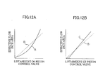
- the lift amount of the piston control valve 60 becomes larger and the opening area of the fuel flow path 57 becomes larger. Consequently, the pressure in the cylinder 56 rapidly increases, and thus the displacement speed of the piston 58 becomes faster, and a steep rise in pressure can be obtained.
- the lift amount of the piston control valve 60 becomes smaller and the opening area of the fuel flow path 57 becomes smaller. Consequently, pressure in the cylinder 56 increases gradually, and thus the displacement speed of the piston 58 becomes slower, and a gradual rise in pressure can be obtained.
- a fuel injection can be performed at the optimum injection rate when the needle valve 48 is opened and the fuel injection is performed.
- the structure is set to carry out position control (driving) of the piston control valve 60 using a PZT actuator, a super-magnetostrictive element or the like, lifting speed of the piston control valve 60 can be freely changed, and positional control can be carried out such that movement (lifting) of the piston control valve 60 stops partway through (at an intermediate position). Therefore, it is possible to arbitrarily specify a speed of change of the opening area of the fuel flow path 57 of the cylinder 56; that is, a speed of change of the inflow amount of fuel into the cylinder 56; that is, the speed of pressure intensification of the fuel that is sent to the fuel injection nozzle 34; that is, the injection rate of the fuel that is injected from the fuel injection nozzle 34.
- Figures 5 to 7 processes for specifying an injection rate by changing the area of the fuel flow path 57 of the cylinder 56 by the piston control valve 60, in the case in which the multiple injection with the fuel injection pattern shown in the aforementioned Figure 4 is implemented, is shown in schematic graphs.
- Figure 5 shows a pattern of changing the pressure intensification rate after completion of the boot injection period ( ⁇ 1)
- Figure 6 shows a pattern of changing the pressure intensification rate immediately before reaching the maximum injection pressure ( ⁇ 2)
- Figure 7 shows a pattern of changing the pressure reduction rate at the time of completion of the main injection ( ⁇ 3).
- the injection rate of the fuel that is injected from the fuel injection nozzle 34 can be arbitrarily specified (changed) by controlling inflow amounts of liquid fuel (by regulating movement amounts and movement periods (timings) of the piston control valve 60), by changing the area of the fuel flow path 57 to the cylinder 56 (the practical opening area of the flow path) with the piston control valve 60 (a degree of freedom of fuel injection patterns based on injection rates of the fuel is expanded).
- this fuel injection device 30 is a structure which changes the area of the fuel flow path 57 of the cylinder 56 by the piston control valve 60, changes inflow amounts of the fuel into the cylinder 56, and changes the movement speed (displacement speed) of the piston 58. Therefore, even in a case in which a maximum injection pressure is temporarily low, the rate of increase of the injection pressure can be set higher.
- control of rates of increase and rates of decrease of the injection pressure and control of pressure is similarly possible for the after-injection, by changing and controlling the fuel flow path area of the cylinder 56 with the piston control valve 60.
- an amount of an after-injection is usually extremely small in comparison with an amount of a main injection.
- a fuel amount for one cycle may be 1 to 2 cubic millimeters.
- lifting of the needle valve 48 of the fuel injection nozzle 34 may be what is known as a short-choke period, and it is difficult to clearly discriminate whether it is possible to change rates of increase and rates of decrease of injection pressure.
- the amount of the after-injection is more than or equal to 5 % of the main injection amount, this case is commonly known as a split injection.
- a split injection similarly to a time of main injection, control of rates of increase, rates of decrease, and maximum injection pressure of the injection pressure is possible, by the aforementioned opening area control.
- the injection rate of the fuel that is injected from the fuel injection nozzle 34 can be arbitrarily specified (changed) by controlling inflow amounts of the liquid fuel by changing the opening area of the fuel flow path 57 to the cylinder 56 with the piston control valve 60 (the degree of freedom of fuel injection patterns based on injection rates of the fuel is expanded).
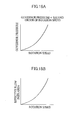
- a control valve with this flat seat form is a structure which regulates the cross-sectional area at the valve seat portion by controlling a lift amount (movement amount) of the valve ("seat portion area control").
- the protrusion 61 changes the area of the fuel flow path 57 in accordance with movement of the piston control valve 60. That is, the protrusion 61 is provided at the piston control valve 60 to be present in the fuel flow path 57 (the orifice), and is a structure which possesses the "fuel flow path area variability function", which changes the area of the fuel flow path 57 by the position of the protrusion 61 being changed in accordance with the movement amount (lift amount) of this piston control valve 60 ("orifice control").
- the cross-sectional area at the valve seat portion changes linearly in accordance with lift amounts (movement amounts) of the valve.
- the fuel injection device 30 relating to this first embodiment; by variously suitably specifying the form of the aforementioned protrusion 61, changes in the area of the fuel flow path 57 in accordance with movement amounts (lift amounts) of the piston control valve 60 can be freely specified.
- the injection control valve 52 is operated with, for example, a timing T 1 at times of lower speed, as shown by line A in Figure 13D, a fuel injection in which the injection rate of an initial period is lowered can be performed, and NOx and noise can be lowered. Further, if the injection control valve 52 is operated with, for example, a timing T 2 at times of high speed, times of high loading and the like, as shown by line A in Figure 13E, injection with an excessive injection period can be suppressed, and higher power output can be anticipated.
- fuel can be injected by a very high injection pressure which is significantly higher in comparison to convention, and favorable combustion and exhaust characteristics can be realized without a maximum injection pressure being determined principally by the fuel pressure of the pressure accumulator 32.
- a protrusion 72 which serves as the flow amount-changing means, is provided at a distal end portion of the piston control valve 60.
- This protrusion 72 is set to a two-step stepped form, and is a structure which can change the practical opening area of the fuel flow path 57 of the cylinder 56 in accordance with movement of the piston control valve 60.
- inflow amounts of the liquid fuel that is flowed into the cylinder 56 by the piston control valve 60 can be controlled.
- a rate of rise of the fuel pressure downstream of the pressure intensifier 54 can be set to a characteristic which increases with time. Therefore, similarly to the fuel injection device 30 relating to the first embodiment described above, it is possible to arbitrarily specify injection rates of the fuel that is injected from the fuel injection nozzle 34, and similar effects to the fuel injection device 30 relating to the first embodiment are implemented.
- the piston control valve 60 In the fuel injection device 80, concerning the piston control valve 60, it is provided to correspond to the piston 58 of the small bore side of the pressure intensifier 54, the piston 58 is moved by flowing out liquid fuel in the cylinder 56, and this is a structure which can obtain an increase of fuel pressure at the downstream side relative to the pressure-blocking valve 40.
- the piston control valve 60 it is a structure which arbitrarily specifies (changes) injection rates of the fuel that is injected from the fuel injection nozzle 34 by controlling inflow amounts of the liquid fuel, by changing the practical opening area of the fuel flow path 57 to the cylinder 56.
- the fuel injection device 80 concerning the piston control valve 60, it is structured so as to control outflow amounts of liquid fuel from the cylinder 56, by changing the opening area of a fuel flow path of the cylinder 56 (an outflow path), and is thus a structure which can arbitrarily specify (change) injection rates of the fuel that is injected from the fuel injection nozzle 34.
- a fixed orifice 92 and a movable orifice 94 are provided to serve as the flow amount-changing means.
- This fixed orifice 92 communicates with a fuel chamber 63 of the piston control valve 60.
- the movable orifice 94 is provided to overlap and communicate with an outer periphery of the fixed orifice 92, and moreover, is a structure which can change the degree of overlap with the fixed orifice 92 by moving.
- the movable orifice 94 is connected to an engine governor 96, which serves as moving means, and is structured such that fuel pressure with a second power of the engine rotation speed is effected for moving the movable orifice 94.
- the movable orifice 94 when fuel is to be injected, the movable orifice 94, at which the fuel pressure of the second power of the engine rotation speed is effected by the engine governor 96, is moved.
- the degree of overlap of the movable orifice 94 with the fixed orifice 92 is changed, and a practical opening area of this orifice is changed.
- the movement amount of the movable orifice 94 is roughly proportional to the fuel pressure that acts, that is, to the second power of the engine rotation speed. Therefore, the higher the engine rotation speed, the greater the degree of overlap of the movable orifice 94 with the fixed orifice 92 becomes, and the larger the effective opening area of the liquid fuel that flows into the fuel chamber 63 of the piston control valve 60 becomes. Thus, the pressure of the fuel that flows into the cylinder 56 (the rate of rise thereof) is changed by the piston control valve 60, and it is possible to change the movement speed of the piston 58.
- a relationship of effective opening area of this flow path in relation to, for example, engine rotation speed can be freely specified by suitably specifying shapes of the movable orifice 94 and the fixed orifice 92 (for example, rectangular forms, circular forms, trapezoid forms and the like) and changing numbers thereof.
- the shapes of the fixed orifice 92 and movable orifice 94, and movement speed and the like of the movable orifice 94 are specified by the engine governor 96 and the like in accordance with an optimum injection rate of the fuel that is injected from the fuel injection nozzle 34 (for example, an optimum injection rate of a pilot injection, a main injection or the like in accordance with engine rotation speed, loading conditions and the like), a fuel injection can be performed at the optimum injection rate when the needle valve 48 is opened and the fuel injection is performed. Therefore, fuel injection patterns can be realized with an extremely high degree of freedom.
- the fuel injection device 90 similarly to the fuel injection device 30 relating to the first embodiment described above, it is possible to arbitrarily specify injection rates of the fuel that is injected from the fuel injection nozzle 34, and similar effects to the fuel injection device 30 relating to the first embodiment are implemented.
- a pressure regulator 102 which serves as the flow amount-changing means, is provided at the fuel line 64 from the pressure accumulator 32, at which the piston control valve 60 is provided.
- the fuel injection device 100 similarly to the fuel injection device 30 relating to the first embodiment described above, it is possible to arbitrarily specify injection rates of the fuel that is injected from the fuel injection nozzle 34, and similar effects to the fuel injection device 30 relating to the first embodiment are implemented.
- this is not limited to being a structure in which the pressure regulator 102 is provided at the fuel line 64 from the pressure accumulator 32 and which changes inflow pressure of the fuel to the cylinder 56 as described above, and can be a structure in which this pressure regulator 102 is provided to correspond to the piston 58 of the small bore side of the pressure intensifier 54 (provided at a fuel outflow path from the cylinder 56) and which changes outflow pressure of liquid fuel that is flowed out from in the cylinder 56.
- a residual pressure regulation valve 112 is provided to serve as residual pressure-regulating means.
- This residual pressure regulation valve 112 is connected to the cylinder 56 of the large-bore piston 58 side of the pressure intensifier 54, via an orifice 114, and can regulate pressure in the cylinder 56 (the large-bore piston 58 side) to a predetermined pressure at a time of non-operation of the piston control valve 60.
- the pressure in the cylinder 56, of the large-bore piston 58 side of the pressure intensifier 54 can be maintained at the predetermined pressure by the residual pressure regulation valve 112, rather than decreasing to atmospheric pressure. Therefore, (because a residual pressure is conserved), corrosion of members caused by cavitation that occurs at the valve seat portion of the piston control valve 60 can be prevented, and reliability and durability are greatly improved.
- the fuel injection device 110 relating to this sixth embodiment is a structure in which the residual pressure regulation valve 112 is connected to the cylinder 56 via the orifice 114 (a structure in which the residual pressure regulation valve 112 is arranged at a downstream side of the orifice 114), but is not limited to this, and may be a structure in which the residual pressure regulation valve 112 is arranged at an upstream side of the orifice 114.
- the fuel injection device 110 relating to this sixth embodiment is a structure in which the piston control valve 60 is a two-way valve-type structure and the residual pressure regulation valve 112 is provided independently from the piston control valve 60, but is not limited to this, and may be a structure in which the residual pressure regulation valve 112 is integrated with the piston control valve 60, that is, the piston control valve 60 being a three-way valve-type structure having a function as a residual pressure regulation valve.
- This fuel injection device 120 is a structure which is basically similar to the fuel injection device 80 relating to the third embodiment described above ( Figure 16), but is a structure in which an orifice 122 and a residual pressure regulation valve 124 are provided between the cylinder 56 of the pressure intensifier 54 and the piston control valve 60.
- the piston control valve 60 moves the piston 58 by flowing out liquid fuel in the cylinder 56, can obtain an increase in fuel pressure at the downstream side relative to the pressure-blocking valve 40, and can regulate pressure in the cylinder 56 to the predetermined pressure with the residual pressure regulation valve 124 at times of non-operation of the piston control valve 60.
- the pressure in the cylinder 56 of the pressure intensifier 54 can be maintained at the predetermined pressure by the residual pressure regulation valve 124, rather than decreasing to atmospheric pressure. Therefore (because residual pressure is conserved), corrosion of members caused by cavitation can be prevented, and reliability and durability are greatly improved.
- the fuel injection device 120 relating to this seventh embodiment is a structure in which the residual pressure regulation valve 124 is provided between the cylinder 56 of the pressure intensifier 54 and the piston control valve 60 (a structure in which the residual pressure regulation valve 124 is arranged at an upstream side of the piston control valve 60), but is not limited to this, and may be a structure in which the residual pressure regulation valve 124 is arranged at a downstream side of the piston control valve 60.
- the fuel injection device 120 relating to this seventh embodiment is a structure in which the residual pressure regulation valve 124 is connected to the cylinder 56 via the orifice 122 (a structure in which the residual pressure regulation valve 124 is arranged at a downstream side of the orifice 122), but is not limited to this, and may be a structure in which the residual pressure regulation valve 124 is arranged at an upstream side of the orifice 122.
- the fuel injection device 120 relating to this seventh embodiment is a structure in which the piston control valve 60 is a two-way valve-type structure and the residual pressure regulation valve 124 is provided independently from the piston control valve 60, but is not limited to this, and may be a structure in which the residual pressure regulation valve 124 is integrated with the piston control valve 60, that is, the piston control valve 60 being a three-way valve-type structure having a function as a residual pressure regulation valve.
- resupplying means is provided for supplying fuel, which has been discharged from in the cylinder 56 in accordance with the piston control valve 60 closing and the piston 58 of the pressure intensifier 54 being moved to its original position again, to the fuel pressurization pump 38 again, in preparation for a next fuel injection.
- a medium-pressure common rail 132 is arranged at downstream of the fuel pressurization pump 38, and this is a structure at which a medium-pressure supply pump 136 and a feed pump 138 connect from a tank 134 to this medium-pressure common rail 132. Further, a pressure regulation valve 140 is provided at the medium-pressure common rail 132. Further, a residual pressure regulation valve 142, which is connected to the cylinder 56 of the pressure intensifier 54 via an orifice 143, is a structure which is connected to the medium-pressure common rail 132. Thus, fuel that is discharged via the residual pressure regulation valve 142 is returned to the medium-pressure common rail 132.
- pressure of the medium-pressure common rail 132 can be maintained at a predetermined pressure by providing a valve with a mechanical structure like the pressure regulation valve 140 at the medium-pressure common rail 132. If this is structured such that pressure of the medium-pressure common rail 132 can be appropriately variable relative to the pressure accumulator (common rail) 32 by implementing, for example, electronic control, residual pressure in the cylinder 56 of the pressure intensifier 54 can be optimally regulated, and efficiency of the injection system can be raised even further.
- pulsation between inside the cylinder 56 of the pressure intensifier 54 and the medium-pressure common rail 132 can be effectively damped by the residual pressure regulation valve 142 having been provided.
- structuring to omit the residual pressure regulation valve 142 is also possible.
- the residual pressure regulation valve 142 is not limited to a thing with a mechanical structure as described above, and may be structured as an electrically movable control valve so as to control pressure in the cylinder 56 of the pressure intensifier 54 (or a pressure difference between in the cylinder 56 and the medium-pressure common rail 132).
- pressure in the cylinder 56 of the pressure intensifier 54 can be controlled in accordance with the pressure of the pressure accumulator (common rail) 32, and efficiency of the injection system can be raised even further.
- the residual pressure regulation valve 142 is shown as being arranged at each respective injector of the engine, but is not limited to this, and may be a structure at which piping (pipelines) from the cylinder 56 of the pressure intensifier 54 of each respective injector are gathered, and the single residual pressure regulation valve 142 is arranged thereat. Consequently, a number of components can be reduced, and a reduction of costs can be anticipated.
- the fuel injection device 130 relating to the eighth embodiment described above is a structure in which the piston control valve 60 and the residual pressure regulation valve 142 are provided to correspond with the piston 58 of the large-bore side of the pressure intensifier 54, but is not limited to this, and may be a structure in which this piston control valve 60 and residual pressure regulation valve 142 are provided to correspond with the piston 58 of the small bore side of the pressure intensifier 54, like the fuel injection device 120 relating to the seventh embodiment shown in Figure 21, the piston 58 is moved by the liquid fuel in the cylinder 56 being flowed out, and the high-pressure fuel that has been discharged from the cylinder 56 is returned to the medium-pressure common rail 132.
- This fuel injection device 150 is a structure basically similar to the fuel injection device 130 relating to the eighth embodiment described above, but is a structure in which a supply pump 152, which is connected to the feed pump 138, is connected to the pressure accumulator (common rail) 32 just as it is.
- the supply pump 152 is a structure which pressurizes low-pressure fuel from the tank 134 (the feed pump 138) to high-pressure fuel, and supplies it to the pressure accumulator (common rail) 32 just as it is, without passing through the medium-pressure common rail 132.
- a fuel injection device relating to the present invention can be utilized, for example, at an internal combustion engine such as a diesel engine or the like which is mounted at a vehicle and injects pumped fuel into a cylinder for driving.
- an internal combustion engine such as a diesel engine or the like which is mounted at a vehicle and injects pumped fuel into a cylinder for driving.
Landscapes
- Engineering & Computer Science (AREA)
- Chemical & Material Sciences (AREA)
- Combustion & Propulsion (AREA)
- Mechanical Engineering (AREA)
- General Engineering & Computer Science (AREA)
- Physics & Mathematics (AREA)
- Electromagnetism (AREA)
- Fluid Mechanics (AREA)
- Fuel-Injection Apparatus (AREA)
Abstract
Description
Claims (8)
- A fuel injection device characterized by comprising:wherein flow amount-changing means capable of changing flow amounts of the fuel that is flowed into the cylinder or flowed out by the piston control valve is provided.a pressure accumulator communicated with a fuel pool in a fuel injection nozzle via a main fuel line, which accumulates pressure to set liquid fuel, which is pumped from a fuel pressurization pump, to a predetermined pressure;a pressure-blocking valve provided partway along the main fuel line that communicates the fuel injection nozzle with the pressure accumulator, which blocks outflow of pressurized fuel from the fuel injection nozzle side toward the pressure accumulator side;a fuel chamber for injection control which communicates at a downstream side, relative to the pressure-blocking valve, of the main fuel line that communicates the fuel injection nozzle with the pressure accumulator;an injection control valve provided at the fuel chamber for injection control, which obtains closure of a needle valve in the fuel injection nozzle by effecting liquid fuel pressure at the fuel chamber for injection control, and opens the needle valve and obtains performance of fuel injection by removing liquid fuel of the fuel chamber for injection control;a pressure intensifier having a cylinder and a piston, which communicates with the fuel chamber for injection control at the downstream side, relative to the pressure-blocking valve, of the main fuel line that communicates the fuel injection nozzle with the pressure accumulator; anda piston control valve which moves the piston of the pressure intensifier by flowing in fuel from the pressure accumulator to the cylinder or by flowing out fuel in the cylinder, and obtains an increase of fuel pressure of the downstream side relative to the pressure-blocking valve,
- The fuel injection device recited in claim 1, characterized by the flow amount-changing means being provided at the piston control valve and being a protrusion which changes an area of the fuel flow path of the cylinder in accordance with movement of the piston control valve.
- The fuel injection device recited in claim 1, characterized by the flow amount-changing means having: a fixed orifice which communicates with a fuel chamber of the piston control valve; a movable orifice which overlaps and communicates with the fixed orifice, and changes a degree of overlap with the fixed orifice by moving; and moving means which moves the movable orifice.
- The fuel injection device recited in claim 1, characterized by the flow amount-changing means being a pressure regulator which is provided at an inflow path of fuel into the cylinder or an outflow path of fuel from the cylinder.
- The fuel injection device recited in claim 1, characterized by residual pressure-regulating means, which regulates pressure in the cylinder to a predetermined pressure at a time of non-operation of the piston control valve, being provided.
- The fuel injection device recited in claim 1, characterized by resupplying means for again supplying fuel, which has been discharged from in the cylinder in accordance with movement of the piston at a time of operation of the piston control valve, to the fuel pressurization pump being provided.
- A fuel injection device characterized by comprising:wherein residual pressure-regulating means which regulates pressure in the cylinder to a predetermined pressure at a time of non-operation of the piston control valve is provided.a pressure accumulator communicated with a fuel pool in a fuel injection nozzle via a main fuel line, which accumulates pressure to set liquid fuel, which is pumped from a fuel pressurization pump, to a predetermined pressure;a pressure-blocking valve provided partway along the main fuel line that communicates the fuel injection nozzle with the pressure accumulator, which blocks outflow of pressurized fuel from the fuel injection nozzle side toward the pressure accumulator side;a fuel chamber for injection control which communicates at a downstream side, relative to the pressure-blocking valve, of the main fuel line that communicates the fuel injection nozzle with the pressure accumulator;an injection control valve provided at the fuel chamber for injection control, which obtains closure of a needle valve in the fuel injection nozzle by effecting fuel pressure at the fuel chamber for injection control, and opens the needle valve and obtains performance of fuel injection by removing liquid fuel of the fuel chamber for injection control;a pressure intensifier having a cylinder and a piston, which communicates with the fuel chamber for injection control at the downstream side, relative to the pressure-blocking valve, of the main fuel line that communicates the fuel injection nozzle with the pressure accumulator; anda piston control valve which moves the piston of the pressure intensifier by flowing in fuel from the pressure accumulator to the cylinder or by flowing out fuel in the cylinder, and obtains an increase of fuel pressure of the downstream side relative to the pressure-blocking valve,
- The fuel injection device recited in claim 7, characterized by resupplying means for again supplying fuel, which has been discharged from in the cylinder in accordance with movement of the piston at a time of operation of the piston control valve, to the fuel pressurization pump being provided.
Priority Applications (2)
| Application Number | Priority Date | Filing Date | Title |
|---|---|---|---|
| EP07103705A EP1790848B1 (en) | 2002-07-11 | 2003-07-11 | Fuel injection device |
| EP07103702A EP1790847B1 (en) | 2002-07-11 | 2003-07-11 | Fuel injection device |
Applications Claiming Priority (3)
| Application Number | Priority Date | Filing Date | Title |
|---|---|---|---|
| JP2002203203 | 2002-07-11 | ||
| JP2002203203A JP4007103B2 (en) | 2002-07-11 | 2002-07-11 | Fuel injection device |
| PCT/JP2003/008856 WO2004007947A1 (en) | 2002-07-11 | 2003-07-11 | Fuel injection apparatus |
Related Child Applications (2)
| Application Number | Title | Priority Date | Filing Date |
|---|---|---|---|
| EP07103705A Division EP1790848B1 (en) | 2002-07-11 | 2003-07-11 | Fuel injection device |
| EP07103702A Division EP1790847B1 (en) | 2002-07-11 | 2003-07-11 | Fuel injection device |
Publications (3)
| Publication Number | Publication Date |
|---|---|
| EP1522718A1 true EP1522718A1 (en) | 2005-04-13 |
| EP1522718A4 EP1522718A4 (en) | 2005-10-12 |
| EP1522718B1 EP1522718B1 (en) | 2009-09-23 |
Family
ID=30112666
Family Applications (3)
| Application Number | Title | Priority Date | Filing Date |
|---|---|---|---|
| EP03741361A Expired - Lifetime EP1522718B1 (en) | 2002-07-11 | 2003-07-11 | Fuel injection apparatus |
| EP07103705A Expired - Lifetime EP1790848B1 (en) | 2002-07-11 | 2003-07-11 | Fuel injection device |
| EP07103702A Expired - Lifetime EP1790847B1 (en) | 2002-07-11 | 2003-07-11 | Fuel injection device |
Family Applications After (2)
| Application Number | Title | Priority Date | Filing Date |
|---|---|---|---|
| EP07103705A Expired - Lifetime EP1790848B1 (en) | 2002-07-11 | 2003-07-11 | Fuel injection device |
| EP07103702A Expired - Lifetime EP1790847B1 (en) | 2002-07-11 | 2003-07-11 | Fuel injection device |
Country Status (6)
| Country | Link |
|---|---|
| US (1) | US6854446B2 (en) |
| EP (3) | EP1522718B1 (en) |
| JP (1) | JP4007103B2 (en) |
| DE (3) | DE60335223D1 (en) |
| ES (3) | ES2346577T3 (en) |
| WO (1) | WO2004007947A1 (en) |
Cited By (1)
| Publication number | Priority date | Publication date | Assignee | Title |
|---|---|---|---|---|
| EP1598551A1 (en) * | 2004-05-18 | 2005-11-23 | Robert Bosch Gmbh | Fuel injection device |
Families Citing this family (24)
| Publication number | Priority date | Publication date | Assignee | Title |
|---|---|---|---|---|
| JP4088600B2 (en) | 2004-03-01 | 2008-05-21 | トヨタ自動車株式会社 | Correction method for booster fuel injection system |
| JP2005315195A (en) | 2004-04-30 | 2005-11-10 | Toyota Motor Corp | Fuel injection control method for pressure-increasing common rail fuel injection device |
| JP4196895B2 (en) * | 2004-07-12 | 2008-12-17 | 株式会社デンソー | Fuel injection device |
| JP4003770B2 (en) | 2004-10-01 | 2007-11-07 | トヨタ自動車株式会社 | Fuel injection device |
| EP1657422A1 (en) | 2004-11-12 | 2006-05-17 | C.R.F. Societa' Consortile per Azioni | A method for controlling fuel injection in an internal combustion engine |
| DE102004057610A1 (en) * | 2004-11-29 | 2006-06-01 | Fev Motorentechnik Gmbh | Fuel injection method for e.g. piston internal combustion engine, involves closing and opening injection nozzle by pressure in pressure chamber under movement of locking piece that acts on nozzle by hydraulically-controlled pressure change |
| EP1836385B1 (en) * | 2004-12-03 | 2010-12-29 | Ganser-Hydromag AG | Fuel injection valve with pressure gain |
| JP2006274981A (en) * | 2005-03-30 | 2006-10-12 | Mitsubishi Fuso Truck & Bus Corp | Diesel engine control device |
| EP1717434A1 (en) * | 2005-04-28 | 2006-11-02 | Delphi Technologies, Inc. | Improvements relating to fuel injection systems |
| JP2007255307A (en) * | 2006-03-23 | 2007-10-04 | Mitsubishi Fuso Truck & Bus Corp | Fail-safe device of boosting common rail type fuel injector |
| JP2007255306A (en) * | 2006-03-23 | 2007-10-04 | Mitsubishi Fuso Truck & Bus Corp | Fail-safe device of boosting common rail type fuel injector |
| JP4640279B2 (en) * | 2006-07-17 | 2011-03-02 | 株式会社デンソー | Fuel injection control device for internal combustion engine |
| JP2008169817A (en) * | 2007-01-15 | 2008-07-24 | Denso Corp | Fuel injection valve, and adjusting method of injection characteristics of fuel injection valve |
| DE102007004745A1 (en) * | 2007-01-31 | 2008-08-14 | Iav Gmbh Ingenieurgesellschaft Auto Und Verkehr | Fuel injection system for internal combustion engine, has high pressure accumulator chamber that branches in supply line, which is continuously connected with pressure intensifier working chamber of pressure transmission unit |
| US8082902B2 (en) * | 2007-10-19 | 2011-12-27 | Caterpillar Inc. | Piezo intensifier fuel injector and engine using same |
| JP5237054B2 (en) * | 2008-11-07 | 2013-07-17 | 三菱重工業株式会社 | Control valve structure of accumulator fuel injector |
| JP5333918B2 (en) * | 2009-03-25 | 2013-11-06 | いすゞ自動車株式会社 | Fuel injection device |
| US20120199101A1 (en) * | 2011-02-07 | 2012-08-09 | Caterpillar Inc. | Pressure recovery system for low leakage cam assisted common rail fuel system, fuel injector and operating method therefor |
| EP2508746A1 (en) * | 2011-04-04 | 2012-10-10 | Caterpillar Motoren GmbH & Co. KG | A method for controlling an injection rate of a common rail fuel injector, a common rail fuel injection system and a fuel injector |
| DE102012204107A1 (en) | 2012-03-15 | 2013-09-19 | Robert Bosch Gmbh | metering |
| US10094324B2 (en) * | 2013-05-30 | 2018-10-09 | General Electric Company | System and method of operating an internal combustion engine |
| JP6269442B2 (en) * | 2014-10-30 | 2018-01-31 | トヨタ自動車株式会社 | Internal combustion engine |
| EP3550136A4 (en) * | 2016-12-02 | 2020-07-29 | Meiji University | FUEL INJECTION DEVICE |
| CN112343745A (en) * | 2020-10-21 | 2021-02-09 | 潍柴动力股份有限公司 | A fuel system and its control method |
Family Cites Families (14)
| Publication number | Priority date | Publication date | Assignee | Title |
|---|---|---|---|---|
| DE2803049A1 (en) | 1978-01-25 | 1979-08-09 | Bosch Gmbh Robert | PUMP NOZZLE FOR COMBUSTION MACHINES |
| JPS5637090Y2 (en) | 1980-02-21 | 1981-08-31 | ||
| JPS6039489Y2 (en) | 1981-05-28 | 1985-11-26 | ヤンマーディーゼル株式会社 | Pump nozzle for internal combustion engine |
| JPS61149770U (en) | 1985-03-07 | 1986-09-16 | ||
| JP2885076B2 (en) | 1994-07-08 | 1999-04-19 | 三菱自動車工業株式会社 | Accumulator type fuel injection device |
| US5732679A (en) * | 1995-04-27 | 1998-03-31 | Isuzu Motors Limited | Accumulator-type fuel injection system |
| US5641121A (en) * | 1995-06-21 | 1997-06-24 | Servojet Products International | Conversion of non-accumulator-type hydraulic electronic unit injector to accumulator-type hydraulic electronic unit injector |
| DE19910970A1 (en) * | 1999-03-12 | 2000-09-28 | Bosch Gmbh Robert | Fuel injector |
| DE19939428A1 (en) | 1999-08-20 | 2001-03-01 | Bosch Gmbh Robert | Method and device for performing a fuel injection |
| JP2001323858A (en) | 2000-05-17 | 2001-11-22 | Bosch Automotive Systems Corp | Fuel injection device |
| DE10040526A1 (en) | 2000-08-18 | 2002-03-14 | Bosch Gmbh Robert | Fuel injection system |
| DE10063545C1 (en) | 2000-12-20 | 2002-08-01 | Bosch Gmbh Robert | Fuel injection system |
| JP3987298B2 (en) * | 2001-04-05 | 2007-10-03 | 三菱ふそうトラック・バス株式会社 | Accumulated fuel injection system |
| JP2002364484A (en) | 2001-06-04 | 2002-12-18 | Toyota Central Res & Dev Lab Inc | Fuel injection device |
-
2002
- 2002-07-11 US US10/484,104 patent/US6854446B2/en not_active Expired - Lifetime
- 2002-07-11 JP JP2002203203A patent/JP4007103B2/en not_active Expired - Fee Related
-
2003
- 2003-07-11 EP EP03741361A patent/EP1522718B1/en not_active Expired - Lifetime
- 2003-07-11 EP EP07103705A patent/EP1790848B1/en not_active Expired - Lifetime
- 2003-07-11 DE DE60335223T patent/DE60335223D1/en not_active Expired - Lifetime
- 2003-07-11 WO PCT/JP2003/008856 patent/WO2004007947A1/en not_active Ceased
- 2003-07-11 ES ES07103705T patent/ES2346577T3/en not_active Expired - Lifetime
- 2003-07-11 ES ES03741361T patent/ES2333788T3/en not_active Expired - Lifetime
- 2003-07-11 ES ES07103702T patent/ES2357256T3/en not_active Expired - Lifetime
- 2003-07-11 EP EP07103702A patent/EP1790847B1/en not_active Expired - Lifetime
- 2003-07-11 DE DE60329391T patent/DE60329391D1/en not_active Expired - Lifetime
- 2003-07-11 DE DE60332671T patent/DE60332671D1/en not_active Expired - Lifetime
Cited By (1)
| Publication number | Priority date | Publication date | Assignee | Title |
|---|---|---|---|---|
| EP1598551A1 (en) * | 2004-05-18 | 2005-11-23 | Robert Bosch Gmbh | Fuel injection device |
Also Published As
| Publication number | Publication date |
|---|---|
| DE60329391D1 (en) | 2009-11-05 |
| JP4007103B2 (en) | 2007-11-14 |
| EP1790847B1 (en) | 2010-12-01 |
| ES2333788T3 (en) | 2010-03-01 |
| ES2346577T3 (en) | 2010-10-18 |
| DE60335223D1 (en) | 2011-01-13 |
| EP1522718B1 (en) | 2009-09-23 |
| EP1790847A3 (en) | 2008-01-23 |
| EP1790847A2 (en) | 2007-05-30 |
| DE60332671D1 (en) | 2010-07-01 |
| EP1522718A4 (en) | 2005-10-12 |
| ES2357256T3 (en) | 2011-04-20 |
| EP1790848B1 (en) | 2010-05-19 |
| JP2004044493A (en) | 2004-02-12 |
| US20040237930A1 (en) | 2004-12-02 |
| US6854446B2 (en) | 2005-02-15 |
| EP1790848A3 (en) | 2007-12-26 |
| WO2004007947A1 (en) | 2004-01-22 |
| EP1790848A2 (en) | 2007-05-30 |
Similar Documents
| Publication | Publication Date | Title |
|---|---|---|
| US6854446B2 (en) | Fuel injection apparatus | |
| EP1522719B1 (en) | Fuel injection method in fuel injector | |
| EP2134953B1 (en) | Fuel injection valve for internal combustion engine | |
| JP4239995B2 (en) | Fuel injection device for internal combustion engine | |
| KR100580699B1 (en) | Dual Control of Common Rail System | |
| US8100345B2 (en) | Fuel injection device | |
| JP2005315195A (en) | Fuel injection control method for pressure-increasing common rail fuel injection device | |
| JP3932688B2 (en) | Fuel injection device for internal combustion engine | |
| JP3804421B2 (en) | Fuel injection device | |
| US7568634B2 (en) | Injection nozzle | |
| JP3846917B2 (en) | Fuel injection device | |
| US20020185112A1 (en) | Fuel injector with direct needle valve control | |
| JP2005536681A (en) | Fuel injection device | |
| JP4229059B2 (en) | Fuel injection device for internal combustion engine | |
| US20020174854A1 (en) | Fuel injector with direct needle valve control | |
| JP4256771B2 (en) | Fuel control method and apparatus for diesel engine | |
| US20130255637A1 (en) | Fuel injector | |
| JP3719049B2 (en) | Injector | |
| WO2013147078A1 (en) | Hydraulic-drive fuel injection device and internal combustion engine | |
| JP2005291092A (en) | Common rail fuel injection system | |
| KR20120140605A (en) | Injector for fuel injection system | |
| CN1756903A (en) | Fuel injection valves for internal combustion engines |
Legal Events
| Date | Code | Title | Description |
|---|---|---|---|
| PUAI | Public reference made under article 153(3) epc to a published international application that has entered the european phase |
Free format text: ORIGINAL CODE: 0009012 |
|
| 17P | Request for examination filed |
Effective date: 20040119 |
|
| AK | Designated contracting states |
Kind code of ref document: A1 Designated state(s): AT BE BG CH CY CZ DE DK EE ES FI FR GB GR HU IE IT LI LU MC NL PT RO SE SI SK TR |
|
| A4 | Supplementary search report drawn up and despatched |
Effective date: 20050829 |
|
| RIC1 | Information provided on ipc code assigned before grant |
Ipc: 7F 02M 59/36 B Ipc: 7F 02M 47/00 A Ipc: 7F 02M 59/10 B Ipc: 7F 02M 55/02 B Ipc: 7F 02M 45/04 B Ipc: 7F 02M 47/02 B Ipc: 7F 02M 57/02 B Ipc: 7F 02M 59/32 B |
|
| RBV | Designated contracting states (corrected) |
Designated state(s): AT BE BG CH CY DE ES FR GB IT LI |
|
| 17Q | First examination report despatched |
Effective date: 20060321 |
|
| GRAP | Despatch of communication of intention to grant a patent |
Free format text: ORIGINAL CODE: EPIDOSNIGR1 |
|
| GRAS | Grant fee paid |
Free format text: ORIGINAL CODE: EPIDOSNIGR3 |
|
| GRAA | (expected) grant |
Free format text: ORIGINAL CODE: 0009210 |
|
| AK | Designated contracting states |
Kind code of ref document: B1 Designated state(s): DE ES FR GB IT |
|
| REG | Reference to a national code |
Ref country code: GB Ref legal event code: FG4D |
|
| REF | Corresponds to: |
Ref document number: 60329391 Country of ref document: DE Date of ref document: 20091105 Kind code of ref document: P |
|
| REG | Reference to a national code |
Ref country code: ES Ref legal event code: FG2A Ref document number: 2333788 Country of ref document: ES Kind code of ref document: T3 |
|
| PLBE | No opposition filed within time limit |
Free format text: ORIGINAL CODE: 0009261 |
|
| STAA | Information on the status of an ep patent application or granted ep patent |
Free format text: STATUS: NO OPPOSITION FILED WITHIN TIME LIMIT |
|
| 26N | No opposition filed |
Effective date: 20100624 |
|
| REG | Reference to a national code |
Ref country code: GB Ref legal event code: 746 Effective date: 20130412 |
|
| REG | Reference to a national code |
Ref country code: DE Ref legal event code: R084 Ref document number: 60329391 Country of ref document: DE Effective date: 20130410 |
|
| REG | Reference to a national code |
Ref country code: FR Ref legal event code: PLFP Year of fee payment: 14 |
|
| REG | Reference to a national code |
Ref country code: FR Ref legal event code: PLFP Year of fee payment: 15 |
|
| REG | Reference to a national code |
Ref country code: FR Ref legal event code: PLFP Year of fee payment: 16 |
|
| PGFP | Annual fee paid to national office [announced via postgrant information from national office to epo] |
Ref country code: FR Payment date: 20190619 Year of fee payment: 17 |
|
| PGFP | Annual fee paid to national office [announced via postgrant information from national office to epo] |
Ref country code: DE Payment date: 20190625 Year of fee payment: 17 Ref country code: IT Payment date: 20190719 Year of fee payment: 17 Ref country code: ES Payment date: 20190802 Year of fee payment: 17 |
|
| PGFP | Annual fee paid to national office [announced via postgrant information from national office to epo] |
Ref country code: GB Payment date: 20190710 Year of fee payment: 17 |
|
| REG | Reference to a national code |
Ref country code: DE Ref legal event code: R119 Ref document number: 60329391 Country of ref document: DE |
|
| GBPC | Gb: european patent ceased through non-payment of renewal fee |
Effective date: 20200711 |
|
| PG25 | Lapsed in a contracting state [announced via postgrant information from national office to epo] |
Ref country code: GB Free format text: LAPSE BECAUSE OF NON-PAYMENT OF DUE FEES Effective date: 20200711 Ref country code: FR Free format text: LAPSE BECAUSE OF NON-PAYMENT OF DUE FEES Effective date: 20200731 |
|
| PG25 | Lapsed in a contracting state [announced via postgrant information from national office to epo] |
Ref country code: DE Free format text: LAPSE BECAUSE OF NON-PAYMENT OF DUE FEES Effective date: 20210202 |
|
| REG | Reference to a national code |
Ref country code: ES Ref legal event code: FD2A Effective date: 20211201 |
|
| PG25 | Lapsed in a contracting state [announced via postgrant information from national office to epo] |
Ref country code: ES Free format text: LAPSE BECAUSE OF NON-PAYMENT OF DUE FEES Effective date: 20200712 |
|
| PG25 | Lapsed in a contracting state [announced via postgrant information from national office to epo] |
Ref country code: IT Free format text: LAPSE BECAUSE OF NON-PAYMENT OF DUE FEES Effective date: 20200711 |