EP1522654A2 - Tool for filling joints - Google Patents
Tool for filling joints Download PDFInfo
- Publication number
- EP1522654A2 EP1522654A2 EP04017936A EP04017936A EP1522654A2 EP 1522654 A2 EP1522654 A2 EP 1522654A2 EP 04017936 A EP04017936 A EP 04017936A EP 04017936 A EP04017936 A EP 04017936A EP 1522654 A2 EP1522654 A2 EP 1522654A2
- Authority
- EP
- European Patent Office
- Prior art keywords
- tool
- bevels
- sharp
- cut edge
- edge
- Prior art date
- Legal status (The legal status is an assumption and is not a legal conclusion. Google has not performed a legal analysis and makes no representation as to the accuracy of the status listed.)
- Withdrawn
Links
Images


Classifications
-
- B—PERFORMING OPERATIONS; TRANSPORTING
- B05—SPRAYING OR ATOMISING IN GENERAL; APPLYING FLUENT MATERIALS TO SURFACES, IN GENERAL
- B05C—APPARATUS FOR APPLYING FLUENT MATERIALS TO SURFACES, IN GENERAL
- B05C17/00—Hand tools or apparatus using hand held tools, for applying liquids or other fluent materials to, for spreading applied liquids or other fluent materials on, or for partially removing applied liquids or other fluent materials from, surfaces
- B05C17/005—Hand tools or apparatus using hand held tools, for applying liquids or other fluent materials to, for spreading applied liquids or other fluent materials on, or for partially removing applied liquids or other fluent materials from, surfaces for discharging material from a reservoir or container located in or on the hand tool through an outlet orifice by pressure without using surface contacting members like pads or brushes
- B05C17/00503—Details of the outlet element
- B05C17/00516—Shape or geometry of the outlet orifice or the outlet element
-
- E—FIXED CONSTRUCTIONS
- E04—BUILDING
- E04F—FINISHING WORK ON BUILDINGS, e.g. STAIRS, FLOORS
- E04F21/00—Implements for finishing work on buildings
- E04F21/02—Implements for finishing work on buildings for applying plasticised masses to surfaces, e.g. plastering walls
- E04F21/06—Implements for applying plaster, insulating material, or the like
-
- E—FIXED CONSTRUCTIONS
- E04—BUILDING
- E04F—FINISHING WORK ON BUILDINGS, e.g. STAIRS, FLOORS
- E04F21/00—Implements for finishing work on buildings
- E04F21/165—Implements for finishing work on buildings for finishing joints, e.g. implements for raking or filling joints, jointers
-
- E—FIXED CONSTRUCTIONS
- E04—BUILDING
- E04F—FINISHING WORK ON BUILDINGS, e.g. STAIRS, FLOORS
- E04F21/00—Implements for finishing work on buildings
- E04F21/165—Implements for finishing work on buildings for finishing joints, e.g. implements for raking or filling joints, jointers
- E04F21/1652—Implements for finishing work on buildings for finishing joints, e.g. implements for raking or filling joints, jointers for smoothing and shaping joint compound to a desired contour
Definitions
- the present invention relates to a tool for grouting joints with at least an inlet opening for the joint material and at least one outlet opening for the Grout material, wherein the two openings are interconnected by a channel.
- the invention has for its object to provide a tool for grouting joints create, with the help of which, a simple and even grouting without big Material loss is possible.
- a tool of the type mentioned which thereby characterized in that the tool is at one end by two opposing ones Bevels roof-shaped bevelled, with the cut edge of the two Chamfers partly as a substantially sharp edge and partly as a rounding is trained.
- Preferred embodiments or further developments of the tool according to the invention are characterized in the subclaims.
- the tool at one end by two opposing ones Bevels roof-shaped beveled and the cutting edge of the two bevels partially formed as a substantially sharp edge and partly as a rounding can by applying the sharp-edged portion of the cut edge of the two bevels on the Groove, applying grout material through the outlet and guiding the tool in the direction of the sharp-edged portion of the cut edge of the two bevels one clean joint be laid without major loss of material, so no deduction of excess grout is needed.
- the outlet opening for the joint material between the sharp-edged and the rounded portion of the cut edge of the two bevels is preferably formed from the sharp-edged and the rounded portion of the cut edge of the two bevels.
- the two opposing bevels close an angle of about 10 to 170 °, preferably about 40 to 120 °, more preferably 90 °.
- the basic shape of the tool is arbitrary. However, it is preferred that the tool the Has the shape of a one-sided beveled cube or cuboid.
- the cut edge of the two chamfers can be substantially half as in essential sharp edge and be formed substantially as a rounding.
- the rounded portion of the cut edge of the two bevels lies in a depression. This will cause a lateral leakage of grout during the Laying a joint almost impossible, since the two bevels in this way also in the rounded area sealingly abut the joint.
- the inlet opening for the joint material optionally serves in cooperation with a part of the channel as a receptacle for a cartridge nozzle.
- the cartridge nozzle can be screwed on.
- the cartridge nozzle is attachable.
- the tool can be designed as a disposable article for one-time use.
- the tool has a supply line, in particular a supply pipe, for the joint material.
- the supply line can be one piece be connected to the main body of the tool.
- This supply pipe can be flexible or be rigid.
- the supply pipe forms an extension the connecting channel between the inlet opening for the joint material and the Outlet opening for the joint material.
- the inlet opening is in this case by the Input of the supply pipe formed.
- the tool according to the invention may e.g. of metal, wood, or other, essentially hard to be made of materials. Preferably, it consists essentially of hard plastic.
- the tool can be solid. The tool can also save material not massive, e.g. rugged, hollow, be formed.
- the tool can be produced by injection molding.
- the invention further relates to a method for producing a sealing joint, wherein the Tool according to the invention with the sharp-edged portion of the cutting edge of the two Bevels are applied to a joint to be executed, grout material through the Outlet opening is pressed and the tool towards the rounded area of the Cut edge of the two bevels is performed.
- this can be sprayed with soap suds and peeled off become. After renewed spraying of the joint can be smoothed with a finger.
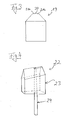
- Figure 1 shows a perspective view of an embodiment of a tool 1 according to the invention with a front side 2, a back 3, a square bottom surface 4 and two side surfaces 5a and 5b.
- the tool 1 shown has the shape of a beveled cuboid on one side and is made of hard plastic.
- the tool 1 is beveled roof-shaped at the top by two opposing bevels 6a, 6b, wherein the cut edge of the two bevels approximately half as a sharp edge 7 and about half is formed as a rounding 8.
- the tool 1 has an inlet opening 9 for the joint material, such as silicone, and an outlet opening 10 for the joint material.
- the two openings 9 and 10 are connected by the channel 11 with each other, which serves as a conduit for the joint material.
- the channel 11 may also serve in the region of the inlet opening 9 as a receptacle for example a cartridge nozzle.
- the channel 11 is cylindrical in the embodiment shown.
- the outlet opening 10 is located between the sharp edge 7 and the rounding 8.
- the two opposing bevels 6a and 6b enclose an angle of 90 °.
- the two cut edges 12a and 12b of the side surfaces 5a and 5b and the chamfers 6a and 6b do not run parallel to the bottom surface 4, but rise from the front side 2 to the back 3 towards.
- the two cut edges 12a and 12b run parallel to the cut edge of the two bevels 6a and 6b, ie to the sharp edges 7 and to the rounding 8, so that the roof-shaped bevel, consisting of the two bevels 6a and 6b, is inclined towards the front side 2.
- Figure 2 shows a slightly perspective side view of the tool according to the invention according to Figure 1 but with a conical channel 13 for the joint material and in use when grouting a joint.
- the chamfered tool 1 When the chamfered tool 1 is inserted into a groove formed at right-angled walls 14a and 14b, the two chamfers 6a and 6b close tightly in the region 15 of the sharp edge 7 with the abutting walls 14a and 14b from.
- a cavity 17 is formed in the shape of the joint to be formed, since the rounding 8 is slightly offset with respect to the sharp edge 7 in the direction of the bottom surface 4.
- the sides 18a and 18b of the resulting cavity are sealed by the two bevels 6a and 6b in the region 16 of the rounding 8.
- Figure 3 shows a rear view of a tool according to the invention, in which the Rounding 8 is located in a recess 20. This shows the two bevels in Region of the rounding 8 on its upper side in each case an edge 21a and 21b. Through this Edges are sealed the sides of the cavity 17 even better.
- FIG. 4 shows a slightly perspective side view of a tool according to the invention 22 with main body 23 and supply pipe 24, wherein the base body 23 and the Supply pipe 24 are integrally connected to each other.
- the basic body corresponds to this embodiment, the tool 1 of Figures 1 and 2, respectively.
- the supply pipe is in This embodiment is flexible.
- FIG. 5 shows a rear view of the tool 1 according to the invention during work with plugged cartridge nozzle 25 from the silicone into the channel 11 penetrates and through the Outlet opening 10 enters the cavity 17.
Abstract
Description
Die vorliegende Erfindung betrifft ein Werkzeug zum Ausfugen von Fugen mit mindestens einer Eintrittsöffnung für das Fugenmaterial und mindestens einer Austrittsöffnung für das Fugenmaterial, wobei die beiden Öffnungen durch einen Kanal miteinander verbunden sind.The present invention relates to a tool for grouting joints with at least an inlet opening for the joint material and at least one outlet opening for the Grout material, wherein the two openings are interconnected by a channel.
Das Verfugen von beispielsweise Raumecken, also von Fugen, die unter einem Winkel,
insbesondere rechten Winkel, aufeinanderstoßenden Wänden gebildet werden, wurde bisher
mit Hilfe von Kartuschen mit einfachen Aufschraubdüsen durchgeführt. Dabei wurde das
Verfugungsmaterial, wie beispielsweise Acryl, Silikon oder andere geeignete Dichtungsstoffe,
zum Austreten durch die Düse in die zu bearbeitende Fuge gebracht.
Ungeübten Personen ist es fast unmöglich mit dieser herkömmlichen Variante eine
fachmännische Fugennaht, d.h. eine gleichmäßige Verfugung ohne Ausrutscher und großem
Materialverlust zu verlegen.The grouting of, for example, room corners, ie joints, which are formed at an angle, in particular right angle, abutting walls, has hitherto been carried out with the aid of cartridges with simple screw-on nozzles. In this case, the jointing material, such as acrylic, silicone or other suitable sealants, was brought to exit through the nozzle in the joint to be processed.
Inexperienced persons, it is almost impossible with this conventional variant expert seam seam, ie to lay a uniform grouting without slipping and large material loss.
Der Erfindung liegt die Aufgabe zugrunde, ein Werkzeug zum Ausfugen von Fugen zu schaffen, mit Hilfe dessen ein einfaches und gleichmäßiges Verfugen ohne großen Materialverlust möglich ist.The invention has for its object to provide a tool for grouting joints create, with the help of which, a simple and even grouting without big Material loss is possible.
Diese Aufgabe wird gelöst durch ein Werkzeug der eingangs genannten Art, welches dadurch gekennzeichnet ist, dass das Werkzeug an einem Ende durch zwei sich gegenüberliegende Abschrägungen dachförmig abgeschrägt ist, wobei die Schnittkante der beiden Abschrägungen teilweise als im wesentlichen scharfe Kante und teilweise als Abrundung ausgebildet ist. Bevorzugte Aus- bzw. Weiterbildungen des erfindungsgemäßen Werkzeugs sind in den Unteransprüchen gekennzeichnet.This object is achieved by a tool of the type mentioned, which thereby characterized in that the tool is at one end by two opposing ones Bevels roof-shaped bevelled, with the cut edge of the two Chamfers partly as a substantially sharp edge and partly as a rounding is trained. Preferred embodiments or further developments of the tool according to the invention are characterized in the subclaims.
Durch die Tatsache, dass das Werkzeug an einem Ende durch zwei sich gegenüberliegende Abschrägungen dachförmig abgeschrägt ist und die Schnittkante der beiden Abschrägungen teilweise als im wesentlichen scharfe Kante und teilweise als Abrundung ausgebildet ist, kann durch Anlegen des scharfkantigen Bereichs der Schnittkante der beiden Abschrägungen an die Fuge, Ausbringen von Fugenmaterial durch die Austrittsöffnung und Führen des Werkzeugs in Richtung des scharfkantigen Bereichs der Schnittkante der beiden Abschrägungen eine saubere Fuge ohne großen Materialverlust verlegt werden, sodass kein Abziehen von überschüssiger Fugenmasse nötig ist.By the fact that the tool at one end by two opposing ones Bevels roof-shaped beveled and the cutting edge of the two bevels partially formed as a substantially sharp edge and partly as a rounding can by applying the sharp-edged portion of the cut edge of the two bevels on the Groove, applying grout material through the outlet and guiding the tool in the direction of the sharp-edged portion of the cut edge of the two bevels one clean joint be laid without major loss of material, so no deduction of excess grout is needed.
Vorzugsweise ist die Austrittsöffnung für das Fugenmaterial zwischen dem scharfkantigen und dem abgerundeten Bereich der Schnittkante der beiden Abschrägungen vorgesehen.Preferably, the outlet opening for the joint material between the sharp-edged and the rounded portion of the cut edge of the two bevels.
Mit Vorteil schließen die beiden sich gegenüberliegenden Abschrägungen einen Winkel von ca. 10 - 170°, vorzugsweise ca. 40 -120°, besonders bevorzugt 90° ein.Advantageously, the two opposing bevels close an angle of about 10 to 170 °, preferably about 40 to 120 °, more preferably 90 °.
Die Grundform des Werkzeuges ist beliebig. Es ist jedoch bevorzugt, dass das Werkzeug die Form eines einseitig abgeschrägten Würfels oder Quaders aufweist.The basic shape of the tool is arbitrary. However, it is preferred that the tool the Has the shape of a one-sided beveled cube or cuboid.
Die Schnittkante der beiden Abschrägungen kann im wesentlichen zur Hälfte als im wesentlichen scharfe Kante und im wesentlichen zur Hälfte als Abrundung ausgebildet sein.The cut edge of the two chamfers can be substantially half as in essential sharp edge and be formed substantially as a rounding.
Vorzugsweise liegt der abgerundete Bereich der Schnittkante der beiden Abschrägungen in einer Vertiefung. Dadurch wird ein seitliches Austreten von Fugenmaterial während dem Verlegen einer Fuge fast unmöglich, da die beiden Abschrägungen auf diese Weise auch im abgerundeten Bereich abdichtend an der Fuge anliegen.Preferably, the rounded portion of the cut edge of the two bevels lies in a depression. This will cause a lateral leakage of grout during the Laying a joint almost impossible, since the two bevels in this way also in the rounded area sealingly abut the joint.
Mit Vorteil dient die Eintrittsöffnung für das Fugenmaterial ggf. im Zusammenwirken mit
einem Teil des Kanals als Aufnahme für eine Kartuschendüse. Die Kartuschendüse kann
aufschraubbar sein. Vorzugsweise ist die Kartuschendüse aufsteckbar.
Das Werkzeug kann als Wegwerfartikel für den einmaligen Gebrauch ausgebildet sein.Advantageously, the inlet opening for the joint material optionally serves in cooperation with a part of the channel as a receptacle for a cartridge nozzle. The cartridge nozzle can be screwed on. Preferably, the cartridge nozzle is attachable.
The tool can be designed as a disposable article for one-time use.
Bei einer weiteren Ausbildungsform der Erfindung weist das Werkzeug eine Zuleitung, insbesondere ein Zuleitungsrohr, für das Fugenmaterial auf. Die Zuleitung kann einstückig mit dem Grundkörper des Werkzeugs verbunden sein. Dieses Zuleitungsrohr kann flexibel oder starr ausgebildet sein. Vorteilhafterweise bildet das Zuleitungsrohr eine Verlängerung des Verbindungskanals zwischen der Eintrittsöffnung für das Fugenmaterial und der Austrittsöffnung für das Fugenmaterial. Die Eintrittsöffnung wird in diesem Falle durch den Eingang des Zuleitungsrohres gebildet.In a further embodiment of the invention, the tool has a supply line, in particular a supply pipe, for the joint material. The supply line can be one piece be connected to the main body of the tool. This supply pipe can be flexible or be rigid. Advantageously, the supply pipe forms an extension the connecting channel between the inlet opening for the joint material and the Outlet opening for the joint material. The inlet opening is in this case by the Input of the supply pipe formed.
Das erfindungsgemäße Werkzeug kann z.B. aus Metall, Holz, oder anderen, im wesentlichen harten, Materialien gefertigt sein. Bevorzugt besteht es im wesentlichen aus Hartkunststoff. Das Werkzeug kann massiv ausgebildet sein. Um Material zu sparen kann das Werkzeug auch nicht massiv, z.B. zerklüftet, hohl, ausgebildet sein.The tool according to the invention may e.g. of metal, wood, or other, essentially hard to be made of materials. Preferably, it consists essentially of hard plastic. The tool can be solid. The tool can also save material not massive, e.g. rugged, hollow, be formed.
Mit Vorteil ist das Werkzeug im Spritzgussverfahren herstellbar.Advantageously, the tool can be produced by injection molding.
Bei einer bevorzugten Ausführungsform der Erfindung ist die dachförmige Abschrägung in Richtung des scharfkantigen Bereichs der Schnittkante der beiden Abschrägungen geneigt.In a preferred embodiment of the invention, the roof-shaped bevel in Direction of the sharp-edged portion of the cut edge of the two bevels inclined.
Die Erfindung betrifft ferner ein Verfahren zur Herstellung einer Dichtungsfuge, wobei das erfindungsgemäße Werkzeug mit dem scharfkantigen Bereich der Schnittkante der beiden Abschrägungen an eine auszufugende Fuge angelegt wird, Fugenmaterial durch die Austrittsöffnung gepresst wird und das Werkzeug in Richtung des abgerundeten Bereichs der Schnittkante der beiden Abschrägungen geführt wird.The invention further relates to a method for producing a sealing joint, wherein the Tool according to the invention with the sharp-edged portion of the cutting edge of the two Bevels are applied to a joint to be executed, grout material through the Outlet opening is pressed and the tool towards the rounded area of the Cut edge of the two bevels is performed.
Nach der Bildung der Fuge kann diese mit Seifenlauge eingesprüht werden und abgezogen werden. Nach nochmaligem Einsprühen der Fuge kann mit dem Finger nachgeglättet werden.After the formation of the joint, this can be sprayed with soap suds and peeled off become. After renewed spraying of the joint can be smoothed with a finger.
Weitere Merkmale der Erfindung ergeben sich aus der nachfolgenden Beschreibung von bevorzugten Ausführungsformen der Erfindung in Verbindung mit den Zeichnungen und den Unteransprüchen. Hierbei können die einzelnen Merkmale jeweils für sich allein oder in Kombination miteinander verwirklicht sein.Further features of the invention will become apparent from the following description of preferred embodiments of the invention in conjunction with the drawings and the Dependent claims. Here, the individual features can be used alone or in each case Combination be realized with each other.
In den Zeichnungen zeigen:
- Figur 1:
- eine perspektivische Darstellung einer Ausführungsform eines erfindungsgemäßen Werkzeugs
- Figur 2:
- eine leicht perspektivische Seitenansicht des erfindungsgemäßen Werkzeugs nach Figur 1 aber mit konischem Zuführungskanal und im Verfugungseinsatz
- Figur 3:
- eine Rückseitenansicht eines erfindungsgemäßen Werkzeugs mit Vertiefung
- Figur 4 :
- eine leicht perspektivische Seitenansicht eines erfindungsgemäßen Werkzeugs mit Zuleitungsrohr
- Figur 5:
- eine Rückseitenansicht eines erfindungsgemäßen Werkzeugs im Arbeitseinsatz
- FIG. 1:
- a perspective view of an embodiment of a tool according to the invention
- FIG. 2:
- a slightly perspective side view of the tool according to the invention according to Figure 1 but with a conical feed channel and in Verfugungseinsatz
- FIG. 3:
- a rear view of a tool according to the invention with recess
- FIG. 4:
- a slightly perspective side view of a tool according to the invention with supply pipe
- FIG. 5:
- a rear view of a tool according to the invention in the labor input
Figur 1 zeigt eine perspektivische Darstellung einer Ausführungsform eines
erfindungsgemäßen Werkzeugs 1 mit einer Vorderseite 2, einer Rückseite 3, einer
quadratischen Bodenfläche 4 und zwei Seitenflächen 5a und 5b. Das gezeigte Werkzeug 1
weist die Form eines auf einer Seite abgeschrägten Quaders auf und ist aus Hartkunststoff
gefertigt. Das Werkzeug 1 ist an der Oberseite durch zwei sich gegenüberliegende
Abschrägungen 6a, 6b dachförmig abgeschrägt, wobei die Schnittkante der beiden
Abschrägungen ca. zur Hälfte als scharfe Kante 7 und ca. zur Hälfte als Abrundung 8
ausgebildet ist. Zudem weist das Werkzeug 1 eine Eintrittsöffnung 9 für das Fugenmaterial,
wie beispielsweise Silikon, und eine Austrittsöffnung 10 für das Fugenmaterial auf. Die
beiden Öffnungen 9 und 10 sind durch den Kanal 11 mit einander verbunden, welcher als
Leitung für das Fugenmaterial dient. Der Kanal 11 kann im Bereich der Eintrittsöffnung 9
auch als Aufnahme für z.B. eine Kartuschendüse dienen. Der Kanal 11 ist in dem gezeigten
Ausführungsbeispiel zylindrisch ausgebildet. Die Austrittsöffnung 10 liegt zwischen der
scharfen Kante 7 und der Abrundung 8. Die beiden sich gegenüberliegenden Abschrägungen
6a und 6b schließen einen Winkel von 90° ein.
Die beiden Schnittkanten 12a und 12b der Seitenflächen 5a und 5b und der Abschrägungen 6a
und 6b verlaufen nicht parallel zur Bodenfläche 4, sondern steigen von der Vorderseite 2
ausgehend zur Rückseite 3 hin an. Die beiden Schnittkanten 12a und 12b
verlaufen hingegen parallel zur Schnittkante der beiden Abschrägungen 6a und 6b, also zur
scharfen Kanten 7 und zur Abrundung 8, sodass die dachförmige Abschrägung, bestehend aus
den beiden Abschrägungen 6a und 6b, zur Vorderseite 2 hin geneigt ist. Figure 1 shows a perspective view of an embodiment of a tool 1 according to the invention with a
The two
Figur 2 zeigt eine leicht perspektivische Seitenansicht des erfindungsgemäßen Werkzeugs
nach Figur 1 aber mit konischem Kanal 13 für das Fugenmaterial und im Einsatz beim
Verfugen einer Fuge.
Wird das Werkzeug 1 mit dem abgeschrägten Bereich in eine Fuge, die unter einem rechten
Winkel aufeinanderstoßenden Wänden 14a und 14b gebildet wird, eingesetzt, so schließen die
beiden Abschrägungen 6a und 6b im Bereich 15 der scharfen Kante 7 mit den
aufeinanderstoßenden Wänden 14a und 14b dicht ab. Im Bereich 16 der Abrundung 8 entsteht
jedoch ein Hohlraum 17 in der Form der zu bildenden Fuge, da die Abrundung 8 im Hinblick
auf die scharfe Kante 7 in Richtung der Bodenfläche 4 leicht versetzt ist. Die Seiten 18a und
18b des entstehenden Hohlraumes sind durch die beiden Abschrägungen 6a und 6b im
Bereich 16 der Abrundung 8 abgedichtet. Beim Führen des Werkzeugs 1 in Richtung der
scharfen Kante 7 entsteht so eine saubere Fuge (der Pfeil zeigt die Führungsrichtung des
Werkzeuges beim Verfugen).Figure 2 shows a slightly perspective side view of the tool according to the invention according to Figure 1 but with a conical channel 13 for the joint material and in use when grouting a joint.
When the chamfered tool 1 is inserted into a groove formed at right-angled walls 14a and 14b, the two chamfers 6a and 6b close tightly in the
Figur 3 zeigt eine Rückseitenansicht eines erfindungsgemäßen Werkzeugs, bei dem die
Abrundung 8 in einer Vertiefung 20 liegt. Dadurch weisen die beiden Abschrägungen im
Bereich der Abrundung 8 an ihrer Oberseite jeweils eine Kante 21a bzw. 21b auf. Durch diese
Kanten werden die Seiten des Hohlraumes 17 noch besser abgedichtet.Figure 3 shows a rear view of a tool according to the invention, in which the
Rounding 8 is located in a
Figur 4 zeigt eine leicht perspektivische Seitenansicht eines erfindungsgemäßen Werkzeugs
22 mit Grundkörper 23 und Zuleitungsrohr 24, wobei der Grundkörper 23 und das
Zuleitungsrohr 24 einstückig miteinander verbunden sind. Der Grundkörper entspricht in
diesem Ausführungsbeispiel dem Werkzeug 1 der Figuren 1 bzw. 2. Das Zuleitungsrohr ist in
diesem Ausführungsbeispiel flexibel ausgebildet.FIG. 4 shows a slightly perspective side view of a tool according to the
Figur 5 zeigt eine Rückseitenansicht des erfindungsgemäßen Werkzeugs 1 im Arbeitseinsatz
mit aufgesteckter Kartuschendüse 25 aus der Silikon in den Kanal 11 dringt und durch die
Austrittsöffnung 10 in den Hohlraum 17 gelangt.FIG. 5 shows a rear view of the tool 1 according to the invention during work
with plugged
Claims (13)
Applications Claiming Priority (4)
| Application Number | Priority Date | Filing Date | Title |
|---|---|---|---|
| DE10346696 | 2003-10-08 | ||
| DE10346696 | 2003-10-08 | ||
| DE20318048U DE20318048U1 (en) | 2003-11-21 | 2003-11-21 | Joint shaper attachable to a silicone or acrylate cartridge has a block-shaped body whose bottom edge is provided with shamfers and a rounded section incorporating a recess |
| DE20318048U | 2003-11-21 |
Publications (2)
| Publication Number | Publication Date |
|---|---|
| EP1522654A2 true EP1522654A2 (en) | 2005-04-13 |
| EP1522654A3 EP1522654A3 (en) | 2007-05-23 |
Family
ID=33491685
Family Applications (1)
| Application Number | Title | Priority Date | Filing Date |
|---|---|---|---|
| EP04017936A Withdrawn EP1522654A3 (en) | 2003-10-08 | 2004-07-29 | Tool for filling joints |
Country Status (2)
| Country | Link |
|---|---|
| EP (1) | EP1522654A3 (en) |
| DE (1) | DE202004011933U1 (en) |
Cited By (2)
| Publication number | Priority date | Publication date | Assignee | Title |
|---|---|---|---|---|
| GB2524508A (en) * | 2014-03-25 | 2015-09-30 | Eric Owen | Nozzle arrangement, cartridge for applicator gun, and method of forming bead of sealant or filler |
| EP2942109A1 (en) * | 2014-04-14 | 2015-11-11 | Rasim Begovic | Device for creating joints between angled components |
Citations (5)
| Publication number | Priority date | Publication date | Assignee | Title |
|---|---|---|---|---|
| US4798502A (en) * | 1985-06-18 | 1989-01-17 | Lily Corporation | Corner grouting nozzle |
| US5257486A (en) * | 1991-04-23 | 1993-11-02 | Adhesives Technology Corporation 1987 | Nozzle for injecting a sealant into a crack |
| EP1353024A2 (en) * | 2002-04-10 | 2003-10-15 | Nadine Veith | Tool for shaping plastic masses, in particular for forming raised profiles |
| DE20318048U1 (en) * | 2003-11-21 | 2004-03-25 | Hoffmann, Christian | Joint shaper attachable to a silicone or acrylate cartridge has a block-shaped body whose bottom edge is provided with shamfers and a rounded section incorporating a recess |
| DE202004002927U1 (en) * | 2004-02-23 | 2004-05-06 | Fetzer, Bernhard | Device for forming joints |
-
2004
- 2004-07-29 EP EP04017936A patent/EP1522654A3/en not_active Withdrawn
- 2004-07-29 DE DE202004011933U patent/DE202004011933U1/en not_active Expired - Lifetime
Patent Citations (5)
| Publication number | Priority date | Publication date | Assignee | Title |
|---|---|---|---|---|
| US4798502A (en) * | 1985-06-18 | 1989-01-17 | Lily Corporation | Corner grouting nozzle |
| US5257486A (en) * | 1991-04-23 | 1993-11-02 | Adhesives Technology Corporation 1987 | Nozzle for injecting a sealant into a crack |
| EP1353024A2 (en) * | 2002-04-10 | 2003-10-15 | Nadine Veith | Tool for shaping plastic masses, in particular for forming raised profiles |
| DE20318048U1 (en) * | 2003-11-21 | 2004-03-25 | Hoffmann, Christian | Joint shaper attachable to a silicone or acrylate cartridge has a block-shaped body whose bottom edge is provided with shamfers and a rounded section incorporating a recess |
| DE202004002927U1 (en) * | 2004-02-23 | 2004-05-06 | Fetzer, Bernhard | Device for forming joints |
Cited By (2)
| Publication number | Priority date | Publication date | Assignee | Title |
|---|---|---|---|---|
| GB2524508A (en) * | 2014-03-25 | 2015-09-30 | Eric Owen | Nozzle arrangement, cartridge for applicator gun, and method of forming bead of sealant or filler |
| EP2942109A1 (en) * | 2014-04-14 | 2015-11-11 | Rasim Begovic | Device for creating joints between angled components |
Also Published As
| Publication number | Publication date |
|---|---|
| EP1522654A3 (en) | 2007-05-23 |
| DE202004011933U1 (en) | 2004-11-18 |
Similar Documents
| Publication | Publication Date | Title |
|---|---|---|
| DE69817129T2 (en) | Device for removing sealing strands | |
| DE2426322A1 (en) | SPATULA | |
| WO2000012842A1 (en) | Hand-held device for removing joint fillers | |
| EP2740861B1 (en) | Device for applying, confining and smoothing joints that are manually filled with a plastic filling compound | |
| DE2819972A1 (en) | HOLDER BAG FOR A FASTENING ELEMENT IN AN OBJECT OF THERMOPLASTIC MATERIAL | |
| EP2942109B1 (en) | Device for creating joints between angled components | |
| CH616993A5 (en) | Tongue plate for a releaseable groove-and-tongue connection | |
| DE19847514B4 (en) | Two tools for processing, compaction, smoothing and finishing of all plastic grout | |
| EP3255222B1 (en) | Device and system for processing a jointing material | |
| DE202014001032U1 (en) | Nozzle for applying pasty substances | |
| EP2512851A1 (en) | Butt joint between ends of sealing strips or of a sealing strip | |
| DE2646007A1 (en) | ANCHORING DOWEL | |
| EP1522654A2 (en) | Tool for filling joints | |
| DE10142560A1 (en) | Drilling head with a cutting element | |
| DE19736985C1 (en) | Spatula for applying surface repair plastics filler material | |
| DE102018122840A1 (en) | Device for processing adhesives and sealants | |
| DE102021103767A1 (en) | Joint drawing attachment, joint cartridge and method therefor | |
| DE19808422C2 (en) | Tool set for filling joints | |
| DE202022106552U1 (en) | Tool for finishing and smoothing joints | |
| EP1982771A1 (en) | Device and method for introducing injection material | |
| DE202008012507U1 (en) | Device for introducing filler in joints | |
| DE10125666A1 (en) | Spatula, has channel inside neck extending between slot in distribution surface and connection for hand pump | |
| DE10351388B4 (en) | Tool for working grout, used to seal joints between tiles and the like, has a choice of cutting edges in its elastic material with holders to fit guides according to the joint configuration | |
| WO2022171245A1 (en) | Application nozzle with an elastic molding region for manually applying a dimensioned pasty sealant strand for a corner joint seal | |
| DE7144806U (en) | Tools for decorative purposes, in particular in the form of a paintbrush or a brush |
Legal Events
| Date | Code | Title | Description |
|---|---|---|---|
| PUAI | Public reference made under article 153(3) epc to a published international application that has entered the european phase |
Free format text: ORIGINAL CODE: 0009012 |
|
| AK | Designated contracting states |
Kind code of ref document: A2 Designated state(s): AT BE BG CH CY CZ DE DK EE ES FI FR GB GR HU IE IT LI LU MC NL PL PT RO SE SI SK TR |
|
| AX | Request for extension of the european patent |
Extension state: AL HR LT LV MK |
|
| PUAL | Search report despatched |
Free format text: ORIGINAL CODE: 0009013 |
|
| AK | Designated contracting states |
Kind code of ref document: A3 Designated state(s): AT BE BG CH CY CZ DE DK EE ES FI FR GB GR HU IE IT LI LU MC NL PL PT RO SE SI SK TR |
|
| AX | Request for extension of the european patent |
Extension state: AL HR LT LV MK |
|
| STAA | Information on the status of an ep patent application or granted ep patent |
Free format text: STATUS: THE APPLICATION IS DEEMED TO BE WITHDRAWN |
|
| 18D | Application deemed to be withdrawn |
Effective date: 20070201 |