EP1522535A2 - Wärmedämmschicht - Google Patents
Wärmedämmschicht Download PDFInfo
- Publication number
- EP1522535A2 EP1522535A2 EP04256180A EP04256180A EP1522535A2 EP 1522535 A2 EP1522535 A2 EP 1522535A2 EP 04256180 A EP04256180 A EP 04256180A EP 04256180 A EP04256180 A EP 04256180A EP 1522535 A2 EP1522535 A2 EP 1522535A2
- Authority
- EP
- European Patent Office
- Prior art keywords
- coat
- silicon
- intermediate coat
- substrate
- article
- Prior art date
- Legal status (The legal status is an assumption and is not a legal conclusion. Google has not performed a legal analysis and makes no representation as to the accuracy of the status listed.)
- Granted
Links
- 238000000576 coating method Methods 0.000 title abstract description 22
- 239000011248 coating agent Substances 0.000 title abstract description 20
- 230000004888 barrier function Effects 0.000 title abstract description 12
- 230000007613 environmental effect Effects 0.000 title abstract description 10
- 229910052710 silicon Inorganic materials 0.000 claims abstract description 60
- 239000010703 silicon Substances 0.000 claims abstract description 60
- VYPSYNLAJGMNEJ-UHFFFAOYSA-N Silicium dioxide Chemical compound O=[Si]=O VYPSYNLAJGMNEJ-UHFFFAOYSA-N 0.000 claims abstract description 54
- -1 tantalum aluminate Chemical class 0.000 claims abstract description 46
- 229910052715 tantalum Inorganic materials 0.000 claims abstract description 34
- 239000000377 silicon dioxide Substances 0.000 claims abstract description 27
- 238000006243 chemical reaction Methods 0.000 claims abstract description 18
- 239000010955 niobium Substances 0.000 claims abstract description 18
- 229910052758 niobium Inorganic materials 0.000 claims abstract description 15
- 239000000758 substrate Substances 0.000 claims description 55
- HBMJWWWQQXIZIP-UHFFFAOYSA-N silicon carbide Chemical compound [Si+]#[C-] HBMJWWWQQXIZIP-UHFFFAOYSA-N 0.000 claims description 18
- 229910010271 silicon carbide Inorganic materials 0.000 claims description 18
- 239000011159 matrix material Substances 0.000 claims description 9
- 229910052581 Si3N4 Inorganic materials 0.000 claims description 6
- HQVNEWCFYHHQES-UHFFFAOYSA-N silicon nitride Chemical compound N12[Si]34N5[Si]62N3[Si]51N64 HQVNEWCFYHHQES-UHFFFAOYSA-N 0.000 claims description 6
- WOIHABYNKOEWFG-UHFFFAOYSA-N [Sr].[Ba] Chemical compound [Sr].[Ba] WOIHABYNKOEWFG-UHFFFAOYSA-N 0.000 claims description 5
- 229910000323 aluminium silicate Inorganic materials 0.000 claims description 5
- HNPSIPDUKPIQMN-UHFFFAOYSA-N dioxosilane;oxo(oxoalumanyloxy)alumane Chemical compound O=[Si]=O.O=[Al]O[Al]=O HNPSIPDUKPIQMN-UHFFFAOYSA-N 0.000 claims description 5
- 238000004519 manufacturing process Methods 0.000 claims description 5
- 229910052681 coesite Inorganic materials 0.000 claims 1
- 229910052906 cristobalite Inorganic materials 0.000 claims 1
- 229910052682 stishovite Inorganic materials 0.000 claims 1
- 229910052905 tridymite Inorganic materials 0.000 claims 1
- 239000000203 mixture Substances 0.000 abstract description 23
- 239000002210 silicon-based material Substances 0.000 abstract 1
- XUIMIQQOPSSXEZ-UHFFFAOYSA-N Silicon Chemical compound [Si] XUIMIQQOPSSXEZ-UHFFFAOYSA-N 0.000 description 51
- 239000010410 layer Substances 0.000 description 37
- 239000008188 pellet Substances 0.000 description 24
- PNEYBMLMFCGWSK-UHFFFAOYSA-N aluminium oxide Inorganic materials [O-2].[O-2].[O-2].[Al+3].[Al+3] PNEYBMLMFCGWSK-UHFFFAOYSA-N 0.000 description 12
- 239000007789 gas Substances 0.000 description 10
- 239000000835 fiber Substances 0.000 description 9
- 238000000034 method Methods 0.000 description 9
- BPUBBGLMJRNUCC-UHFFFAOYSA-N oxygen(2-);tantalum(5+) Chemical compound [O-2].[O-2].[O-2].[O-2].[O-2].[Ta+5].[Ta+5] BPUBBGLMJRNUCC-UHFFFAOYSA-N 0.000 description 9
- 229910001936 tantalum oxide Inorganic materials 0.000 description 9
- 229910000484 niobium oxide Inorganic materials 0.000 description 8
- 239000000843 powder Substances 0.000 description 7
- 239000002245 particle Substances 0.000 description 6
- 238000007751 thermal spraying Methods 0.000 description 6
- URLJKFSTXLNXLG-UHFFFAOYSA-N niobium(5+);oxygen(2-) Chemical compound [O-2].[O-2].[O-2].[O-2].[O-2].[Nb+5].[Nb+5] URLJKFSTXLNXLG-UHFFFAOYSA-N 0.000 description 5
- GUVRBAGPIYLISA-UHFFFAOYSA-N tantalum atom Chemical compound [Ta] GUVRBAGPIYLISA-UHFFFAOYSA-N 0.000 description 5
- 238000002441 X-ray diffraction Methods 0.000 description 4
- 238000004458 analytical method Methods 0.000 description 4
- 239000007795 chemical reaction product Substances 0.000 description 4
- 239000013626 chemical specie Substances 0.000 description 4
- 238000000724 energy-dispersive X-ray spectrum Methods 0.000 description 4
- 230000003647 oxidation Effects 0.000 description 4
- 238000007254 oxidation reaction Methods 0.000 description 4
- 239000007787 solid Substances 0.000 description 4
- 239000007858 starting material Substances 0.000 description 4
- OKTJSMMVPCPJKN-UHFFFAOYSA-N Carbon Chemical compound [C] OKTJSMMVPCPJKN-UHFFFAOYSA-N 0.000 description 3
- LFQSCWFLJHTTHZ-UHFFFAOYSA-N Ethanol Chemical compound CCO LFQSCWFLJHTTHZ-UHFFFAOYSA-N 0.000 description 3
- 229910000676 Si alloy Inorganic materials 0.000 description 3
- 229910052782 aluminium Inorganic materials 0.000 description 3
- XAGFODPZIPBFFR-UHFFFAOYSA-N aluminium Chemical compound [Al] XAGFODPZIPBFFR-UHFFFAOYSA-N 0.000 description 3
- 238000005422 blasting Methods 0.000 description 3
- 229910052799 carbon Inorganic materials 0.000 description 3
- 229910052593 corundum Inorganic materials 0.000 description 3
- 239000000463 material Substances 0.000 description 3
- GUCVJGMIXFAOAE-UHFFFAOYSA-N niobium atom Chemical compound [Nb] GUCVJGMIXFAOAE-UHFFFAOYSA-N 0.000 description 3
- 230000001590 oxidative effect Effects 0.000 description 3
- PBCFLUZVCVVTBY-UHFFFAOYSA-N tantalum pentoxide Inorganic materials O=[Ta](=O)O[Ta](=O)=O PBCFLUZVCVVTBY-UHFFFAOYSA-N 0.000 description 3
- XLYOFNOQVPJJNP-UHFFFAOYSA-N water Chemical compound O XLYOFNOQVPJJNP-UHFFFAOYSA-N 0.000 description 3
- 229910001845 yogo sapphire Inorganic materials 0.000 description 3
- IJGRMHOSHXDMSA-UHFFFAOYSA-N Atomic nitrogen Chemical compound N#N IJGRMHOSHXDMSA-UHFFFAOYSA-N 0.000 description 2
- MCMNRKCIXSYSNV-UHFFFAOYSA-N Zirconium dioxide Chemical compound O=[Zr]=O MCMNRKCIXSYSNV-UHFFFAOYSA-N 0.000 description 2
- 230000015572 biosynthetic process Effects 0.000 description 2
- 239000000919 ceramic Substances 0.000 description 2
- 229910010293 ceramic material Inorganic materials 0.000 description 2
- 238000005229 chemical vapour deposition Methods 0.000 description 2
- 239000000567 combustion gas Substances 0.000 description 2
- 238000002485 combustion reaction Methods 0.000 description 2
- 238000011109 contamination Methods 0.000 description 2
- 238000000151 deposition Methods 0.000 description 2
- 238000010438 heat treatment Methods 0.000 description 2
- 230000003993 interaction Effects 0.000 description 2
- 238000001000 micrograph Methods 0.000 description 2
- 229920000642 polymer Polymers 0.000 description 2
- 239000000047 product Substances 0.000 description 2
- 238000001878 scanning electron micrograph Methods 0.000 description 2
- 235000012239 silicon dioxide Nutrition 0.000 description 2
- 238000004611 spectroscopical analysis Methods 0.000 description 2
- 238000001228 spectrum Methods 0.000 description 2
- ZOXJGFHDIHLPTG-UHFFFAOYSA-N Boron Chemical compound [B] ZOXJGFHDIHLPTG-UHFFFAOYSA-N 0.000 description 1
- 0 C**NC=*(C)C Chemical compound C**NC=*(C)C 0.000 description 1
- 229920000049 Carbon (fiber) Polymers 0.000 description 1
- 239000004698 Polyethylene Substances 0.000 description 1
- 229910018557 Si O Inorganic materials 0.000 description 1
- 229910006283 Si—O—H Inorganic materials 0.000 description 1
- 238000002083 X-ray spectrum Methods 0.000 description 1
- HMDDXIMCDZRSNE-UHFFFAOYSA-N [C].[Si] Chemical compound [C].[Si] HMDDXIMCDZRSNE-UHFFFAOYSA-N 0.000 description 1
- 229910045601 alloy Inorganic materials 0.000 description 1
- 239000000956 alloy Substances 0.000 description 1
- CSDREXVUYHZDNP-UHFFFAOYSA-N alumanylidynesilicon Chemical compound [Al].[Si] CSDREXVUYHZDNP-UHFFFAOYSA-N 0.000 description 1
- QVGXLLKOCUKJST-UHFFFAOYSA-N atomic oxygen Chemical compound [O] QVGXLLKOCUKJST-UHFFFAOYSA-N 0.000 description 1
- 229910052796 boron Inorganic materials 0.000 description 1
- 239000004917 carbon fiber Substances 0.000 description 1
- 230000015556 catabolic process Effects 0.000 description 1
- 229910001597 celsian Inorganic materials 0.000 description 1
- 229910002110 ceramic alloy Inorganic materials 0.000 description 1
- 238000006731 degradation reaction Methods 0.000 description 1
- KZHJGOXRZJKJNY-UHFFFAOYSA-N dioxosilane;oxo(oxoalumanyloxy)alumane Chemical compound O=[Si]=O.O=[Si]=O.O=[Al]O[Al]=O.O=[Al]O[Al]=O.O=[Al]O[Al]=O KZHJGOXRZJKJNY-UHFFFAOYSA-N 0.000 description 1
- 238000010894 electron beam technology Methods 0.000 description 1
- 238000002149 energy-dispersive X-ray emission spectroscopy Methods 0.000 description 1
- XWHPIFXRKKHEKR-UHFFFAOYSA-N iron silicon Chemical compound [Si].[Fe] XWHPIFXRKKHEKR-UHFFFAOYSA-N 0.000 description 1
- 239000004816 latex Substances 0.000 description 1
- 229920000126 latex Polymers 0.000 description 1
- 229910001092 metal group alloy Inorganic materials 0.000 description 1
- 229910021471 metal-silicon alloy Inorganic materials 0.000 description 1
- VNWKTOKETHGBQD-UHFFFAOYSA-N methane Chemical compound C VNWKTOKETHGBQD-UHFFFAOYSA-N 0.000 description 1
- 238000003801 milling Methods 0.000 description 1
- GALOTNBSUVEISR-UHFFFAOYSA-N molybdenum;silicon Chemical compound [Mo]#[Si] GALOTNBSUVEISR-UHFFFAOYSA-N 0.000 description 1
- 229910052863 mullite Inorganic materials 0.000 description 1
- LIZIAPBBPRPPLV-UHFFFAOYSA-N niobium silicon Chemical compound [Si].[Nb] LIZIAPBBPRPPLV-UHFFFAOYSA-N 0.000 description 1
- 229910052757 nitrogen Inorganic materials 0.000 description 1
- 239000001301 oxygen Substances 0.000 description 1
- 229910052760 oxygen Inorganic materials 0.000 description 1
- 229920000573 polyethylene Polymers 0.000 description 1
- 238000010094 polymer processing Methods 0.000 description 1
- 230000002787 reinforcement Effects 0.000 description 1
- 239000012779 reinforcing material Substances 0.000 description 1
- LIVNPJMFVYWSIS-UHFFFAOYSA-N silicon monoxide Inorganic materials [Si-]#[O+] LIVNPJMFVYWSIS-UHFFFAOYSA-N 0.000 description 1
- 239000002356 single layer Substances 0.000 description 1
- 238000004901 spalling Methods 0.000 description 1
- 238000004846 x-ray emission Methods 0.000 description 1
Images


Classifications
-
- C—CHEMISTRY; METALLURGY
- C04—CEMENTS; CONCRETE; ARTIFICIAL STONE; CERAMICS; REFRACTORIES
- C04B—LIME, MAGNESIA; SLAG; CEMENTS; COMPOSITIONS THEREOF, e.g. MORTARS, CONCRETE OR LIKE BUILDING MATERIALS; ARTIFICIAL STONE; CERAMICS; REFRACTORIES; TREATMENT OF NATURAL STONE
- C04B41/00—After-treatment of mortars, concrete, artificial stone or ceramics; Treatment of natural stone
- C04B41/80—After-treatment of mortars, concrete, artificial stone or ceramics; Treatment of natural stone of only ceramics
- C04B41/81—Coating or impregnation
- C04B41/89—Coating or impregnation for obtaining at least two superposed coatings having different compositions
-
- C—CHEMISTRY; METALLURGY
- C04—CEMENTS; CONCRETE; ARTIFICIAL STONE; CERAMICS; REFRACTORIES
- C04B—LIME, MAGNESIA; SLAG; CEMENTS; COMPOSITIONS THEREOF, e.g. MORTARS, CONCRETE OR LIKE BUILDING MATERIALS; ARTIFICIAL STONE; CERAMICS; REFRACTORIES; TREATMENT OF NATURAL STONE
- C04B41/00—After-treatment of mortars, concrete, artificial stone or ceramics; Treatment of natural stone
- C04B41/009—After-treatment of mortars, concrete, artificial stone or ceramics; Treatment of natural stone characterised by the material treated
-
- C—CHEMISTRY; METALLURGY
- C04—CEMENTS; CONCRETE; ARTIFICIAL STONE; CERAMICS; REFRACTORIES
- C04B—LIME, MAGNESIA; SLAG; CEMENTS; COMPOSITIONS THEREOF, e.g. MORTARS, CONCRETE OR LIKE BUILDING MATERIALS; ARTIFICIAL STONE; CERAMICS; REFRACTORIES; TREATMENT OF NATURAL STONE
- C04B41/00—After-treatment of mortars, concrete, artificial stone or ceramics; Treatment of natural stone
- C04B41/45—Coating or impregnating, e.g. injection in masonry, partial coating of green or fired ceramics, organic coating compositions for adhering together two concrete elements
- C04B41/52—Multiple coating or impregnating multiple coating or impregnating with the same composition or with compositions only differing in the concentration of the constituents, is classified as single coating or impregnation
-
- C—CHEMISTRY; METALLURGY
- C23—COATING METALLIC MATERIAL; COATING MATERIAL WITH METALLIC MATERIAL; CHEMICAL SURFACE TREATMENT; DIFFUSION TREATMENT OF METALLIC MATERIAL; COATING BY VACUUM EVAPORATION, BY SPUTTERING, BY ION IMPLANTATION OR BY CHEMICAL VAPOUR DEPOSITION, IN GENERAL; INHIBITING CORROSION OF METALLIC MATERIAL OR INCRUSTATION IN GENERAL
- C23C—COATING METALLIC MATERIAL; COATING MATERIAL WITH METALLIC MATERIAL; SURFACE TREATMENT OF METALLIC MATERIAL BY DIFFUSION INTO THE SURFACE, BY CHEMICAL CONVERSION OR SUBSTITUTION; COATING BY VACUUM EVAPORATION, BY SPUTTERING, BY ION IMPLANTATION OR BY CHEMICAL VAPOUR DEPOSITION, IN GENERAL
- C23C28/00—Coating for obtaining at least two superposed coatings either by methods not provided for in a single one of groups C23C2/00 - C23C26/00 or by combinations of methods provided for in subclasses C23C and C25C or C25D
- C23C28/04—Coating for obtaining at least two superposed coatings either by methods not provided for in a single one of groups C23C2/00 - C23C26/00 or by combinations of methods provided for in subclasses C23C and C25C or C25D only coatings of inorganic non-metallic material
-
- F—MECHANICAL ENGINEERING; LIGHTING; HEATING; WEAPONS; BLASTING
- F05—INDEXING SCHEMES RELATING TO ENGINES OR PUMPS IN VARIOUS SUBCLASSES OF CLASSES F01-F04
- F05B—INDEXING SCHEME RELATING TO WIND, SPRING, WEIGHT, INERTIA OR LIKE MOTORS, TO MACHINES OR ENGINES FOR LIQUIDS COVERED BY SUBCLASSES F03B, F03D AND F03G
- F05B2230/00—Manufacture
- F05B2230/90—Coating; Surface treatment
-
- F—MECHANICAL ENGINEERING; LIGHTING; HEATING; WEAPONS; BLASTING
- F05—INDEXING SCHEMES RELATING TO ENGINES OR PUMPS IN VARIOUS SUBCLASSES OF CLASSES F01-F04
- F05C—INDEXING SCHEME RELATING TO MATERIALS, MATERIAL PROPERTIES OR MATERIAL CHARACTERISTICS FOR MACHINES, ENGINES OR PUMPS OTHER THAN NON-POSITIVE-DISPLACEMENT MACHINES OR ENGINES
- F05C2253/00—Other material characteristics; Treatment of material
- F05C2253/12—Coating
-
- Y—GENERAL TAGGING OF NEW TECHNOLOGICAL DEVELOPMENTS; GENERAL TAGGING OF CROSS-SECTIONAL TECHNOLOGIES SPANNING OVER SEVERAL SECTIONS OF THE IPC; TECHNICAL SUBJECTS COVERED BY FORMER USPC CROSS-REFERENCE ART COLLECTIONS [XRACs] AND DIGESTS
- Y02—TECHNOLOGIES OR APPLICATIONS FOR MITIGATION OR ADAPTATION AGAINST CLIMATE CHANGE
- Y02T—CLIMATE CHANGE MITIGATION TECHNOLOGIES RELATED TO TRANSPORTATION
- Y02T50/00—Aeronautics or air transport
- Y02T50/60—Efficient propulsion technologies, e.g. for aircraft
Definitions
- This invention relates generally to barrier coatings, and more particularly to barrier coatings for use in high temperature, aqueous environments.
- Ceramic materials containing silicon and alloys containing silicon have been proposed for structures used in high temperature applications, such as gas turbine engines, heat exchangers, internal combustion engines, and the like. These materials are particularly useful in gas turbine engines which operate at high temperatures in aqueous environments.
- the desired lifetime for components in such turbine applications may be tens of thousands of hours at temperatures above 1000 °C, for example.
- the components are known to experience significant surface recession under exposure to high-temperature, aqueous environments.
- Volatile silicon-based gaseous species form at temperatures over about 1000 °C which causes the surface of the components to recede.
- the rate of recession may be 0.254 mm (0.010 in) or greater per 1000 hours, for example, depending on combustion conditions such as temperature and water vapor concentration in the combustion gas. This rate is unacceptably high for many component lifetime requirements.
- One proposed solution is a three layer environmental barrier coating as described in U.S. Pat. Nos. 6,387,456 and 6,410,148, which includes a silicon bond coat, a mullite and barium strontium aluminosilicate (BSAS) intermediate coat, and a pure BSAS top coat.
- BSAS barium strontium aluminosilicate
- the recession rate can be unacceptably high for extended component lifetime requirements.
- chemical reactions occur which result in consumption of the bond coat and the intermediate coat, which may further reduce the component lifetime below the desired level.
- the silicon bond coat oxidizes, creating an interfacial layer of silica at the bond coat-intermediate coat interface.
- a solid-state subsurface reaction between this silica layer and the intermediate coat occurs.
- the reaction products of the silica and intermediate coat are typically unstable and promote poor adherence between the bond coat and the intermediate coat.
- the reaction products may be present in multiple phases and may possess other undesirable properties such as high thermal expansion mismatch with the bond coat and the intermediate coat.
- the substrate is oxidized, leading to gas bubble formation and often spalling of the entire environmental barrier coating. Absent the protection of the environmental barrier coating, the substrate is exposed, resulting in a high rate of recession of the substrate and curtailing component life.
- the invention relates to an article comprising a substrate comprising silicon, a bond coat on the substrate, the bond coat comprising silicon, an intermediate coat on the bond coat, the intermediate coat comprising at least one of tantalum aluminate and niobium aluminate, and a top coat on the intermediate coat.
- the invention relates to a method of making an article comprising applying a bond coat comprising silicon to a substrate comprising silicon, applying an intermediate coat on the bond coat, the intermediate coat comprising at least one of tantalum aluminate and niobium aluminate, and applying a top coat on the intermediate coat.
- the invention also relates, in one embodiment, to an article comprising a substrate comprising silicon, a bond coat on the substrate, the bond coat comprising silicon, an intermediate coat, a layer comprising silica between the bond coat and the intermediate coat, and a top coat on the intermediate coat, wherein the intermediate coat is capable of resisting a solid-state subsurface reaction between the intermediate coat and the silica.
- An exemplary embodiment of the invention is directed to an environmental barrier coating for a substrate comprising silicon, such as may be used as a component of a gas turbine engine, for example.
- an intermediate coat of the environmental barrier coating between a bond coat and a top coat can reduce or prevent chemical reactions from occurring between chemical species in the bond coat and chemical species in the top coat.
- the intermediate coat may also resist solid state subsurface reaction with top coats, such as BSAS for example.
- the intermediate coat can further be substantially inert to the bond coat and/or to silica, which may form at a bond coat-intermediate coat interface.
- high temperature environment is meant the temperature at which the silicon in the substrate forms gaseous Si-O and/or Si-O-H species, which may include temperatures above about 1000 °C, for example.
- aqueous environment is meant an environment including water, humid air, water vapor, combustion gases, and/or steam, for example.
- the environmental barrier coating comprises three coats applied to a substrate comprising silicon as shown in the article of Figure 1.
- a bond coat 120 comprising silicon is applied to the substrate 110.
- An intermediate coat 130 is applied to the bond coat 120.
- a top coat 140 is applied on the intermediate coat 130.
- the intermediate coat is formed as a single layer. However, if desired, the intermediate coat 130 can comprise multiple layers.
- the substrate 110 may be any material comprising silicon, such as a ceramic or metal alloy, for example.
- the substrate 110 may comprise a ceramic material, such as silicon carbide, silicon nitride, silicon carbon nitride, silicon oxynitride, and silicon aluminum oxynitride for example.
- the substrate 110 may comprise a matrix with reinforcing materials such as fibers, particles, and the like, and more particularly, a matrix comprising silicon and/or silicon carbide which is fiber reinforced.
- Suitable ceramic substrates include a silicon carbide fiber-reinforced silicon carbide matrix, a carbon-fiber reinforced silicon carbide matrix, and a silicon carbide fiber-reinforced silicon nitride matrix, for example.
- Suitable silicon carbide fibers include polymer derived fibers that may also include nitrogen, boron, and oxygen in addition to silicon and carbon. The carbon to silicon ratio may be different from that in pure silicon carbide.
- Examples of polymer derived fibers include HI-NICALON and HI-NICALON S fibers from Nippon Carbon of Tokyo, Japan, and TYRANNO SA fibers available from UBE Industries of Tokyo, Japan, for example.
- Suitable silicon carbide fibers may also include silicon carbide monofilaments made by chemical vapor deposition (CVD) or fiber tows made by processing routes other than polymer processing, for example.
- Suitable silicon-metal alloy substrates include molybdenum-silicon alloys, niobium-silicon alloys and iron-silicon alloys, for example.
- the substrate 110 may be coated with a bond coat 120 comprising silicon.
- the bond coat 120 comprises silicon metal applied to the substrate 110, typically at a thickness of about 0.0253 to about 0.506 mm (1 to 20 mils), and more typically from about 0.051 to about 0.152 mm (2 to 6 mils).
- the substrate 110 may be pre-oxidized to provide a silica (SiO 2 ) bond coat.
- the bond coat 120 can prevent oxidation of the underlying substrate and a corresponding release of gases, formation of gas bubbles, and spallation of the environmental barrier coating.
- the bond coat 120 can also provide improved adhesion of subsequently applied coats, such as the intermediate coat 130 and the top coat 140.
- the bond coat 120 can also decrease the risk that application of the intermediate coat 130 and the top coat 140 will damage the underlying substrate 110.
- the bond coat 120 can be applied to the substrate 110 by any known method of depositing a solid coating, such as by thermal spraying.
- the silicon in the bond coat 120 will oxidize in the high temperature environment to form silica at the bond coat-intermediate coat interface.
- the bond coat 120 may itself be silica or a layer of silica may be applied between the bond coat 120 and the intermediate coat 130.
- the intermediate coat 130 is resistant to solid-state subsurface reactions with the bond coat 120 and/or the silica.
- the intermediate coat 130 may also be resistant to solid-state subsurface reactions with the top coat 140.
- the intermediate coat 130 is preferably substantially inert with silica even at temperatures in excess of 1000 °C.
- the intermediate coat of the environmental barrier coating comprises tantalum aluminate (TaAlO 4 ), niobium aluminate (NbAlO 4 ), or mixtures of the two.
- the intermediate coat can prevent chemical species originating in the top coat from reacting with chemical species originating in the bond coat.
- Starting materials for creating an intermediate coat 130 in accordance with an exemplary embodiment of the invention comprise a mixture of (a) alumina and (b) tantalum oxide, niobium oxide, or a mixture of tantalum oxide and niobium oxide. When these materials are mixed, the tantalum oxide and/or niobium oxide and alumina react to form a binary or ternary aluminate compound. When mixed in stoichiometric proportions, the starting materials may react completely to form a composition for use as an intermediate coat 130 that consists essentially of tantalum aluminate and/or niobium aluminate. For example, starting materials of 50 mol% Ta 2 O 5 and 50 mol% Al 2 O 3 may yield a product of nearly 100 mol% TaAlO 4 .
- starting materials may deviate from these proportions, and may include excess niobium or tantalum oxide, or excess alumina which may remain in the composition for use as the intermediate coat 130. If excess niobium or tantalum oxide, or excess alumina, is used, such excess is preferably limited so that the end product is about 95 to 99.9 mol % tantalum aluminate or niobium aluminate, or a mixture of the two, while any excess niobium or tantalum oxide or alumina is present from about 0.1 to about 5 mol%.
- the resulting composition may then be applied as an intermediate coat 130 on the substrate 110.
- the intermediate coat 130 is applied on the substrate 110 between a bond coat 120 comprising silicon which is first applied to the substrate 110, and a top coat 140 applied to the intermediate coat 130.
- the top coat 140 may be any coating which is capable of adhering to the intermediate coat 130.
- the top coat 140 typically has a coefficient of thermal expansion within about 20% of that of the intermediate coat 130, for example, and typically has higher volatilization resistance than the intermediate coat 130.
- One suitable top coat is BSAS, for example.
- the coats 120, 130, 140 may be applied to the substrate by any known method of depositing a solid coating.
- a preferred method of application is by thermal spraying.
- the substrate 110 comprising silicon is preferably cleaned prior to application of any coat to remove any contamination remaining from substrate fabrication.
- the substrate 110 can be cleaned by grit-blasting, for example.
- the grit particle is preferably hard enough to remove undesired contamination and roughen the surface of the substrate 110.
- the grit particle size is preferably small enough to prevent impact damage to the substrate.
- One example of a method of grit blasting utilizes alumina particles having a particle size of less than or equal to 30 microns at a velocity of about 150 to about 200 m/sec.
- a bond coat 120 of silicon metal is applied to the substrate 110, the silicon may be applied directly to the grit blasted surface of the substrate 110, for example by thermal spraying on the substrate 110 when the substrate 110 is at a temperature of about 200 to about 300 °C.
- the bond coat 120 can be applied as a thin layer while still completely covering the substrate 110 to avoid any bare spots.
- the bond coat 120 has a thickness of between about 0.0253 and about 0.506 mm (1 - 20 mils), preferably between about 0.051 to about 0.152 mm (2 to 6 mils).
- the intermediate coat 130 and the top coat 140 may be applied by thermal spraying at a substrate temperature of between about 100 to about 400 °C, for example. These coats may be sprayed to a thickness greater than about 0.013 mm (0.5 mils), preferably between about 0.076 to about 0.76 mm (3 to 30 mils) and more preferably between about 0.076 to about 0.127 mm (3 to 5 mils).
- the article may be heat treated to crystallize and/or chemically equilibrate phases in the applied coats, to provide stress relief in the thermal sprayed article and to promote bonding between coats.
- this heat treatment involves controlled heating of the article over time.
- Sintered pellets of compositions corresponding to an intermediate coat having a composition in accordance with one aspect of the present invention (tantalum aluminate) and an intermediate coat having a conventional composition (barium strontium aluminosilicate or BSAS) were prepared and tested. These pellets were coated with silicon, such as may be found in an exemplary bond coat, and then exposed to an oxidative high temperature environment as might be experienced in a gas turbine engine, for example. The interface of the pellet and the silicon coating, corresponding to an interface of an intermediate coat and a bond coat, was then analyzed for each of the two pellet compositions.
- BSAS barium strontium aluminosilicate
- Tantalum aluminate was prepared from a starting powder mixture of 50 mol% Ta 2 O 5 and 50 mol% Al 2 O 3 . Both powders were 99.99% pure and had a -325 mesh particle size. The powders were obtained from Cerac, Inc. of Milwaukee, Wisconsin. The Al 2 O 3 and Ta 2 O 5 powders were mixed with ethanol and zirconia milling media in a polyethylene bottle and ball-milled for about 12 hours. The mixture was dried at 90 °C and sieved through a 100 mesh screen. The sieved powders were cold pressed into pellets under 2.76 x 10 4 kPa (4 kpsi) in a 22.23 mm (7/8 in) diameter die.
- the pellets were isostatically pressed at 2.01 x 10 5 kPA (30 kpsi) in latex tubing and then sintered for 2 hours at 1650 °C in air. X-ray diffraction of the pellets showed the presence of TaAlO 4 .
- BSAS pellets were produced in a similar manner from commercially available BSAS powder from H.C. Starck, Inc. of Newton, Massachusetts. The powder was cold pressed and isostatically pressed into pellets. The BSAS pellets were sintered for 2 hours at 1600 °C in air. X-ray diffraction of the pellet showed the presence of celsian BSAS.
- both the tantalum aluminate and the BSAS sintered pellets was roughened by grit blasting with 36 grit SiC media. The surfaces were then ultrasonically cleaned in alcohol. A silicon coating was air plasma sprayed on one face of each of the tantalum aluminate and BSAS pellets. The silicon coated pellets were then exposed to a temperature of 1315 °C for about 500 hours in air, creating a high temperature oxidizing environment such as may be experienced in a gas turbine engine, for example. After this exposure, an interfacial layer was found to be present between the pellet and the silicon coating for both the tantalum aluminate and the BSAS samples. These interfacial layers were further analyzed to identify their compositions.
- the interfacial layer 210 between the BSAS pellet and the silicon coating is about 10 micrometers ( ⁇ m) in width, approximately an order of magnitude thicker than the interfacial layer 310, which is about 1 ⁇ m in width, between the tantalum aluminate pellet and the silicon coating shown in the scanning electron micrograph of Figure 3. Further, the interfacial layer 210 between the BSAS pellet and the silicon coating shown in Figure 2 shows two regions, a light area 220 and a dark area 230.
- the thickness of the interfacial layer 310 on the tantalum aluminate sample is comparable to the thickness of a silica layer which would be expected based on a growth rate of pure silica on silicon under air oxidizing conditions, indicating a lack of any subsurface reactions between the tantalum aluminate and the silica.
- the significantly thicker interfacial layer 210 on the BSAS pellet indicates a significant rate of interaction between the BSAS and the silica layer grown on the silicon. This subsurface interaction leads to more rapid consumption of the silicon bondcoat than in the case of the pure silica layer 310 grown on silicon in contact with the tantalum aluminate pellet.
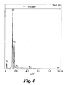
- Figures 4 and 5 are energy dispersive x-ray patterns obtained from each of these two phases of the interfacial layer of the BSAS sample.
- the x-ray spectra show the relative intensities of x-ray emission of various elements when exposed to an electron beam. Intensity, shown on the y-axis, varies with the atomic percentage of a given element.
- the figures reveal that the two phases of the interfacial layer from the BSAS sample have different compositions than the starting BSAS.
- Figure 4 shows the spectrum for the lighter phase 220 of the interfacial layer and shows this phase contained a larger percentage of silicon than the initial BSAS phase pattern shown in Figure 6.
- Figure 5 shows the dispersive x-ray pattern for the darker phase 230 of the interfacial layer and shows the darker phase contained a composition with a very large percentage of aluminum and lower amounts of silicon compared to the initial BSAS phase.
- the substantial change in the silicon to aluminum ratio in both regions of the interfacial layer 210 demonstrates the occurrence of solid state chemical reactions between the BSAS pellet and the silica product of subsurface silicon oxidation.
- interfacial layer contained approximately 35 at% silicon, 0.25 at% aluminum, and 0.06 at% tantalum. This level of tantalum is below the noise level (0.1 at%) of the analysis.
- the thicknesses and compositions of the interfacial layers in the BSAS sample compared to the tantalum aluminate sample indicate that a substantial subsurface chemical reaction occurred between the BSAS pellet and the silica. This reaction did not take place to any appreciable extent in the tantalum aluminate sample demonstrating that the BSAS was less effective at preventing degradation of a silicon bond coat than the tantalum aluminate sample.
Landscapes
- Chemical & Material Sciences (AREA)
- Engineering & Computer Science (AREA)
- Ceramic Engineering (AREA)
- Organic Chemistry (AREA)
- Materials Engineering (AREA)
- Structural Engineering (AREA)
- Metallurgy (AREA)
- Mechanical Engineering (AREA)
- Chemical Kinetics & Catalysis (AREA)
- Inorganic Chemistry (AREA)
- Turbine Rotor Nozzle Sealing (AREA)
- Other Surface Treatments For Metallic Materials (AREA)
- Paints Or Removers (AREA)
Applications Claiming Priority (2)
| Application Number | Priority Date | Filing Date | Title |
|---|---|---|---|
| US678813 | 2003-10-06 | ||
| US10/678,813 US6844075B1 (en) | 2003-10-06 | 2003-10-06 | Environmental barrier coating |
Publications (3)
| Publication Number | Publication Date |
|---|---|
| EP1522535A2 true EP1522535A2 (de) | 2005-04-13 |
| EP1522535A3 EP1522535A3 (de) | 2006-06-07 |
| EP1522535B1 EP1522535B1 (de) | 2008-07-09 |
Family
ID=33565332
Family Applications (1)
| Application Number | Title | Priority Date | Filing Date |
|---|---|---|---|
| EP04256180A Active EP1522535B1 (de) | 2003-10-06 | 2004-10-06 | Wärmedämmschicht |
Country Status (4)
| Country | Link |
|---|---|
| US (1) | US6844075B1 (de) |
| EP (1) | EP1522535B1 (de) |
| JP (1) | JP5265073B2 (de) |
| DE (1) | DE602004014866D1 (de) |
Families Citing this family (30)
| Publication number | Priority date | Publication date | Assignee | Title |
|---|---|---|---|---|
| US7226672B2 (en) * | 2002-08-21 | 2007-06-05 | United Technologies Corporation | Turbine components with thermal barrier coatings |
| US20060246319A1 (en) * | 2005-05-02 | 2006-11-02 | Honeywell International, Inc. | Impact-resistant multilayer coating |
| US7442444B2 (en) | 2005-06-13 | 2008-10-28 | General Electric Company | Bond coat for silicon-containing substrate for EBC and processes for preparing same |
| US7354651B2 (en) | 2005-06-13 | 2008-04-08 | General Electric Company | Bond coat for corrosion resistant EBC for silicon-containing substrate and processes for preparing same |
| US7357994B2 (en) * | 2005-06-14 | 2008-04-15 | General Electric Company | Thermal/environmental barrier coating system for silicon-containing materials |
| EP1984173A2 (de) * | 2006-01-25 | 2008-10-29 | Ceramatec, Inc. | Umgebungs- und wärmesperrbeschichtung für den schutz eines vorbeschichteten substrats |
| US20080026248A1 (en) * | 2006-01-27 | 2008-01-31 | Shekar Balagopal | Environmental and Thermal Barrier Coating to Provide Protection in Various Environments |
| EP1996341B1 (de) * | 2006-02-20 | 2018-09-26 | Kang N. Lee | Artikel mit umgebungsbarriere-beschichtungssystem |
| ES2452519T3 (es) | 2009-05-13 | 2014-04-01 | Sio2 Medical Products, Inc. | Soporte de recipientes |
| US7985188B2 (en) | 2009-05-13 | 2011-07-26 | Cv Holdings Llc | Vessel, coating, inspection and processing apparatus |
| US9458536B2 (en) | 2009-07-02 | 2016-10-04 | Sio2 Medical Products, Inc. | PECVD coating methods for capped syringes, cartridges and other articles |
| US11624115B2 (en) | 2010-05-12 | 2023-04-11 | Sio2 Medical Products, Inc. | Syringe with PECVD lubrication |
| US9878101B2 (en) | 2010-11-12 | 2018-01-30 | Sio2 Medical Products, Inc. | Cyclic olefin polymer vessels and vessel coating methods |
| US9272095B2 (en) | 2011-04-01 | 2016-03-01 | Sio2 Medical Products, Inc. | Vessels, contact surfaces, and coating and inspection apparatus and methods |
| US11116695B2 (en) | 2011-11-11 | 2021-09-14 | Sio2 Medical Products, Inc. | Blood sample collection tube |
| JP6095678B2 (ja) | 2011-11-11 | 2017-03-15 | エスアイオーツー・メディカル・プロダクツ・インコーポレイテッド | 薬剤パッケージ用の不動態化、pH保護又は滑性皮膜、被覆プロセス及び装置 |
| EP2846755A1 (de) | 2012-05-09 | 2015-03-18 | SiO2 Medical Products, Inc. | Saccharidschutzschicht für eine arzneimittelverpackung |
| WO2014071061A1 (en) | 2012-11-01 | 2014-05-08 | Sio2 Medical Products, Inc. | Coating inspection method |
| US9903782B2 (en) | 2012-11-16 | 2018-02-27 | Sio2 Medical Products, Inc. | Method and apparatus for detecting rapid barrier coating integrity characteristics |
| US9764093B2 (en) | 2012-11-30 | 2017-09-19 | Sio2 Medical Products, Inc. | Controlling the uniformity of PECVD deposition |
| BR112015012470B1 (pt) | 2012-11-30 | 2022-08-02 | Sio2 Medical Products, Inc | Método de produção de um tambor médico para um cartucho ou seringa médica |
| WO2014134577A1 (en) | 2013-03-01 | 2014-09-04 | Sio2 Medical Products, Inc. | Plasma or cvd pre-treatment for lubricated pharmaceutical package, coating process and apparatus |
| US9937099B2 (en) | 2013-03-11 | 2018-04-10 | Sio2 Medical Products, Inc. | Trilayer coated pharmaceutical packaging with low oxygen transmission rate |
| CN110074968B (zh) | 2013-03-11 | 2021-12-21 | Sio2医药产品公司 | 涂布包装材料 |
| US20160017490A1 (en) | 2013-03-15 | 2016-01-21 | Sio2 Medical Products, Inc. | Coating method |
| US9068275B2 (en) | 2013-05-08 | 2015-06-30 | General Electric Company | Composite geometrical design for a grain starter in a bridgman investment casting process |
| US9527109B2 (en) | 2013-06-05 | 2016-12-27 | General Electric Company | Coating process and coated article |
| US9938839B2 (en) | 2014-03-14 | 2018-04-10 | General Electric Company | Articles having reduced expansion and hermetic environmental barrier coatings and methods for their manufacture |
| WO2015148471A1 (en) | 2014-03-28 | 2015-10-01 | Sio2 Medical Products, Inc. | Antistatic coatings for plastic vessels |
| US11077233B2 (en) | 2015-08-18 | 2021-08-03 | Sio2 Medical Products, Inc. | Pharmaceutical and other packaging with low oxygen transmission rate |
Citations (5)
| Publication number | Priority date | Publication date | Assignee | Title |
|---|---|---|---|---|
| JPH0834685A (ja) * | 1994-07-26 | 1996-02-06 | Kyocera Corp | 表面被覆窒化珪素質部材 |
| EP0742187A2 (de) * | 1995-05-08 | 1996-11-13 | W. HALDENWANGER TECHNISCHE KERAMIK GMBH & CO. KG | Keramisches Bauteil |
| US5985470A (en) * | 1998-03-16 | 1999-11-16 | General Electric Company | Thermal/environmental barrier coating system for silicon-based materials |
| EP1044947A2 (de) * | 1999-04-15 | 2000-10-18 | United Technologies Corporation | Verfahren zum Aufbringen einer Barriereschicht auf ein siliziumhaltiges Substrat und nach diesem Verfahren hergestellter Gegenstand |
| EP1044943A1 (de) * | 1999-04-15 | 2000-10-18 | United Technologies Corporation | Substrat auf der Basis von Silizium mit einer Umwelt/thermisch Sperrschicht |
Family Cites Families (16)
| Publication number | Priority date | Publication date | Assignee | Title |
|---|---|---|---|---|
| US5391404A (en) | 1993-03-15 | 1995-02-21 | The United States Of America As Represented By The National Aeronautics And Space Administration | Plasma sprayed mullite coatings on silicon-base ceramics |
| US5869146A (en) | 1997-11-12 | 1999-02-09 | United Technologies Corporation | Plasma sprayed mullite coatings on silicon based ceramic materials |
| DE69924065T2 (de) | 1998-04-27 | 2006-04-13 | General Electric Co. | Formkörper mit einem überzug aus modifiziertem mullit und verfahren zu dessen herstellung |
| US6299988B1 (en) | 1998-04-27 | 2001-10-09 | General Electric Company | Ceramic with preferential oxygen reactive layer |
| US6485848B1 (en) | 1998-04-27 | 2002-11-26 | General Electric Company | Coated article and method of making |
| US6129954A (en) | 1998-12-22 | 2000-10-10 | General Electric Company | Method for thermally spraying crack-free mullite coatings on ceramic-based substrates |
| US6296941B1 (en) | 1999-04-15 | 2001-10-02 | General Electric Company | Silicon based substrate with yttrium silicate environmental/thermal barrier layer |
| US6296942B1 (en) | 1999-04-15 | 2001-10-02 | General Electric Company | Silicon based substrate with calcium aluminosilicate environmental/thermal barrier layer |
| US6517960B1 (en) | 1999-04-26 | 2003-02-11 | General Electric Company | Ceramic with zircon coating |
| US6444335B1 (en) | 2000-04-06 | 2002-09-03 | General Electric Company | Thermal/environmental barrier coating for silicon-containing materials |
| US6352790B1 (en) | 2000-06-29 | 2002-03-05 | United Technologies Corporation | Substrate containing silicon and a barrier layer which functions as a protective/thermal barrier coating |
| US6861164B2 (en) | 2001-03-23 | 2005-03-01 | Honeywell International, Inc. | Environmental and thermal barrier coating for ceramic components |
| US6607852B2 (en) | 2001-06-27 | 2003-08-19 | General Electric Company | Environmental/thermal barrier coating system with silica diffusion barrier layer |
| US6617036B2 (en) * | 2001-12-19 | 2003-09-09 | United Technologies Corporation | Barrier layer for silicon containing substrate |
| US6617037B2 (en) | 2001-12-19 | 2003-09-09 | United Technologies Corporation | Silicon based substrate with a CTE compatible layer on the substrate |
| US6589677B1 (en) | 2001-12-19 | 2003-07-08 | United Technologies Corporation | Silicon based substrate with environmental/thermal barrier layer |
-
2003
- 2003-10-06 US US10/678,813 patent/US6844075B1/en not_active Expired - Lifetime
-
2004
- 2004-10-05 JP JP2004292255A patent/JP5265073B2/ja active Active
- 2004-10-06 EP EP04256180A patent/EP1522535B1/de active Active
- 2004-10-06 DE DE602004014866T patent/DE602004014866D1/de active Active
Patent Citations (5)
| Publication number | Priority date | Publication date | Assignee | Title |
|---|---|---|---|---|
| JPH0834685A (ja) * | 1994-07-26 | 1996-02-06 | Kyocera Corp | 表面被覆窒化珪素質部材 |
| EP0742187A2 (de) * | 1995-05-08 | 1996-11-13 | W. HALDENWANGER TECHNISCHE KERAMIK GMBH & CO. KG | Keramisches Bauteil |
| US5985470A (en) * | 1998-03-16 | 1999-11-16 | General Electric Company | Thermal/environmental barrier coating system for silicon-based materials |
| EP1044947A2 (de) * | 1999-04-15 | 2000-10-18 | United Technologies Corporation | Verfahren zum Aufbringen einer Barriereschicht auf ein siliziumhaltiges Substrat und nach diesem Verfahren hergestellter Gegenstand |
| EP1044943A1 (de) * | 1999-04-15 | 2000-10-18 | United Technologies Corporation | Substrat auf der Basis von Silizium mit einer Umwelt/thermisch Sperrschicht |
Non-Patent Citations (1)
| Title |
|---|
| PATENT ABSTRACTS OF JAPAN vol. 1996, no. 06, 28 June 1996 (1996-06-28) & JP 08 034685 A (KYOCERA CORP), 6 February 1996 (1996-02-06) * |
Also Published As
| Publication number | Publication date |
|---|---|
| JP5265073B2 (ja) | 2013-08-14 |
| EP1522535B1 (de) | 2008-07-09 |
| US6844075B1 (en) | 2005-01-18 |
| DE602004014866D1 (de) | 2008-08-21 |
| EP1522535A3 (de) | 2006-06-07 |
| JP2005200764A (ja) | 2005-07-28 |
Similar Documents
| Publication | Publication Date | Title |
|---|---|---|
| EP1522535B1 (de) | Wärmedämmschicht | |
| US20230090598A1 (en) | Article for high temperature service | |
| EP1522534B1 (de) | Aluminatbeschichtung für ein siliziumhaltiges Substrat | |
| US7638178B2 (en) | Protective coating for ceramic components | |
| EP1795515B1 (de) | Sperrschicht für ein Bauteil und zugehöriges Herstellungsverfahren | |
| EP1685083B1 (de) | Oxidationsbarrierebeschichtungen für keramiken auf siliciumbasis | |
| EP2128299B1 (de) | Mehrlagige Wärmedämmschicht | |
| US20060014029A1 (en) | Article including environmental barrier coating system, and method for making | |
| EP1754802B1 (de) | Beschichteter Silikon-enthaltender Werkstoff zum Schützen vor Umweltkorrosion | |
| US7115319B2 (en) | Braze-based protective coating for silicon nitride | |
| JP4113857B2 (ja) | ケイ素基材とボンド層と保護層とを含む物品 | |
| EP1734025B1 (de) | Wärmedämmschichtsystem für siliziumhaltige Werkstoffe | |
| US6582779B2 (en) | Silicon nitride components with protective coating | |
| US20050042461A1 (en) | Diffusion barrier coating for si-based components | |
| US20120223127A1 (en) | Components and methods of forming protective coating systems on components | |
| US20160160374A1 (en) | Methods of forming an article using electrophoretic deposition, and related article |
Legal Events
| Date | Code | Title | Description |
|---|---|---|---|
| PUAI | Public reference made under article 153(3) epc to a published international application that has entered the european phase |
Free format text: ORIGINAL CODE: 0009012 |
|
| AK | Designated contracting states |
Kind code of ref document: A2 Designated state(s): AT BE BG CH CY CZ DE DK EE ES FI FR GB GR HU IE IT LI LU MC NL PL PT RO SE SI SK TR |
|
| AX | Request for extension of the european patent |
Extension state: AL HR LT LV MK |
|
| PUAL | Search report despatched |
Free format text: ORIGINAL CODE: 0009013 |
|
| AK | Designated contracting states |
Kind code of ref document: A3 Designated state(s): AT BE BG CH CY CZ DE DK EE ES FI FR GB GR HU IE IT LI LU MC NL PL PT RO SE SI SK TR |
|
| AX | Request for extension of the european patent |
Extension state: AL HR LT LV MK |
|
| 17P | Request for examination filed |
Effective date: 20061207 |
|
| AKX | Designation fees paid |
Designated state(s): DE FR GB |
|
| 17Q | First examination report despatched |
Effective date: 20070125 |
|
| GRAP | Despatch of communication of intention to grant a patent |
Free format text: ORIGINAL CODE: EPIDOSNIGR1 |
|
| GRAS | Grant fee paid |
Free format text: ORIGINAL CODE: EPIDOSNIGR3 |
|
| GRAA | (expected) grant |
Free format text: ORIGINAL CODE: 0009210 |
|
| AK | Designated contracting states |
Kind code of ref document: B1 Designated state(s): DE FR GB |
|
| REG | Reference to a national code |
Ref country code: GB Ref legal event code: FG4D |
|
| REF | Corresponds to: |
Ref document number: 602004014866 Country of ref document: DE Date of ref document: 20080821 Kind code of ref document: P |
|
| PLBE | No opposition filed within time limit |
Free format text: ORIGINAL CODE: 0009261 |
|
| STAA | Information on the status of an ep patent application or granted ep patent |
Free format text: STATUS: NO OPPOSITION FILED WITHIN TIME LIMIT |
|
| 26N | No opposition filed |
Effective date: 20090414 |
|
| REG | Reference to a national code |
Ref country code: FR Ref legal event code: PLFP Year of fee payment: 12 |
|
| REG | Reference to a national code |
Ref country code: FR Ref legal event code: PLFP Year of fee payment: 13 |
|
| REG | Reference to a national code |
Ref country code: FR Ref legal event code: PLFP Year of fee payment: 14 |
|
| REG | Reference to a national code |
Ref country code: FR Ref legal event code: PLFP Year of fee payment: 15 |
|
| P01 | Opt-out of the competence of the unified patent court (upc) registered |
Effective date: 20230414 |
|
| PGFP | Annual fee paid to national office [announced via postgrant information from national office to epo] |
Ref country code: GB Payment date: 20230920 Year of fee payment: 20 |
|
| PGFP | Annual fee paid to national office [announced via postgrant information from national office to epo] |
Ref country code: FR Payment date: 20230920 Year of fee payment: 20 |
|
| PGFP | Annual fee paid to national office [announced via postgrant information from national office to epo] |
Ref country code: DE Payment date: 20230920 Year of fee payment: 20 |