EP1522464A1 - Protective structure for vehicles - Google Patents
Protective structure for vehicles Download PDFInfo
- Publication number
- EP1522464A1 EP1522464A1 EP04077762A EP04077762A EP1522464A1 EP 1522464 A1 EP1522464 A1 EP 1522464A1 EP 04077762 A EP04077762 A EP 04077762A EP 04077762 A EP04077762 A EP 04077762A EP 1522464 A1 EP1522464 A1 EP 1522464A1
- Authority
- EP
- European Patent Office
- Prior art keywords
- structure according
- crosspiece
- absorption element
- vehicle
- elements
- Prior art date
- Legal status (The legal status is an assumption and is not a legal conclusion. Google has not performed a legal analysis and makes no representation as to the accuracy of the status listed.)
- Granted
Links
- 230000001681 protective effect Effects 0.000 title claims abstract description 17
- 238000010521 absorption reaction Methods 0.000 claims abstract description 30
- 239000004033 plastic Substances 0.000 claims description 11
- 229920003023 plastic Polymers 0.000 claims description 11
- 239000000463 material Substances 0.000 claims description 10
- 230000006835 compression Effects 0.000 claims description 4
- 238000007906 compression Methods 0.000 claims description 4
- 239000004743 Polypropylene Substances 0.000 claims description 2
- 239000004793 Polystyrene Substances 0.000 claims description 2
- 239000004794 expanded polystyrene Substances 0.000 claims description 2
- -1 polypropylene Polymers 0.000 claims description 2
- 229920001155 polypropylene Polymers 0.000 claims description 2
- 229920002223 polystyrene Polymers 0.000 claims description 2
- 229920002635 polyurethane Polymers 0.000 claims description 2
- 239000004814 polyurethane Substances 0.000 claims description 2
- 230000002787 reinforcement Effects 0.000 claims 1
- 230000003014 reinforcing effect Effects 0.000 claims 1
- 239000007769 metal material Substances 0.000 description 3
- 229910000831 Steel Inorganic materials 0.000 description 2
- 239000010959 steel Substances 0.000 description 2
- XAGFODPZIPBFFR-UHFFFAOYSA-N aluminium Chemical compound [Al] XAGFODPZIPBFFR-UHFFFAOYSA-N 0.000 description 1
- 229910052782 aluminium Inorganic materials 0.000 description 1
- 230000005540 biological transmission Effects 0.000 description 1
- 230000000284 resting effect Effects 0.000 description 1
- 238000005728 strengthening Methods 0.000 description 1
Images


Classifications
-
- B—PERFORMING OPERATIONS; TRANSPORTING
- B60—VEHICLES IN GENERAL
- B60R—VEHICLES, VEHICLE FITTINGS, OR VEHICLE PARTS, NOT OTHERWISE PROVIDED FOR
- B60R19/00—Wheel guards; Radiator guards, e.g. grilles; Obstruction removers; Fittings damping bouncing force in collisions
- B60R19/02—Bumpers, i.e. impact receiving or absorbing members for protecting vehicles or fending off blows from other vehicles or objects
- B60R19/24—Arrangements for mounting bumpers on vehicles
- B60R19/26—Arrangements for mounting bumpers on vehicles comprising yieldable mounting means
- B60R19/34—Arrangements for mounting bumpers on vehicles comprising yieldable mounting means destroyed upon impact, e.g. one-shot type
Definitions
- the present invention relates to a protective structure for vehicles suitable for being preferably assembled on the rear side of the vehicle.
- the attention of car manufacturers is currently oriented towards reducing the damage that a vehicle undergoes as a result of collisions at relatively low speeds, typically lower than 15-16 Km/h.
- the protective structure according to the present invention is preferably suitable for impacts having the above characteristics.
- the devices used on vehicles for limiting damage during said collisions on the rear side consist of completely metallic, generally steel, crosspieces, positioned between the vehicle chassis and bumpers; the crosspiece normally rests and is directly fixed to the side-rails, or absorption devices of the metallic type (crash boxes), to which the crosspiece is connected, are fixed to the side-rails.
- absorption elements are also known as “sacrificial elements", which, in the case of collision, absorb most of the impact energy by deforming, and at the same time, preventing the deformation of the vehicle chassis.
- a protective structure for vehicles of the known type typically comprises a pair of impact absorption elements, situated in correspondence with the lateral side-rails of the vehicle chassis, on which a crosspiece is assembled over which a bumper strip is superimposed.
- the crosspiece is normally made of a metallic material, for example aluminum or steel or plastic, whereas the sacrificial elements can be made of a metallic material or plastic material or a complex of elements made of different materials (honeycomb structures).
- the sacrificial elements form the only connection elements between the protective structure of the vehicle with the vehicle chassis itself.
- an impactor will first strike the crosspiece which transfers the load onto the sacrificial elements (in a percentage proportional approximately similar to the impact distance with respect to the two elements).
- the Applicant has considered the problem of increasing the resistance of said protective structure without having to reinforce the crosspiece of the structure and therefore without increasing the weight of the vehicle.
- the Applicant has found that if the supporting points of the protective structure are distributed to a greater extent on the vehicle chassis, and consequently the energy transmission points due to a collision, the structure becomes more efficient and at the same time distributes the absorption energy onto various points of the vehicle.
- the Applicant has produced a protective structure for vehicles in which, in the space present between the sacrificial elements which connect the crosspiece with the side-rails of the chassis, further absorption elements are inserted, which connect the crosspiece itself to the vehicle chassis in the area situated between the two side-rails; in particular, these absorption elements are associated with the substantially vertical outer wall, resting on the housing space of the spare wheel situated on the vehicle chassis, thus forming a closure of the chassis.
- An aspect of the present invention relates to a protective structure for a vehicle, comprising at least one crosspiece externally lined by a bumper strip and fixed to a pair of longitudinal side-rails of the chassis of said vehicle by means of a pair of sacrificial elements, characterized in that it comprises at least one absorption element situated in the space defined by the crosspiece, the sacrificial elements and a bottom wall of the vehicle positioned between the two side-rails.
- the crosspiece 2 is normally made of a metallic or plastic material and is longitudinally shaped as desired according to necessity and space available on the vehicle onto which it is assembled. As far as its transversal section is concerned, this can be "U"-shaped as in the embodiment examples shown in the figures, or of an adequate shape for providing impact resistance (also with a closed section).
- the sacrificial elements 5 and 5' can consist of a single piece, of a plastic or metallic material, or they can consist of more than one element, for example a small base or connection plate 51 with the side-rails 4 which surmounts a sacrificial portion 52.
- Said sacrificial portion consists, for example, of a honeycomb structure made up of a series of elongated elements of a hexagonal transversal section joined together to form a parallelepiped unit.
- the rear part of the vehicle has a shaped bottom portion 7 which is preferably fixed to said side-rails.
- Said shaped bottom portion in association with a bottom wall 8, forms a space 9 for housing the spare wheel.
- Said bottom wall 8 is preferably fixed to the head of the two side-rails 4 and 4'.
- the shaped bottom portion has a pair of slanting surfaces 91 and 91' and a base surface 92 on which the spare wheel of the vehicle rests.
- the protective structure also comprises at least one absorption element situated in the space defined by the crosspiece 2, the sacrificial elements 5 and 5' and the bottom wall 8.
- Said absorption element is preferably fixed to said bottom wall 8 and has such dimensions that its surface is substantially in contact with said crosspiece 2.
- absorption elements 10 and 10' having a substantially parallelepiped shape, situated between said crosspiece 2 and said bottom wall; said elements are situated on the bottom wall in correspondence with the slanting surfaces 91 and 91' of the bottom portion 7, as these slanting surfaces provide a wall strengthening area.
- the absorption elements can be distributed at the same distance from each other in the area defined by the bottom wall, the two side-rails and crosspiece.
- This wall does not have the same resistance as the side-rails (for example 100 KN on the side-rails and 10 ⁇ 15 KN on the bottom wall), upon suitably dimensioning said absorption elements 10, however, the bottom wall also contributes to protecting the overall vehicle chassis.
- absorption elements can be used, which reduce their height by 50% if subjected to a compression of 0.2 to 1.5 N/mm 2 .
- Plastic materials suitable for producing said absorption elements are: expanded polypropylene, expanded polyurethane, expanded polystyrene, polystyrene.
- Figure 3 illustrates an embodiment of the invention in which said absorption elements consist of a combination of two absorption elements situated adjacent to each other, made of different plastic materials, in order to improve the overall characteristics of the absorption element.
- said absorption element 10 or 10' comprises a first substantially parallelepiped portion 101 or 101' and a second substantially parallelepiped portion 102 or 102', superimposed.
Abstract
Description
- The present invention relates to a protective structure for vehicles suitable for being preferably assembled on the rear side of the vehicle.
- The attention of car manufacturers is currently oriented towards reducing the damage that a vehicle undergoes as a result of collisions at relatively low speeds, typically lower than 15-16 Km/h. The protective structure according to the present invention is preferably suitable for impacts having the above characteristics.
- The devices used on vehicles for limiting damage during said collisions on the rear side, consist of completely metallic, generally steel, crosspieces, positioned between the vehicle chassis and bumpers; the crosspiece normally rests and is directly fixed to the side-rails, or absorption devices of the metallic type (crash boxes), to which the crosspiece is connected, are fixed to the side-rails. These absorption elements are also known as "sacrificial elements", which, in the case of collision, absorb most of the impact energy by deforming, and at the same time, preventing the deformation of the vehicle chassis.
- A protective structure for vehicles of the known type, typically comprises a pair of impact absorption elements, situated in correspondence with the lateral side-rails of the vehicle chassis, on which a crosspiece is assembled over which a bumper strip is superimposed.
- The crosspiece is normally made of a metallic material, for example aluminum or steel or plastic, whereas the sacrificial elements can be made of a metallic material or plastic material or a complex of elements made of different materials (honeycomb structures).
- The sacrificial elements form the only connection elements between the protective structure of the vehicle with the vehicle chassis itself.
- During collision, an impactor will first strike the crosspiece which transfers the load onto the sacrificial elements (in a percentage proportional approximately similar to the impact distance with respect to the two elements).
- These structures, for post centered impacts at an equal distance between two sacrificial elements, require extremely rigid crosspieces to be able to transfer the maximum possible force onto the sacrificial elements; this force is defined by the collapse value of the crosspiece. This force, moreover, will then be transferred equally on each side.
- If the crosspiece were extremely rigid (which, by nature, is impossible) it would tend to transfer the force without collapsing and consequently deform the two sacrificial elements thus giving a force to the impactor equal to the sum of the collapse forces of the sacrificial elements.
- If the force transmitted to each crash box or sacrificial element were light, it would be the crosspiece that would be deformed under the impact.
- In order to improve the technical solution, or reduce the intrusion of the obstacle, it is necessary to increase the weight of the crosspiece and consequently of the vehicle.
- The Applicant has considered the problem of increasing the resistance of said protective structure without having to reinforce the crosspiece of the structure and therefore without increasing the weight of the vehicle.
- The Applicant has found that if the supporting points of the protective structure are distributed to a greater extent on the vehicle chassis, and consequently the energy transmission points due to a collision, the structure becomes more efficient and at the same time distributes the absorption energy onto various points of the vehicle.
- For this purpose, the Applicant has produced a protective structure for vehicles in which, in the space present between the sacrificial elements which connect the crosspiece with the side-rails of the chassis, further absorption elements are inserted, which connect the crosspiece itself to the vehicle chassis in the area situated between the two side-rails; in particular, these absorption elements are associated with the substantially vertical outer wall, resting on the housing space of the spare wheel situated on the vehicle chassis, thus forming a closure of the chassis.
- An aspect of the present invention relates to a protective structure for a vehicle, comprising at least one crosspiece externally lined by a bumper strip and fixed to a pair of longitudinal side-rails of the chassis of said vehicle by means of a pair of sacrificial elements, characterized in that it comprises at least one absorption element situated in the space defined by the crosspiece, the sacrificial elements and a bottom wall of the vehicle positioned between the two side-rails.
- The characteristics and advantages of the protective structure according to the present invention will appear more evident from the following illustrative and non-limiting description, referring to the enclosed drawings, wherein:
- figure 1 is an exploded perspective view of the protective structure for vehicles according to the present invention;
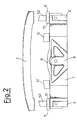
- figure 2 is a partially exploded view from above of the protective structure for vehicles according to the present invention;
- figure 3 is a perspective view of the protective
structure for vehicles according to an alternative
embodiment of the present invention. With reference to
the above figures, the protective structure for a
vehicle according to the present invention comprises at
least one
crosspiece 2, conveniently externally lined by abumper strip 3, fixed to a pair of longitudinal side-rails 4 and 4' of the chassis of a vehicle by means of a pair ofsacrificial elements 5 and 5'. - The
crosspiece 2 is normally made of a metallic or plastic material and is longitudinally shaped as desired according to necessity and space available on the vehicle onto which it is assembled. As far as its transversal section is concerned, this can be "U"-shaped as in the embodiment examples shown in the figures, or of an adequate shape for providing impact resistance (also with a closed section). - The
sacrificial elements 5 and 5' can consist of a single piece, of a plastic or metallic material, or they can consist of more than one element, for example a small base orconnection plate 51 with the side-rails 4 which surmounts asacrificial portion 52. Said sacrificial portion consists, for example, of a honeycomb structure made up of a series of elongated elements of a hexagonal transversal section joined together to form a parallelepiped unit. - Between the two lateral side-rails, the rear part of the vehicle has a
shaped bottom portion 7 which is preferably fixed to said side-rails. Said shaped bottom portion, in association with abottom wall 8, forms aspace 9 for housing the spare wheel. Saidbottom wall 8 is preferably fixed to the head of the two side-rails 4 and 4'. - In order to form said
housing space 9, the shaped bottom portion has a pair ofslanting surfaces 91 and 91' and abase surface 92 on which the spare wheel of the vehicle rests. - According to the present invention, the protective structure also comprises at least one absorption element situated in the space defined by the
crosspiece 2, thesacrificial elements 5 and 5' and thebottom wall 8. - Said absorption element is preferably fixed to said
bottom wall 8 and has such dimensions that its surface is substantially in contact with saidcrosspiece 2. - In the embodiment illustrated in figures 1 and 2, there are two
absorption elements 10 and 10', having a substantially parallelepiped shape, situated between saidcrosspiece 2 and said bottom wall; said elements are situated on the bottom wall in correspondence with theslanting surfaces 91 and 91' of thebottom portion 7, as these slanting surfaces provide a wall strengthening area. - The great majority of vehicles currently have this space for housing the spare wheel and consequently, the bottom wall area with a greater resistance to possible impact and therefore to the compression caused by this, lies in correspondence with said slanting surfaces. If the vehicle has such slanting surfaces, the absorption elements are therefore situated in correspondence with these areas.
- Alternatively, when the bottom portion is flat and does not have this space, the absorption elements can be distributed at the same distance from each other in the area defined by the bottom wall, the two side-rails and crosspiece.
- Any possible impact suffered by the vehicle and consequently a compression strength transmitted by the bumper strip to the crosspiece, is distributed through the
sacrificial elements absorption elements 10 and 10' onto thebottom wall 8. This wall does not have the same resistance as the side-rails (for example 100 KN on the side-rails and 10÷15 KN on the bottom wall), upon suitably dimensioning saidabsorption elements 10, however, the bottom wall also contributes to protecting the overall vehicle chassis. - In particular, absorption elements can be used, which reduce their height by 50% if subjected to a compression of 0.2 to 1.5 N/mm2.
- Plastic materials suitable for producing said absorption elements are: expanded polypropylene, expanded polyurethane, expanded polystyrene, polystyrene.
- Figure 3 illustrates an embodiment of the invention in which said absorption elements consist of a combination of two absorption elements situated adjacent to each other, made of different plastic materials, in order to improve the overall characteristics of the absorption element.
- In particular, said
absorption element 10 or 10' comprises a first substantiallyparallelepiped portion 101 or 101' and a second substantiallyparallelepiped portion 102 or 102', superimposed.
Claims (12)
- A protective structure for a vehicle, comprising at least one crosspiece externally lined by a bumper strip and attached to a pair of longitudinal side-rails of the chassis of said vehicle by means of a pair of sacrificial elements, characterized in that it comprises at least one absorption element situated in the space defined by the crosspiece, the sacrificial elements and a bottom wall of the vehicle positioned between the two side-rails.
- The structure according to claim 1, wherein said at least one absorption element is situated in correspondence with at least one reinforcing area of said bottom wall.
- The structure according to claim 2, comprising two absorption elements each situated close to a side-rail.
- The structure according to claim 3, wherein said absorption element is fixed to said bottom wall and has such dimensions that its surface is substantially in contact with said crosspiece.
- The structure according to claim 1, wherein said absorption element is substantially parallelepiped-shaped.
- The structure according to claim 1, wherein said absorption element is made of a plastic material having the characteristic of reducing its height by 50% when subjected to a compression of 0.2 to 1.5 N/mm2.
- The structure according to claim 6, wherein said absorption element is made of expanded polypropylene or expanded polyurethane or expanded polystyrene or polystyrene.
- The structure according to claim 6, wherein said absorption element comprises a first portion which is substantially parallelepiped and a second portion substantially superimposed and made of a plastic material.
- The structure according to claim 3, wherein said at least one reinforcement area consists of a pair of slanting surfaces forming part of a space for containing the spare wheel.
- The structure according to claim 9, wherein said space is produced in association with a shaped bottom portion of the chassis, defined by said slanting walls and a base, and said bottom wall.
- The structure according to claim 1, wherein the crosspiece is made of a plastic material.
- The structure according to claim 1, wherein the crosspiece is made of a plastic material, the pair of sacrificial elements and the absorption element(s) are made of a plastic material.
Priority Applications (1)
| Application Number | Priority Date | Filing Date | Title |
|---|---|---|---|
| PL04077762T PL1522464T3 (en) | 2003-10-09 | 2004-10-05 | Protective structure for vehicles |
Applications Claiming Priority (2)
| Application Number | Priority Date | Filing Date | Title |
|---|---|---|---|
| IT001944A ITMI20031944A1 (en) | 2003-10-09 | 2003-10-09 | PROTECTION STRUCTURE FOR VEHICLES |
| ITMI20031944 | 2003-10-09 |
Publications (2)
| Publication Number | Publication Date |
|---|---|
| EP1522464A1 true EP1522464A1 (en) | 2005-04-13 |
| EP1522464B1 EP1522464B1 (en) | 2007-02-07 |
Family
ID=34308126
Family Applications (1)
| Application Number | Title | Priority Date | Filing Date |
|---|---|---|---|
| EP04077762A Active EP1522464B1 (en) | 2003-10-09 | 2004-10-05 | Protective structure for vehicles |
Country Status (8)
| Country | Link |
|---|---|
| US (1) | US7494166B2 (en) |
| EP (1) | EP1522464B1 (en) |
| AT (1) | ATE353293T1 (en) |
| BR (1) | BRPI0404358B1 (en) |
| DE (1) | DE602004004613T2 (en) |
| ES (1) | ES2281750T3 (en) |
| IT (1) | ITMI20031944A1 (en) |
| PL (1) | PL1522464T3 (en) |
Cited By (3)
| Publication number | Priority date | Publication date | Assignee | Title |
|---|---|---|---|---|
| EP1775172A3 (en) * | 2005-10-14 | 2008-03-05 | GM Global Technology Operations, Inc. | Device for absorbing shocks |
| FR2977222A3 (en) * | 2011-07-01 | 2013-01-04 | Renault Sa | Chassis for car, has reinforcement defining spacer and fixed at shock absorber that is placed in vicinity of crosspiece and rear skirt, where reinforcement extending in hollow body is defined in rear skirt unit |
| EP2666675A1 (en) * | 2012-05-22 | 2013-11-27 | Honda Motor Co., Ltd. | Vehicle body rear structure |
Families Citing this family (5)
| Publication number | Priority date | Publication date | Assignee | Title |
|---|---|---|---|---|
| US8042852B2 (en) * | 2007-12-21 | 2011-10-25 | Honda Motor Co., Ltd. | Method for mounting flanged plastic garnish with support post, for painting on-line |
| US7866716B2 (en) | 2008-04-08 | 2011-01-11 | Flex-N-Gate Corporation | Energy absorber for vehicle |
| DE102014101614B4 (en) * | 2013-11-19 | 2021-09-23 | Dr. Ing. H.C. F. Porsche Aktiengesellschaft | Method of assembling a device for transmitting an impact pulse |
| US10065587B2 (en) | 2015-11-23 | 2018-09-04 | Flex|N|Gate Corporation | Multi-layer energy absorber |
| US10494034B2 (en) | 2017-09-25 | 2019-12-03 | Ford Global Technologies, Llc | Vehicle frame assembly |
Citations (3)
| Publication number | Priority date | Publication date | Assignee | Title |
|---|---|---|---|---|
| US3694019A (en) * | 1970-11-23 | 1972-09-26 | Allied Chem | Single use inertia absorbing device |
| DE19604215A1 (en) * | 1995-02-16 | 1996-08-22 | Volkswagen Ag | Vehicle using spare wheel as element of impact absorbing equipment |
| US20030085591A1 (en) * | 2001-10-16 | 2003-05-08 | Seksaria Dinesh C | Modular front end for a motor vehicle |
Family Cites Families (2)
| Publication number | Priority date | Publication date | Assignee | Title |
|---|---|---|---|---|
| JPS62128852A (en) * | 1985-11-29 | 1987-06-11 | Honda Motor Co Ltd | Bumper made of synthetic resin for automobile |
| ATE240858T1 (en) * | 2000-08-10 | 2003-06-15 | Benteler Werke Ag | TWO-SHELF SUPPORT WITH OPEN PROFILE FOR A BUMPER |
-
2003
- 2003-10-09 IT IT001944A patent/ITMI20031944A1/en unknown
-
2004
- 2004-10-05 DE DE602004004613T patent/DE602004004613T2/en active Active
- 2004-10-05 US US10/958,718 patent/US7494166B2/en active Active
- 2004-10-05 EP EP04077762A patent/EP1522464B1/en active Active
- 2004-10-05 AT AT04077762T patent/ATE353293T1/en not_active IP Right Cessation
- 2004-10-05 ES ES04077762T patent/ES2281750T3/en active Active
- 2004-10-05 PL PL04077762T patent/PL1522464T3/en unknown
- 2004-10-07 BR BRPI0404358-8A patent/BRPI0404358B1/en active IP Right Grant
Patent Citations (3)
| Publication number | Priority date | Publication date | Assignee | Title |
|---|---|---|---|---|
| US3694019A (en) * | 1970-11-23 | 1972-09-26 | Allied Chem | Single use inertia absorbing device |
| DE19604215A1 (en) * | 1995-02-16 | 1996-08-22 | Volkswagen Ag | Vehicle using spare wheel as element of impact absorbing equipment |
| US20030085591A1 (en) * | 2001-10-16 | 2003-05-08 | Seksaria Dinesh C | Modular front end for a motor vehicle |
Cited By (4)
| Publication number | Priority date | Publication date | Assignee | Title |
|---|---|---|---|---|
| EP1775172A3 (en) * | 2005-10-14 | 2008-03-05 | GM Global Technology Operations, Inc. | Device for absorbing shocks |
| FR2977222A3 (en) * | 2011-07-01 | 2013-01-04 | Renault Sa | Chassis for car, has reinforcement defining spacer and fixed at shock absorber that is placed in vicinity of crosspiece and rear skirt, where reinforcement extending in hollow body is defined in rear skirt unit |
| EP2666675A1 (en) * | 2012-05-22 | 2013-11-27 | Honda Motor Co., Ltd. | Vehicle body rear structure |
| US8888151B2 (en) | 2012-05-22 | 2014-11-18 | Honda Motor Co., Ltd. | Vehicle body rear structure |
Also Published As
| Publication number | Publication date |
|---|---|
| PL1522464T3 (en) | 2007-08-31 |
| US7494166B2 (en) | 2009-02-24 |
| DE602004004613T2 (en) | 2007-10-31 |
| DE602004004613D1 (en) | 2007-03-22 |
| BRPI0404358B1 (en) | 2021-01-05 |
| US20050077739A1 (en) | 2005-04-14 |
| ITMI20031944A1 (en) | 2005-04-10 |
| EP1522464B1 (en) | 2007-02-07 |
| ATE353293T1 (en) | 2007-02-15 |
| BRPI0404358A (en) | 2005-06-14 |
| ES2281750T3 (en) | 2007-10-01 |
Similar Documents
| Publication | Publication Date | Title |
|---|---|---|
| JP4004924B2 (en) | Bumper device for vehicle | |
| JP4048080B2 (en) | Bumper device for vehicle and bumper stay | |
| US4272114A (en) | Impact absorbing device | |
| EP0434240B1 (en) | Vehicle bumper system | |
| JP4872541B2 (en) | Automotive bumper structure | |
| CA1240345A (en) | Impact attenuating body | |
| US4190276A (en) | Deformable impact absorbing device for vehicles | |
| US6485072B1 (en) | Bumper system for motor vehicles | |
| JP2745387B2 (en) | Passenger cars with rigid floor structures | |
| US5385375A (en) | Reinforced impact beam for a bumper assembly and method of manufacture | |
| EP2116445B1 (en) | Rear structure of vehicle body | |
| US20010013706A1 (en) | Device for the absorption of impact energy in motor vehicles and method of making same | |
| EP2113425A1 (en) | Side impact guard device for industrial vechicles, particularly trailers or semi-trailers | |
| EP1726490B1 (en) | Vehicle body front part structure of automobile | |
| KR19980044132A (en) | Bumper Mounting Structure | |
| EP1522464B1 (en) | Protective structure for vehicles | |
| JP2012517373A (en) | Vehicle body, especially land vehicle body | |
| US20040135384A1 (en) | Bumper assembly | |
| JP2000318552A (en) | Bumper | |
| EP1264739B1 (en) | Protective structure for vehicles | |
| JP3870677B2 (en) | Shock absorber for moving body | |
| US7503602B1 (en) | Energy absorbing bumper | |
| JP3562919B2 (en) | Shock absorbing bumper | |
| US3752523A (en) | Impact absorbing vehicle bumper | |
| JPH03227750A (en) | Car bumper |
Legal Events
| Date | Code | Title | Description |
|---|---|---|---|
| PUAI | Public reference made under article 153(3) epc to a published international application that has entered the european phase |
Free format text: ORIGINAL CODE: 0009012 |
|
| AK | Designated contracting states |
Kind code of ref document: A1 Designated state(s): AT BE BG CH CY CZ DE DK EE ES FI FR GB GR HU IE IT LI LU MC NL PL PT RO SE SI SK TR |
|
| AX | Request for extension of the european patent |
Extension state: AL HR LT LV MK |
|
| 17P | Request for examination filed |
Effective date: 20050913 |
|
| AKX | Designation fees paid |
Designated state(s): AT BE BG CH CY CZ DE DK EE ES FI FR GB GR HU IE IT LI LU MC NL PL PT RO SE SI SK TR |
|
| GRAP | Despatch of communication of intention to grant a patent |
Free format text: ORIGINAL CODE: EPIDOSNIGR1 |
|
| GRAS | Grant fee paid |
Free format text: ORIGINAL CODE: EPIDOSNIGR3 |
|
| GRAA | (expected) grant |
Free format text: ORIGINAL CODE: 0009210 |
|
| AK | Designated contracting states |
Kind code of ref document: B1 Designated state(s): AT BE BG CH CY CZ DE DK EE ES FI FR GB GR HU IE IT LI LU MC NL PL PT RO SE SI SK TR |
|
| PG25 | Lapsed in a contracting state [announced via postgrant information from national office to epo] |
Ref country code: NL Free format text: LAPSE BECAUSE OF FAILURE TO SUBMIT A TRANSLATION OF THE DESCRIPTION OR TO PAY THE FEE WITHIN THE PRESCRIBED TIME-LIMIT Effective date: 20070207 Ref country code: LI Free format text: LAPSE BECAUSE OF FAILURE TO SUBMIT A TRANSLATION OF THE DESCRIPTION OR TO PAY THE FEE WITHIN THE PRESCRIBED TIME-LIMIT Effective date: 20070207 Ref country code: SI Free format text: LAPSE BECAUSE OF FAILURE TO SUBMIT A TRANSLATION OF THE DESCRIPTION OR TO PAY THE FEE WITHIN THE PRESCRIBED TIME-LIMIT Effective date: 20070207 Ref country code: DK Free format text: LAPSE BECAUSE OF FAILURE TO SUBMIT A TRANSLATION OF THE DESCRIPTION OR TO PAY THE FEE WITHIN THE PRESCRIBED TIME-LIMIT Effective date: 20070207 Ref country code: FI Free format text: LAPSE BECAUSE OF FAILURE TO SUBMIT A TRANSLATION OF THE DESCRIPTION OR TO PAY THE FEE WITHIN THE PRESCRIBED TIME-LIMIT Effective date: 20070207 Ref country code: AT Free format text: LAPSE BECAUSE OF FAILURE TO SUBMIT A TRANSLATION OF THE DESCRIPTION OR TO PAY THE FEE WITHIN THE PRESCRIBED TIME-LIMIT Effective date: 20070207 Ref country code: CH Free format text: LAPSE BECAUSE OF FAILURE TO SUBMIT A TRANSLATION OF THE DESCRIPTION OR TO PAY THE FEE WITHIN THE PRESCRIBED TIME-LIMIT Effective date: 20070207 Ref country code: BE Free format text: LAPSE BECAUSE OF FAILURE TO SUBMIT A TRANSLATION OF THE DESCRIPTION OR TO PAY THE FEE WITHIN THE PRESCRIBED TIME-LIMIT Effective date: 20070207 |
|
| REG | Reference to a national code |
Ref country code: GB Ref legal event code: FG4D |
|
| REG | Reference to a national code |
Ref country code: CH Ref legal event code: EP |
|
| REG | Reference to a national code |
Ref country code: IE Ref legal event code: FG4D |
|
| REF | Corresponds to: |
Ref document number: 602004004613 Country of ref document: DE Date of ref document: 20070322 Kind code of ref document: P |
|
| PG25 | Lapsed in a contracting state [announced via postgrant information from national office to epo] |
Ref country code: SE Free format text: LAPSE BECAUSE OF FAILURE TO SUBMIT A TRANSLATION OF THE DESCRIPTION OR TO PAY THE FEE WITHIN THE PRESCRIBED TIME-LIMIT Effective date: 20070507 |
|
| PG25 | Lapsed in a contracting state [announced via postgrant information from national office to epo] |
Ref country code: BG Free format text: LAPSE BECAUSE OF FAILURE TO SUBMIT A TRANSLATION OF THE DESCRIPTION OR TO PAY THE FEE WITHIN THE PRESCRIBED TIME-LIMIT Effective date: 20070508 |
|
| RAP2 | Party data changed (patent owner data changed or rights of a patent transferred) |
Owner name: AVELDA S.R.L |
|
| PG25 | Lapsed in a contracting state [announced via postgrant information from national office to epo] |
Ref country code: PT Free format text: LAPSE BECAUSE OF FAILURE TO SUBMIT A TRANSLATION OF THE DESCRIPTION OR TO PAY THE FEE WITHIN THE PRESCRIBED TIME-LIMIT Effective date: 20070709 |
|
| NLT2 | Nl: modifications (of names), taken from the european patent patent bulletin |
Owner name: AVELDA S.R.L Effective date: 20070530 |
|
| NLV1 | Nl: lapsed or annulled due to failure to fulfill the requirements of art. 29p and 29m of the patents act | ||
| REG | Reference to a national code |
Ref country code: CH Ref legal event code: PL |
|
| ET | Fr: translation filed | ||
| REG | Reference to a national code |
Ref country code: PL Ref legal event code: T3 |
|
| REG | Reference to a national code |
Ref country code: ES Ref legal event code: FG2A Ref document number: 2281750 Country of ref document: ES Kind code of ref document: T3 |
|
| PG25 | Lapsed in a contracting state [announced via postgrant information from national office to epo] |
Ref country code: SK Free format text: LAPSE BECAUSE OF FAILURE TO SUBMIT A TRANSLATION OF THE DESCRIPTION OR TO PAY THE FEE WITHIN THE PRESCRIBED TIME-LIMIT Effective date: 20070207 |
|
| PLBE | No opposition filed within time limit |
Free format text: ORIGINAL CODE: 0009261 |
|
| STAA | Information on the status of an ep patent application or granted ep patent |
Free format text: STATUS: NO OPPOSITION FILED WITHIN TIME LIMIT |
|
| PG25 | Lapsed in a contracting state [announced via postgrant information from national office to epo] |
Ref country code: CZ Free format text: LAPSE BECAUSE OF FAILURE TO SUBMIT A TRANSLATION OF THE DESCRIPTION OR TO PAY THE FEE WITHIN THE PRESCRIBED TIME-LIMIT Effective date: 20070207 Ref country code: RO Free format text: LAPSE BECAUSE OF FAILURE TO SUBMIT A TRANSLATION OF THE DESCRIPTION OR TO PAY THE FEE WITHIN THE PRESCRIBED TIME-LIMIT Effective date: 20070207 |
|
| 26N | No opposition filed |
Effective date: 20071108 |
|
| PG25 | Lapsed in a contracting state [announced via postgrant information from national office to epo] |
Ref country code: GR Free format text: LAPSE BECAUSE OF FAILURE TO SUBMIT A TRANSLATION OF THE DESCRIPTION OR TO PAY THE FEE WITHIN THE PRESCRIBED TIME-LIMIT Effective date: 20070508 |
|
| PG25 | Lapsed in a contracting state [announced via postgrant information from national office to epo] |
Ref country code: MC Free format text: LAPSE BECAUSE OF NON-PAYMENT OF DUE FEES Effective date: 20071031 |
|
| PG25 | Lapsed in a contracting state [announced via postgrant information from national office to epo] |
Ref country code: IE Free format text: LAPSE BECAUSE OF NON-PAYMENT OF DUE FEES Effective date: 20071005 |
|
| PG25 | Lapsed in a contracting state [announced via postgrant information from national office to epo] |
Ref country code: EE Free format text: LAPSE BECAUSE OF FAILURE TO SUBMIT A TRANSLATION OF THE DESCRIPTION OR TO PAY THE FEE WITHIN THE PRESCRIBED TIME-LIMIT Effective date: 20070207 |
|
| GBPC | Gb: european patent ceased through non-payment of renewal fee |
Effective date: 20081005 |
|
| PG25 | Lapsed in a contracting state [announced via postgrant information from national office to epo] |
Ref country code: CY Free format text: LAPSE BECAUSE OF FAILURE TO SUBMIT A TRANSLATION OF THE DESCRIPTION OR TO PAY THE FEE WITHIN THE PRESCRIBED TIME-LIMIT Effective date: 20070207 |
|
| PG25 | Lapsed in a contracting state [announced via postgrant information from national office to epo] |
Ref country code: LU Free format text: LAPSE BECAUSE OF NON-PAYMENT OF DUE FEES Effective date: 20071005 |
|
| PG25 | Lapsed in a contracting state [announced via postgrant information from national office to epo] |
Ref country code: HU Free format text: LAPSE BECAUSE OF FAILURE TO SUBMIT A TRANSLATION OF THE DESCRIPTION OR TO PAY THE FEE WITHIN THE PRESCRIBED TIME-LIMIT Effective date: 20070808 |
|
| PG25 | Lapsed in a contracting state [announced via postgrant information from national office to epo] |
Ref country code: GB Free format text: LAPSE BECAUSE OF NON-PAYMENT OF DUE FEES Effective date: 20081005 |
|
| REG | Reference to a national code |
Ref country code: DE Ref legal event code: R082 Ref document number: 602004004613 Country of ref document: DE Representative=s name: WEBER & HEIM PATENTANWAELTE, DE |
|
| REG | Reference to a national code |
Ref country code: ES Ref legal event code: PC2A Owner name: VM PLASTICS S.R.L. Effective date: 20120229 |
|
| REG | Reference to a national code |
Ref country code: DE Ref legal event code: R081 Ref document number: 602004004613 Country of ref document: DE Owner name: VM PLASTICS S.R.L., IT Free format text: FORMER OWNER: AVELDA S.R.L., MILAN, IT Effective date: 20120215 Ref country code: DE Ref legal event code: R082 Ref document number: 602004004613 Country of ref document: DE Representative=s name: WEBER & HEIM PATENTANWAELTE, DE Effective date: 20120215 Ref country code: DE Ref legal event code: R082 Ref document number: 602004004613 Country of ref document: DE Representative=s name: WEBER & HEIM PATENTANWAELTE PARTNERSCHAFTSGESE, DE Effective date: 20120215 Ref country code: DE Ref legal event code: R082 Ref document number: 602004004613 Country of ref document: DE Representative=s name: WUNDERLICH & HEIM PATENTANWAELTE PARTNERSCHAFT, DE Effective date: 20120215 |
|
| REG | Reference to a national code |
Ref country code: FR Ref legal event code: TP Owner name: VM PLASTICS S.R.L., IT Effective date: 20120326 |
|
| REG | Reference to a national code |
Ref country code: FR Ref legal event code: PLFP Year of fee payment: 12 |
|
| REG | Reference to a national code |
Ref country code: FR Ref legal event code: PLFP Year of fee payment: 13 |
|
| REG | Reference to a national code |
Ref country code: FR Ref legal event code: PLFP Year of fee payment: 14 |
|
| REG | Reference to a national code |
Ref country code: DE Ref legal event code: R082 Ref document number: 602004004613 Country of ref document: DE Representative=s name: WUNDERLICH & HEIM PATENTANWAELTE PARTNERSCHAFT, DE |
|
| REG | Reference to a national code |
Ref country code: FR Ref legal event code: PLFP Year of fee payment: 15 |
|
| PGFP | Annual fee paid to national office [announced via postgrant information from national office to epo] |
Ref country code: PL Payment date: 20230922 Year of fee payment: 20 |
|
| PGFP | Annual fee paid to national office [announced via postgrant information from national office to epo] |
Ref country code: ES Payment date: 20231222 Year of fee payment: 20 |
|
| PGFP | Annual fee paid to national office [announced via postgrant information from national office to epo] |
Ref country code: TR Payment date: 20231002 Year of fee payment: 20 Ref country code: IT Payment date: 20231017 Year of fee payment: 20 Ref country code: FR Payment date: 20231023 Year of fee payment: 20 Ref country code: DE Payment date: 20231020 Year of fee payment: 20 |