EP1522397B1 - Apparatus for shaping heated thermoplastic plates or sheets - Google Patents
Apparatus for shaping heated thermoplastic plates or sheets Download PDFInfo
- Publication number
- EP1522397B1 EP1522397B1 EP04023859A EP04023859A EP1522397B1 EP 1522397 B1 EP1522397 B1 EP 1522397B1 EP 04023859 A EP04023859 A EP 04023859A EP 04023859 A EP04023859 A EP 04023859A EP 1522397 B1 EP1522397 B1 EP 1522397B1
- Authority
- EP
- European Patent Office
- Prior art keywords
- heater
- pneumatic cylinder
- cylinder
- heating apparatus
- heating
- Prior art date
- Legal status (The legal status is an assumption and is not a legal conclusion. Google has not performed a legal analysis and makes no representation as to the accuracy of the status listed.)
- Expired - Lifetime
Links
- 238000007493 shaping process Methods 0.000 title claims 2
- 229920001169 thermoplastic Polymers 0.000 title claims 2
- 239000004416 thermosoftening plastic Substances 0.000 title 1
- 238000010438 heat treatment Methods 0.000 claims abstract description 30
- 238000013016 damping Methods 0.000 claims description 4
- 238000006073 displacement reaction Methods 0.000 claims description 4
- 238000000465 moulding Methods 0.000 claims 2
- 239000004033 plastic Substances 0.000 abstract description 5
- 238000010792 warming Methods 0.000 abstract description 3
- 230000000284 resting effect Effects 0.000 abstract 1
- 239000012530 fluid Substances 0.000 description 3
- 230000008878 coupling Effects 0.000 description 2
- 238000010168 coupling process Methods 0.000 description 2
- 238000005859 coupling reaction Methods 0.000 description 2
- 238000011161 development Methods 0.000 description 2
- 239000012815 thermoplastic material Substances 0.000 description 2
- 238000013459 approach Methods 0.000 description 1
- 239000000919 ceramic Substances 0.000 description 1
- 238000001816 cooling Methods 0.000 description 1
- 230000000694 effects Effects 0.000 description 1
- 238000004146 energy storage Methods 0.000 description 1
- 238000002474 experimental method Methods 0.000 description 1
- 239000011888 foil Substances 0.000 description 1
- 229910052736 halogen Inorganic materials 0.000 description 1
- 150000002367 halogens Chemical class 0.000 description 1
- 238000000034 method Methods 0.000 description 1
- 239000010453 quartz Substances 0.000 description 1
- 230000035945 sensitivity Effects 0.000 description 1
- VYPSYNLAJGMNEJ-UHFFFAOYSA-N silicon dioxide Inorganic materials O=[Si]=O VYPSYNLAJGMNEJ-UHFFFAOYSA-N 0.000 description 1
- 238000012360 testing method Methods 0.000 description 1
- 238000011144 upstream manufacturing Methods 0.000 description 1
Images

Classifications
-
- B—PERFORMING OPERATIONS; TRANSPORTING
- B29—WORKING OF PLASTICS; WORKING OF SUBSTANCES IN A PLASTIC STATE IN GENERAL
- B29C—SHAPING OR JOINING OF PLASTICS; SHAPING OF MATERIAL IN A PLASTIC STATE, NOT OTHERWISE PROVIDED FOR; AFTER-TREATMENT OF THE SHAPED PRODUCTS, e.g. REPAIRING
- B29C51/00—Shaping by thermoforming, i.e. shaping sheets or sheet like preforms after heating, e.g. shaping sheets in matched moulds or by deep-drawing; Apparatus therefor
- B29C51/26—Component parts, details or accessories; Auxiliary operations
- B29C51/42—Heating or cooling
- B29C51/421—Heating or cooling of preforms, specially adapted for thermoforming
- B29C51/425—Heating or cooling of preforms, specially adapted for thermoforming using movable heating devices
-
- B—PERFORMING OPERATIONS; TRANSPORTING
- B29—WORKING OF PLASTICS; WORKING OF SUBSTANCES IN A PLASTIC STATE IN GENERAL
- B29C—SHAPING OR JOINING OF PLASTICS; SHAPING OF MATERIAL IN A PLASTIC STATE, NOT OTHERWISE PROVIDED FOR; AFTER-TREATMENT OF THE SHAPED PRODUCTS, e.g. REPAIRING
- B29C51/00—Shaping by thermoforming, i.e. shaping sheets or sheet like preforms after heating, e.g. shaping sheets in matched moulds or by deep-drawing; Apparatus therefor
- B29C51/26—Component parts, details or accessories; Auxiliary operations
- B29C51/46—Measuring, controlling or regulating
-
- B—PERFORMING OPERATIONS; TRANSPORTING
- B29—WORKING OF PLASTICS; WORKING OF SUBSTANCES IN A PLASTIC STATE IN GENERAL
- B29C—SHAPING OR JOINING OF PLASTICS; SHAPING OF MATERIAL IN A PLASTIC STATE, NOT OTHERWISE PROVIDED FOR; AFTER-TREATMENT OF THE SHAPED PRODUCTS, e.g. REPAIRING
- B29C35/00—Heating, cooling or curing, e.g. crosslinking or vulcanising; Apparatus therefor
- B29C35/02—Heating or curing, e.g. crosslinking or vulcanizing during moulding, e.g. in a mould
- B29C35/08—Heating or curing, e.g. crosslinking or vulcanizing during moulding, e.g. in a mould by wave energy or particle radiation
- B29C35/0805—Heating or curing, e.g. crosslinking or vulcanizing during moulding, e.g. in a mould by wave energy or particle radiation using electromagnetic radiation
- B29C2035/0822—Heating or curing, e.g. crosslinking or vulcanizing during moulding, e.g. in a mould by wave energy or particle radiation using electromagnetic radiation using IR radiation
-
- B—PERFORMING OPERATIONS; TRANSPORTING
- B29—WORKING OF PLASTICS; WORKING OF SUBSTANCES IN A PLASTIC STATE IN GENERAL
- B29C—SHAPING OR JOINING OF PLASTICS; SHAPING OF MATERIAL IN A PLASTIC STATE, NOT OTHERWISE PROVIDED FOR; AFTER-TREATMENT OF THE SHAPED PRODUCTS, e.g. REPAIRING
- B29C2793/00—Shaping techniques involving a cutting or machining operation
- B29C2793/0081—Shaping techniques involving a cutting or machining operation before shaping
-
- B—PERFORMING OPERATIONS; TRANSPORTING
- B29—WORKING OF PLASTICS; WORKING OF SUBSTANCES IN A PLASTIC STATE IN GENERAL
- B29C—SHAPING OR JOINING OF PLASTICS; SHAPING OF MATERIAL IN A PLASTIC STATE, NOT OTHERWISE PROVIDED FOR; AFTER-TREATMENT OF THE SHAPED PRODUCTS, e.g. REPAIRING
- B29C51/00—Shaping by thermoforming, i.e. shaping sheets or sheet like preforms after heating, e.g. shaping sheets in matched moulds or by deep-drawing; Apparatus therefor
- B29C51/04—Combined thermoforming and prestretching, e.g. biaxial stretching
Definitions
- the invention relates to a device for deforming heated plates or film web sections made of thermoplastic material according to the preamble of the main claim.
- the heater is moved horizontally between a heating position above the plate or above the film web portion and a rest position.
- the heating position is either in the forming station, then the heater is moved in this per cycle between rest position and forming station and / or a heating station is the Formstation vorun, and a transport device is used to transport the plate or the film web section between the heating station and forming station.
- the movement of the heater should be done as quickly as possible, because the travel time for certain machine versions directly affects the cycle time.
- the so-called Kochfahr so ie the heater moves from the rest position first on the plate and after heating back. This means that one side of the plate, which passes over the heater first, is heated longer than the side over which the heater arrives at the end of the movement. On the return trip, it is the other way around, ie the longer heated side of the ancestor is now heated again longer, because the heater leaves this page last. This could only be countered by two rest positions - opposite - which is not possible for a variety of reasons.
- the publication GB-A-1 483 454 describes a device for producing cup-shaped recessed plastic plates, which may also be designed as a double machine, wherein two devices are arranged next to each other. While in one machine the plastic plate is heated to deform, the plastic plate of the other machine is in the cooling phase after the deformation has taken place. If the respective heating phase is completed, a heating device which is formed only once, moved from one to the other device.
- the drive of the slidable heater is designed as a fluid system having throttles that are manually infinitely adjustable to adjust the speed of the displacement of the heater. The heater is moved at a constant speed between the two deformation devices. A possibility for influencing the speed during the shift is not provided.
- the font US-A-3787159 shows a twinsheet thermoformer with fixed heater and slidable plate conveyor.
- the drive of the plate transport device is designed as a fluid drive.
- stationary limit switches which are arranged on the displacement distance of the plate transport device, the fluid is alternatively passed through two different paths, which have different displacement speeds result.
- the shift begins with a higher speed, which is switched to a lower speed by means of the limit switch. A possibility for influencing the low speed during the shift is not provided.
- the device moves at constant speed to the end position.
- the invention has for its object to make the device so that the movement of the heater takes place quickly and still with a soft start of the end positions and in case of power failure driving in rest position to avoid a fire hazard can be made without consuming expensive measures.
- the device consists of a forming station 1 with two clamping frames 2, 3, of which the upper clamping frame 2 is vertically displaceable and both of which cooperate in clamping a plate 4 or a foil web section of thermoplastic material.
- a heating device 5 arranged in the forming station 1 and / or in the charging station 6, the heating of the plate 4 or the film web section takes place on deformation temperature.
- the plate 4 or the film web section is deep-drawn into a molded part 9. If necessary, deep-drawing is assisted by a pre-stretching device 10, which is connected to a drive device 11 via a coupling 12.
- the side of the forming station 1 is optionally a loading station 6 is arranged, in which the plates 4 are inserted as a stack 13.
- the uppermost plate 4 of the stack 13 is lifted off in each case via a suction plate 14 with suction devices 15 which can be connected to a vacuum and transferred to the transport device 19 which connects the two stations 6, 1.
- Drive means 16 and suction plate 14 are connected via the coupling 17.
- a film web 18 is withdrawn from a roll 21 by means of a transport device 19, a cross cutter 20 separates these film web sections and the transport device 19 brings them into the individual stations 6.1.
- a heating device 5 is arranged, which consists of an upper heating and possibly a sub-heater and is generally referred to as a heating device 5.
- a continuously variable in cross-section throttle 26 is installed, which is designed so that its cross section can be changed by a controller 27 via a control line 28.
- the throttle 26 may be a proportional valve whose cross-section is proportional to the applied voltage.
- Each heater 5 is provided with any commercially available position measuring system 30, with which the position of the heater 5 is detected and reported via a control line 28 of the controller 27.
- this measuring system 30 is a single - preferably adjustable - switches that report a particular reached position of the heater to the controller 27.
- the throttle 26 for supplying the compressed air for generating the movement is now fully opened, the exhaust-side throttle 26 also initially.
- the heater 5 moves very quickly.
- a reduction of the cross-section is preferably the corresponding exhaust-side throttle 26 and thus throttling the driving speed in such a way that the movement comes to a stop in the final position, without a jerky deceleration occurs.
- An additional change in the cross section of the supply-side throttle 26 is possible.
- FIG. 1 Another possibility of throttling the travel movement of the heating device 5 as a function of its position is shown in FIG.
- a damping cylinder 34 is arranged with piston 38.
- the piston rod 36 of the pneumatic cylinder 23 is connected to the piston rod 35 of the damping cylinder 34 - or optionally also directly to the heater 5 - connected.
- the damping cylinder 34 is filled with oil and the oil passes over the connecting line 37 between the two sides of the cylinder.
- a throttle 26 is installed, which can be changed in cross-section by appropriate control via the controller 27.
- the time of the beginning of the throttling and the speed of the throttling can be determined once by tests and stored in the controller 27. It has in this way an optimally fast movement of the heater 5 without risk of damaging their heating elements.
- This pressure accumulator 32 is fed via the compressed air source 29 and a check valve 33.
- the through valve 31 is closed, it opens in case of power failure and thus connects one side of the pneumatic cylinder 23 with the compressed air reservoir 32, whereby the movement of the heater 5 is in the rest position 22.
Landscapes
- Engineering & Computer Science (AREA)
- Mechanical Engineering (AREA)
- Blow-Moulding Or Thermoforming Of Plastics Or The Like (AREA)
- Shaping Of Tube Ends By Bending Or Straightening (AREA)
- Processing And Handling Of Plastics And Other Materials For Molding In General (AREA)
Abstract
Description
Die Erfindung betrifft eine Vorrichtung zum Verformen von erwärmten Platten oder Folienbahnabschnitten aus thermoplastischem Kunststoff nach der Gattung des Hauptanspruches.The invention relates to a device for deforming heated plates or film web sections made of thermoplastic material according to the preamble of the main claim.
Bei einer solchen Vorrichtung wird die Heizeinrichtung horizontal verschoben zwischen einer Heizstellung über der Platte oder über dem Folienbahnabschnitt und einer Ruheposition. Die Heizstellung ist dabei entweder in der Formstation, dann wird die Heizeinrichtung in dieser pro Takt zwischen Ruheposition und Formstation verfahren und/oder eine Heizstation ist der Formstation vorangesetzt, und eine Transporteinrichtung dient dem Transport der Platte oder des Folienbahnabschnittes zwischen Heizstation und Formstation.In such a device, the heater is moved horizontally between a heating position above the plate or above the film web portion and a rest position. The heating position is either in the forming station, then the heater is moved in this per cycle between rest position and forming station and / or a heating station is the Formstation vorgesetzt, and a transport device is used to transport the plate or the film web section between the heating station and forming station.
Bezüglich der Heizungsbewegung gibt es verschiedene Anforderungen. So soll die Bewegung der Heizeinrichtung möglichst rasch erfolgen, weil die Fahrzeit bei bestimmten Maschinenausführungen direkt die Taktzeit beeinflusst. Hinzu kommt der sogenannte Überfahreffekt, d.h. die Heizeinrichtung fährt von der Ruheposition zunächst über die Platte und nach dem Heizen wieder zurück. Das bedeutet, dass die eine Seite der Platte, die die Heizeinrichtung zuerst überfährt, länger beheizt wird als die Seite, über der die Heizeinrichtung am Ende der Bewegung ankommt. Bei der Rückfahrt ist es umgekehrt, d.h. die beim Vorfahren länger beheizte Seite wird jetzt wiederum länger beheizt, weil die Heizeinrichtung diese Seite zuletzt verlässt. Dem könnte man nur durch zwei Ruhepositionen - gegenüberliegend - begegnen, was aus verschiedene Gründen nicht möglich ist. Folge dieser Fahrweise ist eine unterschiedlich lang beheizte Platte, wobei dieser Effekt umso stärker ist, je langsamer die Fahrgeschwindigkeit ist.
Ein weiteres Problem kommt durch den Einsatz von gitterartig angeordneten Strahlern in Form von Keramikstrahlern, Quarzstrahlern oder Halogenstrahlern, die alle erschütterungsempfindlich sind. Man muss also darauf achten, dass das Anfahren der Endlage sanft und ohne Stöße erfolgt, was wiederum keine zu hohen Verfahrgeschwindigkeiten zulässt.With regard to the heating movement, there are various requirements. So the movement of the heater should be done as quickly as possible, because the travel time for certain machine versions directly affects the cycle time. In addition, there is the so-called Überfahreffekt, ie the heater moves from the rest position first on the plate and after heating back. This means that one side of the plate, which passes over the heater first, is heated longer than the side over which the heater arrives at the end of the movement. On the return trip, it is the other way around, ie the longer heated side of the ancestor is now heated again longer, because the heater leaves this page last. This could only be countered by two rest positions - opposite - which is not possible for a variety of reasons. The result of this procedure is a different length heated plate, which effect is the stronger, the slower the driving speed.
Another problem is the use of lattice-like spotlights in the form of ceramic heaters, quartz heaters or halogen spotlights, which are all susceptible to vibration. So you have to make sure that the approach to the end position is gentle and without impact, which in turn does not allow too high travel speeds.
Ein weiteres Problem bei der Heizungsbewegung liegt darin, dass beim Ausfall der Energieversorgung Brandgefahr besteht, sollte die Heizeinrichtung über der Platte stehen bleiben. Die Strahler haben noch soviel Wärme gespeichert, dass auch beim Abschalten ihrer Energiezufuhr zunächst noch eine weitere Erwärmung der Platte erfolgt, diese dadurch erweicht und auf die Unterheizung fällt. Ein Brand kann die Folge sein. Es muss also dafür gesorgt werden, dass bei Spannungsausfall die Heizeinrichtung noch in Ruheposition fahren kann.Another problem with the heating movement is that if there is a risk of fire when the power supply fails, the heater should stop above the plate. The heaters have stored so much heat that even when you turn off their energy initially a further warming of the plate takes place, this softens and falls on the lower heater. A fire can be the result. It must therefore be ensured that in case of power failure, the heater can still drive in rest position.
Aus der
Durch Maschinenlieferungen des Anmelders ist es bekannt, elektromotorische Antriebe für die Bewegung der Heizeinrichtung in Form eines Kurbeltriebes einzusetzen. Dies bringt zwar eine rasche Bewegung der Heizeinrichtung mit sanftem Anlauf der Endlagen durch einen sinusförmigen Bewegungsablauf. Einem Spannungsausfall muss aber mit aufwendigen Mitteln - Energiespeicherung für diesen Notfall - begegnet werden. Dies verteuert die Vorrichtung erheblich.By machine supplies of the applicant, it is known to use electric motor drives for the movement of the heater in the form of a crank mechanism. Although this brings a rapid movement of the heater with gentle start of the end positions by a sinusoidal movement. A power failure but must be met with expensive means - energy storage for this emergency. This increases the cost of the device considerably.
Die Druckschrift
Die Schrift
Der Erfindung liegt die Aufgabe zugrunde, die Vorrichtung so zu gestalten, das die Bewegung der Heizeinrichtung rasch und trotzdem mit einem sanften Anfahren der Endlagen erfolgt und bei Energieausfall das Fahren in Ruheposition zur Vermeidung einer Brandgefahr ohne aufwendige teuere Maßnahmen vorgenommen werden kann.The invention has for its object to make the device so that the movement of the heater takes place quickly and still with a soft start of the end positions and in case of power failure driving in rest position to avoid a fire hazard can be made without consuming expensive measures.
Zur Lösung der Aufgabe werden die kennzeichnenden Merkmale des Hauptanspruches vorgeschlagen.To solve the problem, the characterizing features of the main claim are proposed.
Ein Ausführungsbeispiel der Erfindung und eine vorteilhafte Weiterbildung sind anhand der schematischen Zeichnungen einer Vorrichtung mit vorangestelltem Plattenmagazin und je einer Heizeinrichtung in der Formstation und in der Beschickungsstation sowie mit wahlweisem Arbeiten von der Folienrolle näher beschrieben.An embodiment of the invention and an advantageous development are described in more detail with reference to the schematic drawings of a device with prefixed disk magazine and a respective heating device in the forming station and in the loading station and with optional work of the film roll.
Es zeigt:
- Figur 1:
- eine Vorderansicht der Vorrichtung.
- Figur 2:
- eine Draufsicht auf die Heizeinrichtung und deren Antriebseinrichtung.
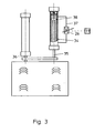
Figur 3- eine Variation des Antriebes der Heizeinrichtung.
- FIG. 1:
- a front view of the device.
- FIG. 2:
- a plan view of the heater and its drive means.
- FIG. 3
- a variation of the drive of the heater.
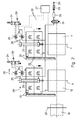
Die Vorrichtung besteht aus einer Formstation 1 mit zwei Spannrahmen 2, 3, von denen der obere Spannrahmen 2 höhenverschiebbar ist und die beide im Zusammenwirken eine Platte 4 oder einen Folienbahnabschnitt aus thermoplastischem Kunststoff einspannen. Über eine Heizeinrichtung 5, angeordnet in der Formstation 1 und/oder in der Beschickungsstation 6, erfolgt die Erwärmung der Platte 4 oder des Folienbahnabschnittes auf Verformungstemperatur. Mittels einer auf dem höhenbeweglichen Formtisch 7 angeordneten Form 8 und durch Anlegen von Vakuum wird die Platte 4 oder der Folienbahnabschnitt zu einem Formteil 9 tiefgezogen. Unterstützt wird das Tiefziehen ggf. durch einen Vorstrecker 10, der mit einer Antriebseinrichtung 11 über eine Kupplung 12 verbunden ist.The device consists of a forming station 1 with two
Seitlich der Formstation 1 ist wahlweise eine Beschickungsstation 6 angeordnet, in die die Platten 4 als Stapel 13 eingelegt werden. Über eine Saugerplatte 14 mit an Vakuum anschließbaren Saugern 15 wird jeweils die oberste Platte 4 des Stapels 13 abgehoben und an die Transporteinrichtung 19 übergeben, die beide Stationen 6, 1 verbindet. Die Vertikalbewegung der Saugerplatte 14 erfolgt über die Antriebseinrichtung 16. Antriebseinrichtung 16 und Saugerplatte 14 sind über die Kupplung 17 verbunden.The side of the forming station 1 is optionally a
Wenn die Vorrichtung nicht vom Plattenstapel 13 arbeitet, sondern Folienbahnabschnitte verformt, wird eine Folienbahn 18 von einer Rolle 21 mittels einer Transporteinrichtung 19 abgezogen, eine Querschneideeinrichtung 20 trennt diese Folienbahnabschnitte ab und die Transporteinrichtung 19 bringt sie in die einzelnen Stationen 6,1.If the device does not work from the
In der Formstation 1 und/oder in der vorgeschalteten Beschickungsstation 6 ist eine Heizeinrichtung 5 angeordnet, die aus einer Oberheizung und ggf. aus einer Unterheizung besteht und generell als Heizeinrichtung 5 bezeichnet wird. Die horizontale Bewegung der Heizeinrichtung 5 zwischen einer Ruheposition 22 und der Heizstellung erfolgt über einen Pneumatikzylinder 23, gesteuert über ein Ventil 24, das von einer Druckluftquelle 29 gespeist wird. In den Zuleitungen 25 zu dem Pneumatikzylinder 23 ist je eine im Querschnitt stufenlos veränderbare Drossel 26 eingebaut, die so gestaltet ist, dass ihr Querschnitt von einer Steuerung 27 aus über eine Steuerleitung 28 verändert werden kann. Beispielsweise kann es sich bei der Drossel 26 um ein Proportionalventil handeln, dessen Querschnitt proportional zur anliegenden Spannung ist.
Jede Heizeinrichtung 5 ist mit einem beliebigen handelsüblichen Wegmeßsystem 30 versehen, mit dem die Lage der Heizeinrichtung 5 festgestellt und über eine Steuerleitung 28 der Steuerung 27 gemeldet wird. Im einfachsten Fall handelt es sich bei diesem Wegmeßsystem 30 um einzelne - vorzugsweise einstellbare - Schalter, die eine bestimmte erreichte Stellung der Heizeinrichtung an die Steuerung 27 melden.In the forming station 1 and / or in the
Each
Beim Verfahren der Heizeinrichtung zwischen Ruheposition 22 und Heizstellung wird nun die Drossel 26 zum Zuführen der Druckluft zur Erzeugung der Bewegung ganz geöffnet, die abluftseitige Drossel 26 zunächst auch. Die Heizeinrichtung 5 verfährt sehr rasch. Bei Annäherung an eine Endlage - Ruheposition bzw. Heizstellung - erfolgt eine Verringerung des Querschnittes vorzugsweise der entsprechenden abluftseitigen Drossel 26 und damit Drosselung der Fahrgeschwindigkeit in der Weise, dass die Bewegung gerade in Endlage zum Stehen kommt, ohne dass ein ruckartiges Abbremsen erfolgt. Eine zusätzliche Veränderung des Querschnittes der zuluftseitigen Drossel 26 ist möglich.When moving the heating device between the
Eine andere Möglichkeit der Drosselung der Fahrbewegung der Heizeinrichtung 5 in Abhängigkeit ihrer Lage ist in Figur 3 dargestellt. Parallel zum Pneumatikzylinder 23 ist ein Dämpfungszylinder 34 mit Kolben 38 angeordnet. Die Kolbenstange 36 des Pneumatikzylinders 23 ist mit der Kolbenstange 35 des Dämpfungszylinder 34 - oder wahlweise auch mit der Heizeinrichtung 5 direkt - verbunden. Der Dämpfungszylinder 34 ist mit Öl gefüllt und das Öl läuft über die Verbindungsleitung 37 zwischen den beiden Zylinderseiten um. In der Verbindungsleitung 37 ist eine Drossel 26 eingebaut, die im Querschnitt durch entsprechende Ansteuerung über die Steuerung 27 verändert werden kann.Another possibility of throttling the travel movement of the
Durch Versuche und eine entsprechende Parametrierung der Steuerung 27 kann man den Zeitpunkt des Beginns der Drosselung und die Geschwindigkeit der Drosselung einmalig durch Versuche ermitteln und in der Steuerung 27 hinterlegen. Man hat auf diese Weise einen optimal schnellen Bewegungsablauf der Heizeinrichtung 5 ohne Gefahr der Beschädigung ihrer Heizelemente.By experiments and a corresponding parameterization of the
Um die Heizeinrichtung 5 im Falle des Energieausfalles in Ruheposition 22 zurückfahren zu können wird in Weiterbildung der Erfindung vorgeschlagen, die Seite des Pneumatikzylinders 23, die zum Fahren in Ruheposition 22 beaufschlagt werden muss, mit einem Durchgangsventil 31 zu verbinden, das mit einem Druckspeicher 32 in Verbindung steht. Dieser Druckspeicher 32 wird über die Druckluftquelle 29 und ein Rückschlagventil 33 gespeist. Im Betrieb der Vorrichtung ist das Durchgangsventil 31 geschlossen, es öffnet bei Energieausfall und verbindet so die eine Seite des Pneumatikzylinders 23 mit dem Druckluftspeicher 32, wodurch das Bewegen der Heizeinrichtung 5 in Ruheposition 22 erfolgt.In order to return the
Claims (2)
- A device for shaping heated plates (4) or film strip sections of thermoplastic polymer by means of differential pressure, consisting of a moulding station (1), a vertically movable moulding table (7) with a mould (8) and a heating apparatus (5) that can be displaced between an idle position and a heating position by means of a pneumatic cylinder (23), characterized by a position measuring system (30) for determining the position of the heating apparatus (5), by a flow restrictor (26) in the supply air and/or exhaust air line of the pneumatic cylinder (23) or in the connecting line (37) between both cylinder sides of a damping cylinder (34) that is arranged parallel to the pneumatic cylinder (23) and the piston rod (35) of which is connected to the piston rod (36) of the pneumatic cylinder (23) or to the heating apparatus (5), and by a control system (27) that varies the cross section of the flow restrictors (26) in dependence on the position of the heating apparatus (5).
- The device according to Claim 1, characterized in that the side of the pneumatic cylinder (23) that, when acted upon, causes the displacement of the heating apparatus (5) into the idle position (22) is connected to a pressure accumulator (32) that is fed by a compressed air source (29) with the aid of a straight-way valve (31), wherein this straight-way valve (31) is closed during the operation of the device and open if an energy loss occurs.
Applications Claiming Priority (2)
| Application Number | Priority Date | Filing Date | Title |
|---|---|---|---|
| DE20315581U DE20315581U1 (en) | 2003-10-10 | 2003-10-10 | Device for deforming heated plates or film web sections made of thermoplastic material |
| DE20315581U | 2003-10-10 |
Publications (2)
| Publication Number | Publication Date |
|---|---|
| EP1522397A1 EP1522397A1 (en) | 2005-04-13 |
| EP1522397B1 true EP1522397B1 (en) | 2007-08-08 |
Family
ID=34202518
Family Applications (1)
| Application Number | Title | Priority Date | Filing Date |
|---|---|---|---|
| EP04023859A Expired - Lifetime EP1522397B1 (en) | 2003-10-10 | 2004-10-07 | Apparatus for shaping heated thermoplastic plates or sheets |
Country Status (4)
| Country | Link |
|---|---|
| EP (1) | EP1522397B1 (en) |
| AT (1) | ATE369242T1 (en) |
| DE (2) | DE20315581U1 (en) |
| ES (1) | ES2291795T3 (en) |
Family Cites Families (5)
| Publication number | Priority date | Publication date | Assignee | Title |
|---|---|---|---|---|
| US3357054A (en) * | 1966-01-04 | 1967-12-12 | Jr Maurice D Hartman | Thermoforming apparatus |
| DE2216651B2 (en) * | 1972-04-07 | 1975-04-10 | Adolf Illig Maschinenbau, 7100 Heilbronn | Heating for heating thermoplastic plastic films or sheets |
| US3787158A (en) * | 1972-07-03 | 1974-01-22 | Koehring Co | Twin sheet thermoformer |
| GB1483454A (en) * | 1974-10-21 | 1977-08-17 | Smith G | Production of plastics articles |
| DE4010441C2 (en) * | 1990-03-31 | 1994-10-20 | Roeder & Spengler Stanz | Device for producing a molded part from a deformable workpiece |
-
2003
- 2003-10-10 DE DE20315581U patent/DE20315581U1/en not_active Expired - Lifetime
-
2004
- 2004-10-07 DE DE502004004554T patent/DE502004004554D1/en not_active Expired - Lifetime
- 2004-10-07 AT AT04023859T patent/ATE369242T1/en not_active IP Right Cessation
- 2004-10-07 ES ES04023859T patent/ES2291795T3/en not_active Expired - Lifetime
- 2004-10-07 EP EP04023859A patent/EP1522397B1/en not_active Expired - Lifetime
Also Published As
| Publication number | Publication date |
|---|---|
| EP1522397A1 (en) | 2005-04-13 |
| ATE369242T1 (en) | 2007-08-15 |
| DE502004004554D1 (en) | 2007-09-20 |
| ES2291795T3 (en) | 2008-03-01 |
| DE20315581U1 (en) | 2005-02-17 |
Similar Documents
| Publication | Publication Date | Title |
|---|---|---|
| EP2952330B1 (en) | Blown film system and method for producing a blown film strip | |
| DE3346628C2 (en) | Device for forming, punching and stacking deep-drawn parts made of thermoplastic material | |
| WO2010043345A1 (en) | Transport means and packaging machine for the width adjustment of film | |
| DE2534486C3 (en) | Method and machine for air pressure forming a thermoplastic resin sheet | |
| EP1880943B1 (en) | Device for sealing a moulded film with cups using a cover film | |
| DE3905767A1 (en) | BOOK FORMING AND PRESSING MACHINE | |
| EP1522397B1 (en) | Apparatus for shaping heated thermoplastic plates or sheets | |
| DE10209650C1 (en) | Adjusting travel of stacking equipment marshaling pressed- and stamped-out thermoplastic vessels, first takes place manually to train production controller | |
| DE4033534C2 (en) | Device for molding, punching and stacking deep-drawn parts made of thermoplastic | |
| EP2052843B1 (en) | Method for operating a device for manufacturing shaped pieces made of thermoplastic material | |
| EP2020305B1 (en) | Device and method for pressing a cover or a stub to a glued spine | |
| DE102006006176B4 (en) | A method of optimizing the cycle time of a thermoforming machine for thermoforming parts from a heated thermoplastic film web | |
| EP1582333B1 (en) | Method and apparatus for thermoforming and cutting out containers from a thermoplastic sheet | |
| EP2660069B1 (en) | Method for operating a quire moulding and pressing machine | |
| US3340574A (en) | Universal forming press | |
| DE3907702C2 (en) | ||
| EP1302303B1 (en) | Apparatus for deforming two plates or film web sections in a forming station | |
| DE2603782C2 (en) | Device for producing a curved molded part from a film section made of thermoplastic material | |
| DE2636463A1 (en) | Machine for vacuum deep-drawing of thermoplastics sheets - comprising mobile and fixed frames, heater, table with mould and vacuum pump | |
| EP2650138A1 (en) | Book moulding and pressing machine | |
| DE2841944B1 (en) | Process to compensate for the expansion in width of a film web made of thermoplastic material by heat and thermoforming machine to carry out the process | |
| DE69424854T2 (en) | Vertical deep-drawing device | |
| DE1166455B (en) | Device for producing hollow bodies from a strip of thermoplastic material | |
| DE102005035859B3 (en) | Deep drawing machine has upper clamping frame for heated plastic sheet with synchronized intermeshing cogs driven by single motor and mounted on ends of short levers whose opposite ends are connected to long levers pivoted on support plate | |
| DE19919038C2 (en) | Process for heating a stretching aid |
Legal Events
| Date | Code | Title | Description |
|---|---|---|---|
| PUAI | Public reference made under article 153(3) epc to a published international application that has entered the european phase |
Free format text: ORIGINAL CODE: 0009012 |
|
| AK | Designated contracting states |
Kind code of ref document: A1 Designated state(s): AT BE BG CH CY CZ DE DK EE ES FI FR GB GR HU IE IT LI LU MC NL PL PT RO SE SI SK TR |
|
| AX | Request for extension of the european patent |
Extension state: AL HR LT LV MK |
|
| 17P | Request for examination filed |
Effective date: 20050329 |
|
| AKX | Designation fees paid |
Designated state(s): AT BE BG CH CY CZ DE DK EE ES FI FR GB GR HU IE IT LI LU MC NL PL PT RO SE SI SK TR |
|
| RAP1 | Party data changed (applicant data changed or rights of an application transferred) |
Owner name: ILLIG MASCHINENBAU GMBH & CO. KG |
|
| 17Q | First examination report despatched |
Effective date: 20061017 |
|
| 17Q | First examination report despatched |
Effective date: 20061017 |
|
| GRAP | Despatch of communication of intention to grant a patent |
Free format text: ORIGINAL CODE: EPIDOSNIGR1 |
|
| GRAS | Grant fee paid |
Free format text: ORIGINAL CODE: EPIDOSNIGR3 |
|
| GRAA | (expected) grant |
Free format text: ORIGINAL CODE: 0009210 |
|
| AK | Designated contracting states |
Kind code of ref document: B1 Designated state(s): AT BE BG CH CY CZ DE DK EE ES FI FR GB GR HU IE IT LI LU MC NL PL PT RO SE SI SK TR |
|
| REG | Reference to a national code |
Ref country code: GB Ref legal event code: FG4D Free format text: NOT ENGLISH |
|
| REG | Reference to a national code |
Ref country code: CH Ref legal event code: EP |
|
| REG | Reference to a national code |
Ref country code: IE Ref legal event code: FG4D Free format text: LANGUAGE OF EP DOCUMENT: GERMAN |
|
| REF | Corresponds to: |
Ref document number: 502004004554 Country of ref document: DE Date of ref document: 20070920 Kind code of ref document: P |
|
| PG25 | Lapsed in a contracting state [announced via postgrant information from national office to epo] |
Ref country code: FI Free format text: LAPSE BECAUSE OF FAILURE TO SUBMIT A TRANSLATION OF THE DESCRIPTION OR TO PAY THE FEE WITHIN THE PRESCRIBED TIME-LIMIT Effective date: 20070808 Ref country code: BG Free format text: LAPSE BECAUSE OF FAILURE TO SUBMIT A TRANSLATION OF THE DESCRIPTION OR TO PAY THE FEE WITHIN THE PRESCRIBED TIME-LIMIT Effective date: 20071108 Ref country code: NL Free format text: LAPSE BECAUSE OF FAILURE TO SUBMIT A TRANSLATION OF THE DESCRIPTION OR TO PAY THE FEE WITHIN THE PRESCRIBED TIME-LIMIT Effective date: 20070808 |
|
| NLV1 | Nl: lapsed or annulled due to failure to fulfill the requirements of art. 29p and 29m of the patents act | ||
| PG25 | Lapsed in a contracting state [announced via postgrant information from national office to epo] |
Ref country code: PL Free format text: LAPSE BECAUSE OF FAILURE TO SUBMIT A TRANSLATION OF THE DESCRIPTION OR TO PAY THE FEE WITHIN THE PRESCRIBED TIME-LIMIT Effective date: 20070808 |
|
| REG | Reference to a national code |
Ref country code: ES Ref legal event code: FG2A Ref document number: 2291795 Country of ref document: ES Kind code of ref document: T3 |
|
| GBV | Gb: ep patent (uk) treated as always having been void in accordance with gb section 77(7)/1977 [no translation filed] |
Effective date: 20070808 |
|
| REG | Reference to a national code |
Ref country code: IE Ref legal event code: FD4D |
|
| EN | Fr: translation not filed | ||
| BERE | Be: lapsed |
Owner name: ILLIG MASCHINENBAU G.M.B.H. & CO. KG Effective date: 20071031 |
|
| PG25 | Lapsed in a contracting state [announced via postgrant information from national office to epo] |
Ref country code: DK Free format text: LAPSE BECAUSE OF FAILURE TO SUBMIT A TRANSLATION OF THE DESCRIPTION OR TO PAY THE FEE WITHIN THE PRESCRIBED TIME-LIMIT Effective date: 20070808 Ref country code: GR Free format text: LAPSE BECAUSE OF FAILURE TO SUBMIT A TRANSLATION OF THE DESCRIPTION OR TO PAY THE FEE WITHIN THE PRESCRIBED TIME-LIMIT Effective date: 20071109 |
|
| PG25 | Lapsed in a contracting state [announced via postgrant information from national office to epo] |
Ref country code: SK Free format text: LAPSE BECAUSE OF FAILURE TO SUBMIT A TRANSLATION OF THE DESCRIPTION OR TO PAY THE FEE WITHIN THE PRESCRIBED TIME-LIMIT Effective date: 20070808 Ref country code: GB Free format text: LAPSE BECAUSE OF FAILURE TO SUBMIT A TRANSLATION OF THE DESCRIPTION OR TO PAY THE FEE WITHIN THE PRESCRIBED TIME-LIMIT Effective date: 20070808 Ref country code: PT Free format text: LAPSE BECAUSE OF FAILURE TO SUBMIT A TRANSLATION OF THE DESCRIPTION OR TO PAY THE FEE WITHIN THE PRESCRIBED TIME-LIMIT Effective date: 20080108 Ref country code: IE Free format text: LAPSE BECAUSE OF FAILURE TO SUBMIT A TRANSLATION OF THE DESCRIPTION OR TO PAY THE FEE WITHIN THE PRESCRIBED TIME-LIMIT Effective date: 20070808 Ref country code: MC Free format text: LAPSE BECAUSE OF NON-PAYMENT OF DUE FEES Effective date: 20071031 Ref country code: CZ Free format text: LAPSE BECAUSE OF FAILURE TO SUBMIT A TRANSLATION OF THE DESCRIPTION OR TO PAY THE FEE WITHIN THE PRESCRIBED TIME-LIMIT Effective date: 20070808 |
|
| PLBE | No opposition filed within time limit |
Free format text: ORIGINAL CODE: 0009261 |
|
| STAA | Information on the status of an ep patent application or granted ep patent |
Free format text: STATUS: NO OPPOSITION FILED WITHIN TIME LIMIT |
|
| PG25 | Lapsed in a contracting state [announced via postgrant information from national office to epo] |
Ref country code: RO Free format text: LAPSE BECAUSE OF FAILURE TO SUBMIT A TRANSLATION OF THE DESCRIPTION OR TO PAY THE FEE WITHIN THE PRESCRIBED TIME-LIMIT Effective date: 20070808 Ref country code: SE Free format text: LAPSE BECAUSE OF FAILURE TO SUBMIT A TRANSLATION OF THE DESCRIPTION OR TO PAY THE FEE WITHIN THE PRESCRIBED TIME-LIMIT Effective date: 20071108 |
|
| 26N | No opposition filed |
Effective date: 20080509 |
|
| PG25 | Lapsed in a contracting state [announced via postgrant information from national office to epo] |
Ref country code: BE Free format text: LAPSE BECAUSE OF NON-PAYMENT OF DUE FEES Effective date: 20071031 |
|
| PG25 | Lapsed in a contracting state [announced via postgrant information from national office to epo] |
Ref country code: EE Free format text: LAPSE BECAUSE OF FAILURE TO SUBMIT A TRANSLATION OF THE DESCRIPTION OR TO PAY THE FEE WITHIN THE PRESCRIBED TIME-LIMIT Effective date: 20070808 |
|
| PG25 | Lapsed in a contracting state [announced via postgrant information from national office to epo] |
Ref country code: AT Free format text: LAPSE BECAUSE OF NON-PAYMENT OF DUE FEES Effective date: 20071007 |
|
| PG25 | Lapsed in a contracting state [announced via postgrant information from national office to epo] |
Ref country code: FR Free format text: LAPSE BECAUSE OF NON-PAYMENT OF DUE FEES Effective date: 20071031 |
|
| REG | Reference to a national code |
Ref country code: CH Ref legal event code: PL |
|
| PG25 | Lapsed in a contracting state [announced via postgrant information from national office to epo] |
Ref country code: SI Free format text: LAPSE BECAUSE OF FAILURE TO SUBMIT A TRANSLATION OF THE DESCRIPTION OR TO PAY THE FEE WITHIN THE PRESCRIBED TIME-LIMIT Effective date: 20070808 |
|
| PG25 | Lapsed in a contracting state [announced via postgrant information from national office to epo] |
Ref country code: CY Free format text: LAPSE BECAUSE OF FAILURE TO SUBMIT A TRANSLATION OF THE DESCRIPTION OR TO PAY THE FEE WITHIN THE PRESCRIBED TIME-LIMIT Effective date: 20070808 |
|
| PG25 | Lapsed in a contracting state [announced via postgrant information from national office to epo] |
Ref country code: LU Free format text: LAPSE BECAUSE OF NON-PAYMENT OF DUE FEES Effective date: 20071007 |
|
| PG25 | Lapsed in a contracting state [announced via postgrant information from national office to epo] |
Ref country code: TR Free format text: LAPSE BECAUSE OF FAILURE TO SUBMIT A TRANSLATION OF THE DESCRIPTION OR TO PAY THE FEE WITHIN THE PRESCRIBED TIME-LIMIT Effective date: 20070808 Ref country code: HU Free format text: LAPSE BECAUSE OF FAILURE TO SUBMIT A TRANSLATION OF THE DESCRIPTION OR TO PAY THE FEE WITHIN THE PRESCRIBED TIME-LIMIT Effective date: 20080209 |
|
| PG25 | Lapsed in a contracting state [announced via postgrant information from national office to epo] |
Ref country code: CH Free format text: LAPSE BECAUSE OF NON-PAYMENT OF DUE FEES Effective date: 20081031 Ref country code: LI Free format text: LAPSE BECAUSE OF NON-PAYMENT OF DUE FEES Effective date: 20081031 |
|
| PGFP | Annual fee paid to national office [announced via postgrant information from national office to epo] |
Ref country code: DE Payment date: 20131021 Year of fee payment: 10 |
|
| PGFP | Annual fee paid to national office [announced via postgrant information from national office to epo] |
Ref country code: ES Payment date: 20131022 Year of fee payment: 10 Ref country code: IT Payment date: 20131030 Year of fee payment: 10 |
|
| REG | Reference to a national code |
Ref country code: DE Ref legal event code: R119 Ref document number: 502004004554 Country of ref document: DE |
|
| PG25 | Lapsed in a contracting state [announced via postgrant information from national office to epo] |
Ref country code: DE Free format text: LAPSE BECAUSE OF NON-PAYMENT OF DUE FEES Effective date: 20150501 |
|
| PG25 | Lapsed in a contracting state [announced via postgrant information from national office to epo] |
Ref country code: IT Free format text: LAPSE BECAUSE OF NON-PAYMENT OF DUE FEES Effective date: 20141007 |
|
| REG | Reference to a national code |
Ref country code: ES Ref legal event code: FD2A Effective date: 20151126 |
|
| PG25 | Lapsed in a contracting state [announced via postgrant information from national office to epo] |
Ref country code: ES Free format text: LAPSE BECAUSE OF NON-PAYMENT OF DUE FEES Effective date: 20141008 |