EP1522293A2 - Transportable power wheelchair - Google Patents
Transportable power wheelchair Download PDFInfo
- Publication number
- EP1522293A2 EP1522293A2 EP04256231A EP04256231A EP1522293A2 EP 1522293 A2 EP1522293 A2 EP 1522293A2 EP 04256231 A EP04256231 A EP 04256231A EP 04256231 A EP04256231 A EP 04256231A EP 1522293 A2 EP1522293 A2 EP 1522293A2
- Authority
- EP
- European Patent Office
- Prior art keywords
- main frame
- assembly
- cross member
- subassemblies
- member assembly
- Prior art date
- Legal status (The legal status is an assumption and is not a legal conclusion. Google has not performed a legal analysis and makes no representation as to the accuracy of the status listed.)
- Withdrawn
Links
- 230000014759 maintenance of location Effects 0.000 claims description 66
- 235000004443 Ricinus communis Nutrition 0.000 claims description 25
- 230000000712 assembly Effects 0.000 claims description 12
- 238000000429 assembly Methods 0.000 claims description 12
- 230000000694 effects Effects 0.000 claims description 7
- 238000003860 storage Methods 0.000 abstract description 4
- 230000007246 mechanism Effects 0.000 description 14
- 210000003811 finger Anatomy 0.000 description 7
- 239000000725 suspension Substances 0.000 description 6
- 239000011295 pitch Substances 0.000 description 4
- 238000010276 construction Methods 0.000 description 3
- 210000003813 thumb Anatomy 0.000 description 3
- 230000001133 acceleration Effects 0.000 description 2
- 230000006978 adaptation Effects 0.000 description 2
- 230000015556 catabolic process Effects 0.000 description 2
- 238000006073 displacement reaction Methods 0.000 description 2
- 238000005516 engineering process Methods 0.000 description 2
- 230000002452 interceptive effect Effects 0.000 description 2
- 230000000284 resting effect Effects 0.000 description 2
- 230000000717 retained effect Effects 0.000 description 2
- OKTJSMMVPCPJKN-UHFFFAOYSA-N Carbon Chemical compound [C] OKTJSMMVPCPJKN-UHFFFAOYSA-N 0.000 description 1
- 230000001154 acute effect Effects 0.000 description 1
- 230000004323 axial length Effects 0.000 description 1
- 230000008901 benefit Effects 0.000 description 1
- 230000009194 climbing Effects 0.000 description 1
- 230000007423 decrease Effects 0.000 description 1
- -1 e.g. Substances 0.000 description 1
- 229920001971 elastomer Polymers 0.000 description 1
- 239000000806 elastomer Substances 0.000 description 1
- 239000003733 fiber-reinforced composite Substances 0.000 description 1
- 239000011152 fibreglass Substances 0.000 description 1
- 229910002804 graphite Inorganic materials 0.000 description 1
- 239000010439 graphite Substances 0.000 description 1
- 230000005484 gravity Effects 0.000 description 1
- 238000003780 insertion Methods 0.000 description 1
- 230000037431 insertion Effects 0.000 description 1
- 238000009434 installation Methods 0.000 description 1
- 230000003993 interaction Effects 0.000 description 1
- 238000004519 manufacturing process Methods 0.000 description 1
- 238000000034 method Methods 0.000 description 1
- 238000012986 modification Methods 0.000 description 1
- 230000004048 modification Effects 0.000 description 1
- 230000002093 peripheral effect Effects 0.000 description 1
- 230000036316 preload Effects 0.000 description 1
- 230000008569 process Effects 0.000 description 1
- 230000002441 reversible effect Effects 0.000 description 1
- 238000005096 rolling process Methods 0.000 description 1
- 238000010408 sweeping Methods 0.000 description 1
- 230000000007 visual effect Effects 0.000 description 1
Images


Classifications
-
- A—HUMAN NECESSITIES
- A61—MEDICAL OR VETERINARY SCIENCE; HYGIENE
- A61G—TRANSPORT, PERSONAL CONVEYANCES, OR ACCOMMODATION SPECIALLY ADAPTED FOR PATIENTS OR DISABLED PERSONS; OPERATING TABLES OR CHAIRS; CHAIRS FOR DENTISTRY; FUNERAL DEVICES
- A61G5/00—Chairs or personal conveyances specially adapted for patients or disabled persons, e.g. wheelchairs
- A61G5/04—Chairs or personal conveyances specially adapted for patients or disabled persons, e.g. wheelchairs motor-driven
- A61G5/041—Chairs or personal conveyances specially adapted for patients or disabled persons, e.g. wheelchairs motor-driven having a specific drive-type
- A61G5/042—Front wheel drive
-
- A—HUMAN NECESSITIES
- A61—MEDICAL OR VETERINARY SCIENCE; HYGIENE
- A61G—TRANSPORT, PERSONAL CONVEYANCES, OR ACCOMMODATION SPECIALLY ADAPTED FOR PATIENTS OR DISABLED PERSONS; OPERATING TABLES OR CHAIRS; CHAIRS FOR DENTISTRY; FUNERAL DEVICES
- A61G5/00—Chairs or personal conveyances specially adapted for patients or disabled persons, e.g. wheelchairs
- A61G5/08—Chairs or personal conveyances specially adapted for patients or disabled persons, e.g. wheelchairs foldable
- A61G5/0875—Chairs or personal conveyances specially adapted for patients or disabled persons, e.g. wheelchairs foldable dismountable, e.g. where the wheelchair can be disassembled for transportation or storage
-
- A—HUMAN NECESSITIES
- A61—MEDICAL OR VETERINARY SCIENCE; HYGIENE
- A61G—TRANSPORT, PERSONAL CONVEYANCES, OR ACCOMMODATION SPECIALLY ADAPTED FOR PATIENTS OR DISABLED PERSONS; OPERATING TABLES OR CHAIRS; CHAIRS FOR DENTISTRY; FUNERAL DEVICES
- A61G5/00—Chairs or personal conveyances specially adapted for patients or disabled persons, e.g. wheelchairs
- A61G5/08—Chairs or personal conveyances specially adapted for patients or disabled persons, e.g. wheelchairs foldable
- A61G5/0891—Chairs or personal conveyances specially adapted for patients or disabled persons, e.g. wheelchairs foldable having rigid supports, e.g. seat or back supports which retain their shape after folding of the wheelchair
-
- A—HUMAN NECESSITIES
- A61—MEDICAL OR VETERINARY SCIENCE; HYGIENE
- A61G—TRANSPORT, PERSONAL CONVEYANCES, OR ACCOMMODATION SPECIALLY ADAPTED FOR PATIENTS OR DISABLED PERSONS; OPERATING TABLES OR CHAIRS; CHAIRS FOR DENTISTRY; FUNERAL DEVICES
- A61G5/00—Chairs or personal conveyances specially adapted for patients or disabled persons, e.g. wheelchairs
- A61G5/10—Parts, details or accessories
- A61G5/1089—Anti-tip devices
-
- H—ELECTRICITY
- H01—ELECTRIC ELEMENTS
- H01M—PROCESSES OR MEANS, e.g. BATTERIES, FOR THE DIRECT CONVERSION OF CHEMICAL ENERGY INTO ELECTRICAL ENERGY
- H01M50/00—Constructional details or processes of manufacture of the non-active parts of electrochemical cells other than fuel cells, e.g. hybrid cells
- H01M50/20—Mountings; Secondary casings or frames; Racks, modules or packs; Suspension devices; Shock absorbers; Transport or carrying devices; Holders
- H01M50/202—Casings or frames around the primary casing of a single cell or a single battery
-
- H—ELECTRICITY
- H01—ELECTRIC ELEMENTS
- H01M—PROCESSES OR MEANS, e.g. BATTERIES, FOR THE DIRECT CONVERSION OF CHEMICAL ENERGY INTO ELECTRICAL ENERGY
- H01M50/00—Constructional details or processes of manufacture of the non-active parts of electrochemical cells other than fuel cells, e.g. hybrid cells
- H01M50/20—Mountings; Secondary casings or frames; Racks, modules or packs; Suspension devices; Shock absorbers; Transport or carrying devices; Holders
- H01M50/244—Secondary casings; Racks; Suspension devices; Carrying devices; Holders characterised by their mounting method
-
- H—ELECTRICITY
- H01—ELECTRIC ELEMENTS
- H01M—PROCESSES OR MEANS, e.g. BATTERIES, FOR THE DIRECT CONVERSION OF CHEMICAL ENERGY INTO ELECTRICAL ENERGY
- H01M50/00—Constructional details or processes of manufacture of the non-active parts of electrochemical cells other than fuel cells, e.g. hybrid cells
- H01M50/20—Mountings; Secondary casings or frames; Racks, modules or packs; Suspension devices; Shock absorbers; Transport or carrying devices; Holders
- H01M50/249—Mountings; Secondary casings or frames; Racks, modules or packs; Suspension devices; Shock absorbers; Transport or carrying devices; Holders specially adapted for aircraft or vehicles, e.g. cars or trains
-
- A—HUMAN NECESSITIES
- A61—MEDICAL OR VETERINARY SCIENCE; HYGIENE
- A61G—TRANSPORT, PERSONAL CONVEYANCES, OR ACCOMMODATION SPECIALLY ADAPTED FOR PATIENTS OR DISABLED PERSONS; OPERATING TABLES OR CHAIRS; CHAIRS FOR DENTISTRY; FUNERAL DEVICES
- A61G5/00—Chairs or personal conveyances specially adapted for patients or disabled persons, e.g. wheelchairs
- A61G5/06—Chairs or personal conveyances specially adapted for patients or disabled persons, e.g. wheelchairs with obstacle mounting facilities, e.g. for climbing stairs, kerbs or steps
-
- A—HUMAN NECESSITIES
- A61—MEDICAL OR VETERINARY SCIENCE; HYGIENE
- A61G—TRANSPORT, PERSONAL CONVEYANCES, OR ACCOMMODATION SPECIALLY ADAPTED FOR PATIENTS OR DISABLED PERSONS; OPERATING TABLES OR CHAIRS; CHAIRS FOR DENTISTRY; FUNERAL DEVICES
- A61G5/00—Chairs or personal conveyances specially adapted for patients or disabled persons, e.g. wheelchairs
- A61G5/10—Parts, details or accessories
- A61G5/1056—Arrangements for adjusting the seat
- A61G5/1075—Arrangements for adjusting the seat tilting the whole seat backwards
-
- Y—GENERAL TAGGING OF NEW TECHNOLOGICAL DEVELOPMENTS; GENERAL TAGGING OF CROSS-SECTIONAL TECHNOLOGIES SPANNING OVER SEVERAL SECTIONS OF THE IPC; TECHNICAL SUBJECTS COVERED BY FORMER USPC CROSS-REFERENCE ART COLLECTIONS [XRACs] AND DIGESTS
- Y02—TECHNOLOGIES OR APPLICATIONS FOR MITIGATION OR ADAPTATION AGAINST CLIMATE CHANGE
- Y02E—REDUCTION OF GREENHOUSE GAS [GHG] EMISSIONS, RELATED TO ENERGY GENERATION, TRANSMISSION OR DISTRIBUTION
- Y02E60/00—Enabling technologies; Technologies with a potential or indirect contribution to GHG emissions mitigation
- Y02E60/10—Energy storage using batteries
-
- Y—GENERAL TAGGING OF NEW TECHNOLOGICAL DEVELOPMENTS; GENERAL TAGGING OF CROSS-SECTIONAL TECHNOLOGIES SPANNING OVER SEVERAL SECTIONS OF THE IPC; TECHNICAL SUBJECTS COVERED BY FORMER USPC CROSS-REFERENCE ART COLLECTIONS [XRACs] AND DIGESTS
- Y10—TECHNICAL SUBJECTS COVERED BY FORMER USPC
- Y10S—TECHNICAL SUBJECTS COVERED BY FORMER USPC CROSS-REFERENCE ART COLLECTIONS [XRACs] AND DIGESTS
- Y10S180/00—Motor vehicles
- Y10S180/907—Motorized wheelchairs
-
- Y—GENERAL TAGGING OF NEW TECHNOLOGICAL DEVELOPMENTS; GENERAL TAGGING OF CROSS-SECTIONAL TECHNOLOGIES SPANNING OVER SEVERAL SECTIONS OF THE IPC; TECHNICAL SUBJECTS COVERED BY FORMER USPC CROSS-REFERENCE ART COLLECTIONS [XRACs] AND DIGESTS
- Y10—TECHNICAL SUBJECTS COVERED BY FORMER USPC
- Y10S—TECHNICAL SUBJECTS COVERED BY FORMER USPC CROSS-REFERENCE ART COLLECTIONS [XRACs] AND DIGESTS
- Y10S297/00—Chairs and seats
- Y10S297/04—Wheelchair
Definitions
- the present invention relates to power wheelchairs, and more particularly to a power wheelchair that facilitates assembly/disassembly for ease of transportation and storage.
- Mid-wheel powered wheelchairs are often designed to position the drive wheels, i.e., the rotational axes thereof, slightly forward of the overall Center Of Gravity (COG) of the occupant and wheelchair to provide enhanced stability and maneuverability. Further, the ability to independently control the speed and torque of each wheel vastly improves the maneuverability, particularly in the yaw axis, of powered wheelchairs. That is, the drive wheels may be driven in opposite directions to enable yaw or heading changes with essentially a zero turn radius. The wheelchair, therefore, can turn within very confined areas and at essentially double the rate.
- Such mid-wheel powered wheelchairs are disclosed in Schaffner et al. U.S. Pat. Nos. 5,944,131 & 6,129,165, both commonly assigned to Pride Mobility Products Corporation of Wales, Pennsylvania.
- Contemporary powered wheelchairs which may include as many as three power supply units (e.g. batteries), a seat, footrest, a main structural frame, drive train assembly other sundry items, can weight several hundred pounds. It will be appreciated, therefore, that even the most physically able individual will require some form of assistance when transporting a powered wheelchair to another destination. In an effort to ameliorate the transportability of such powered wheelchairs, various efforts have been made to augment the lift capacity for the wheelchair user. Perhaps the best known examples are those which are used in combination with a ramp or elevator for rolling or lifting the wheelchair into a vehicle. These "powered-lift systems", as one may readily appreciate, are expensive and are limited in use on vehicles of sufficient size to accommodate the assembled wheelchair and the hydraulic or pneumatic lifting equipment.
- power supply units e.g. batteries
- wheelchairs employ folding frames or removable assemblies in an effort to reduce their weight and/or bulk. As such, these wheelchairs may be stowed and transported in vehicles having a smaller payload capacity. While these wheelchairs have improved the transportability, they typically require the disassembly of multiple components, e.g., fasteners, pins, C-rings, clamps, etc., to yield individual assemblies of appropriate size and/or weight. Alternatively, other designs require the use of special tools to "break-down" or fold the various wheelchair components.
- Kramer, Jr. et al. U.S. Pat. No. 6,220,382 discloses a wheelchair having a separable frame which requires the breakdown of as many as eight separate elements. These designs do not always facilitate rapid disassembly and/or reassembly and, furthermore, create an unwelcome opportunity to misplace, omit, or improperly install smaller assembly items.
- a transportable powered wheelchair which employs a variety of detachable modules to facilitate transportation and storage.
- the powered wheelchair includes a power supply unit, a pair of primary drive wheels, and a drive train subassembly rotatably mounting and independently driving each of the drive wheels.
- the powered wheelchair is further characterized by first and second main frame subassemblies each mounting one of the drive train subassemblies and detachably mounting the power supply unit therebetween.
- At least one cross member assembly connects the main frame subassemblies.
- the cross member is detachably mounted to each of the main frame subassemblies.
- the cross member assembly in combination with the main frame subassemblies, define a main frame assembly having first and second detachable mounts. At least one of the detachable mounts is adapted to accept and pre-position the main frame subassemblies thereby facilitating the attachment of the detachable mount.
- a seat is also detachably mounted to the main frame assembly
- the first detachable mount defines a hinge axis and the cross member assembly is caused to rotate about the hinge axis for attaching the second detachable mount to each of the main frame subassemblies.
- the cross member assembly may complete one or more electrical connections during the physical parts assembly.
- Figure 1 is a perspective view of a transportable powered wheelchair according to the present invention.
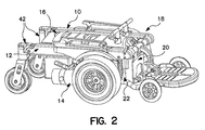
- Figure 2 is an isolated perspective view of the main frame assembly according to the present invention.
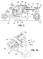
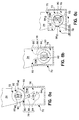
- Figure 3 is a side profile view of one of the main frame subassemblies according to the present invention.
- Figure 3a is an enlarged isolated perspective view of a castor assembly for mounting a rear wheel to an aft end of each main frame subassembly.
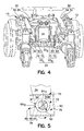
- Figure 4 is an isometric illustration of the cross member assembly from a rear view perspective illustrating the assembly components which define first and second detachable mounts for connecting the cross member assembly to each of the main frame subassemblies.
- Figure 5 depicts a cross sectional view taken substantially along line 5 - 5 of Fig. 4a for revealing the internal details of the first detachable hinge mount which connects the cross member assembly to one of the main frame subassemblies.
- Figure 6a is an isometric illustration of the main frame subassembly with the power supply module removed to reveal details of the second detachable mount including: a handle and a pair of retention blocks for latching the cross member assembly in an upright position.
- Figure 6b is an isometric perspective of the cross member assembly from a rear view projection wherein the handle/retention blocks and a coil spring are exploded from a housing of the cross member assembly.
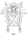
- Figure 7 is a top view of the cross member assembly supporting and pre-positioning each of the main frame subassemblies in an upright position.
- Figures 8a - 8c depict cross sectional views of the hinge mount in various positions during assembly.
- Figures 9a - 9c are broken away side views showing the cross member assembly in various positions relative to one of the main frame subassemblies as it is pivoted into upright therewith.
- Figure 10 is an exploded view of the seat support assembly for detachably mounting a seat to the main frame assembly of the wheelchair.
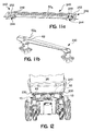
- Figure 11a is an isolated perspective view of a intermediate span bar for detachably mounting the wheelchair seat to the main frame assembly.
- Fig. 11b is an isolated perspective view of a longitudinal support bar for guiding the span bar into engagement with a pair of retaining pins, and functioning as a handle to manipulate and lift a main frame subassembly for transportation and storage.
- Fig. 12 is a rear view of the seat support assembly showing the engagement of the lateral pins with the intermediate span bar.
- Figure 13a depicts a broken away side view of a latching mechanism for retaining a forward channel to a span bar thereby retaining the wheelchair seat.
- Figure 13b is an isolated perspective view of the latching mechanism for retaining the wheelchair seat.
- Figure 13c is a broken away front view of the latching mechanism illustrating the engaged and disengaged positions thereof.
- Figures 14a - 14c depict the power supply unit including the mounting of a pair of battery boxes to a side rail support.
- Fig. 1 depicts a perspective view of an exemplary embodiment of the transportable power wheelchair of the present invention, which is generally referred to by the numeral 2.
- the wheelchair 2 as shown and described herein, is described in the context of a mid-wheel drive powered wheelchair, however, the invention is readily applicable to other powered wheelchair designs/configurations.
- the wheelchair 2 includes several modules and assemblies which may be broken-down into manageable sections for an individual (having normal strength and dexterity) to assemble/disassemble for transport.
- the phrase "manageable sections" means that the various modules, assemblies and/or subassemblies are each under a threshold weight, e.g., under 30 - 50 lbs.
- the disassembly and reassembly thereof is to be performed without the use of special tools.
- the disassembly/reassembly is preferably performed without tools of any kind, i.e., such operations are performed manually or by hand.
- the powered wheelchair 2 comprises first and second main frame subassemblies 10 and 12, respectively, each mounting a drive train subassembly 14 and detachably mounting a power supply unit 16 (best shown in Fig. 2) therebetween.
- At least one cross member assembly 20 connects the main frame subassemblies 10, 12 which, in combination, define a base or main frame assembly 18.
- the load path extends from a point or position on one of the main frame subassemblies through the cross member assembly 20 to a position on the other of the main frame subassemblies.
- the load path also crosses or passes through one of the first or second detachable mounts 22, i.e., between the cross member assembly 20 and each of the main frame subassemblies 10, 12.
- a principle teaching of the invention relates to the adaptation of the cross member assembly 20 and, in particular to the adaptation of one of the detachable mounts 22 to accept and pre-position the main frame subassemblies 10, 12 to facilitate the attachment of the other detachable mount.
- a seat support assembly 200 is adapted to facilitate assembly by several guide channels and/or tracks which forgive misalignment of assembly components. It will be appreciated that misalignment is especially problematic when assembling a seat 28 (Fig. 1) employing a mounting arrangement disposed along the underside thereof.
- a flexible/soft mount castor assembly 42 improves the ride efficacy of the wheelchair 2.
- the invention will first be described in terms of the individual modules and assemblies, which when assembled, produce a structurally-efficient transportable powered wheelchair 2. Subsequently, the discussion will focus on the assembly/disassembly of the wheelchair to gain a better appreciation for the various teachings of the invention. The description is, therefore, organized in the following order: I) Main Frame Subassemblies, II) Cross Member Assembly, III) Seat Support Assembly, IV) Power Supply Support Assembly, and V) Wheelchair Assembly/Disassembly.
- a profile view of the main frame subassembly 12 is depicted along an inwardly facing side, i.e., a side which, when assembled, faces inwardly toward the opposed subassembly.
- the main frame subassembly 12 includes a side frame support 30 having a substantially horizontal upper segment 32, i.e., horizontal relative to a ground plane G P , and a substantially vertical forward segment 34 orthogonal to the upper segment 32.
- the forward segment 34 is mounted to the underside of the upper segment 32, however, the segments 32, 34 may be integrally formed during manufacture of the side frame support 30.
- the upper segment 32 carries one of the drive train subassemblies 14 of the wheelchair propulsion system.
- the drive train subassembly 14 is pivotally mounted to the upper segment 32 about a pivot axis 14 A and independently drives a primary drive wheel 36.
- the powered wheelchair 2 may be easily maneuvered in confined areas, i.e., due to the ability to drive each wheel 36 in opposite directions.
- this drive train/wheel configuration is known as a mid-wheel design and includes a rear caster 40 for supporting the wheelchair 2 on at least three wheels, i.e., the two primary drive wheels 36 and at least one rear castored wheel 40.
- the main frame subassembly 12 preferably includes a rear castor assembly 42 which is pivot mounted to an aft end of the horizontal upper segment 32. More specifically, the castor assembly 42 includes a castor barrel 42 B adapted to support and facilitate rotation of the castor wheel 40 about a vertical axis 40 A . Furthermore, the castor assembly 42 includes an end fitting 44 projecting orthogonally from and relative to the vertical axis 40 A of the castor assembly 42. The pivot axis 44 A of the castor assembly is formed through the end fitting 44 and lies parallel to the wheelchair pitch axis (not shown), i.e., the axis about which the wheelchair 2 pitches forward or aft. Moreover, the castor assembly 42 is spring biased about the pivot axis 44 A such that the castor wheel 40 may be displaced under load in either direction, yet return to a predetermined initial operating position.
- the upper end of the castor barrel 42 B forms a cup-shaped receptacle 46 for accepting one end of a coil spring 48.
- the other end thereof bears against the upper support segment 34 such that the spring axis 48 A is spaced-apart from the pivot axis 44 A of the end fitting 44. Consequently, when an external load is applied to the castor wheel 40, whether vertical or longitudinal (i.e., fore and aft), the wheel may displace about the pivot axis 44 A until the spring force equilibrates the external load.
- the end fitting 44 and coil spring 48 serve as a simple, easily assembled and fabricated, castor wheel suspension.
- the spring force of the individual castor wheel suspension may be adjusted by a lever arm 50 projecting beyond or forwardly of the pivot axis 44 A of the end fitting 44. That is, an adjustment screw (not shown) causes a washer plate 52 to bear against a clevis attachment 53 (Fig. 3) formed at the end of the upper segment 32. As the adjustment screw is turned, the washer plate 52 incrementally changes the rotational position of the end fitting 44 relative to the horizontal upper segment 32, thus defining the initial operating position. As the axial length of the coil spring 48 changes, the preload on the end fitting 44/castor assembly 42 changes. This adjustment capability increases or decreases the spring force required to displace the castor assembly 42 and, consequently, the stiffness of the individual castor wheel suspension.
- the main frame subassembly 12 may also include an Active Anti-Tip System (AATS) 54 having a forward anti-tip wheel 56 mounted to an end of a suspension arm 58.
- AATS Active Anti-Tip System
- the AATS 54 is responsive to accelerations of the wheelchair, i.e., changes to the applied motor torque, to raise or lower the forward anti-tip wheel 56.
- An AATS 54 of the type described herein is more fully described and discussed in commonly-owned U.S. patent 6,129,165.
- the AATS system 54 will not be further discussed herein and the description found in U.S. patent 6,129,165 is incorporated herein by reference in its entirety.
- the main frame subassembly 12 includes various fittings and attachments which connect to other modules of the powered wheelchair 2. These will not be discussed in detail at this time, but merely mentioned to provide a frame of reference for related elements discussed later in the description.
- a circular retention head 90 and a pin connector 136 are disposed in combination with the forward segment 34 and upper segment 32 respectively, of the side frame support 30.
- These attachment fittings are disposed in combination with other fittings of the cross member assembly 20 to create the first and second detachable mounts.
- a lateral pin 62 is disposed in combination with a longitudinal guide/support bar 64.
- a mounting rail 66 is disposed along side the side frame support for detachably mounting the power supply unit 16 (Fig. 2).
- a latching mechanism 68 is disposed in combination with the rail 66 for supporting the power supply unit 16. The latching mechanism 68 is a safety feature which prevents electrical connections from being made until the power supply unit has fully engaged the rail 66.
- the Cross Member (CM) assembly 20 functions to structurally interconnect the main frame subassemblies 10, 12 and facilitates assembly and disassembly of the powered wheelchair 2 by supporting and pre-positioning the main frame subassemblies 10, 12.
- the CM assembly 20 creates one or more load paths extending transversely from one of the side frame supports 30 to the other.
- the load path extends across the CM assembly to identical positions along each of the main frame subassemblies 10, 12.
- the first detachable mount 22 interposes a first load path which structurally interconnects a lower portion (see Fig. 3) of each frame support 30.
- the second detachable mount 24 interposes a second load path which structurally interconnects an upper portion 32 of the frame support 30.
- both of the detachable mounts are either directly or indirectly (through an intermediate structure or component) to the vertical lower segment 34 of the side frame support 30.
- the first detachable mount 22 comprises a pair of pivot mounts 22 R , 22 L disposed on opposite sides of the CM assembly 20.
- Each of the pivot mounts 22 R , 22 L comprise a cup-shaped fitting 70 disposed in combination with the cross member assembly 20 and a retention fitting 72 disposed in combination with one of the main frame subassemblies 10, 12. More specifically, each of the cup-shaped fittings 70 (see Fig. 5) defines an open-ended pocket 76 and a slot 78 disposed through a wall 70W of the fitting 70.
- the slot 78 furthermore, has an first end 80 disposed in register with the open end 82 of the pocket 76, a second end 84 having a substantially circular geometry and a throat region 86 disposed therebetween.
- the throat region 86 defines a throat opening dimension 86 D and the circular slot end 84 defines a slot diameter dimension 84 D .
- the retention fitting 72 comprises a circular retention head 90 and a stationary axle 92 rigidly affixed to and projecting laterally from the vertical support segment 34 of the main frame subassembly 12.
- the axle 92 has a cross sectional configuration which defines a minor diameter 92 MI and a major diameter 92 MA (see Fig. 5) wherein the minor diameter 92 MI corresponds to the longitudinal width (fore and aft) dimension of the axle 92 and the major diameter 92 MA corresponds to the vertical height of the axle 92. Inasmuch as the axle 92 is stationary, such geometric relationships remain constant.
- the pocket 76 of each cup-shaped fitting 70 accepts the circular retention head 90 while the slot 78 accepts the axle 92 of the retention fitting 72.
- the minor diameter thereof must align with or be parallel to the slot axis of symmetry.
- the minor diameter 92 MI of the axle 92 must necessarily be less than the throat opening dimension 86 D and the major diameter 92 MA must be less than the slot end dimension 84 D .
- the throat opening diameter 86 D must be less than the diameter dimension 84 D . This will become evident when discussing the installation and assembly of the CM assembly 20 with each main frame subassembly 10, 12.
- the second detachable mount includes a pair of retention blocks 102, 104 disposed in combination with the cross member assembly 20 and abutment surfaces 106, 108 (in Fig. 4 dashed lead lines indicate a surface under or covered by the retention blocks 102, 104), disposed in combination with each of the main frame subassemblies 10, 12. More specifically, the retention blocks 102, 104 are mounted to a handle 100 which is pivot mounted to the cross member assembly 20.
- the handle 100 has an L-shaped side profile (best seen in Fig.
- the handle 100 is pivotally mounted to each side of the cross member assembly 20. That is, the handle 100 is pivotable about a pivot axis 100 A (shown in Fig. 6a) which is preferably disposed forwardly of an electrical connector 114 disposed in combination with the housing 116 of the cross member assembly 20.
- the handle 100 is spring-biased about its pivot axis 100 A (Fig. 6c) such that a surface of the retention blocks 102, 104 engages the abutment surfaces 106, 108 of the main frame subassemblies 10, 12.
- a coil spring 110 (Figs. 6a and 6c) connects and biases the handle 100 of the cross member assembly 20; however, a torsion or other spring-biasing element, disposed about the pivot axis 100 A , may functionally replace the coil spring 110.
- each of the retention blocks (only one retention block 102 is shown in the figure) have a substantially polygonal profile configuration defining a lead and a locking surface, 112 and 114, respectively. While the lead and locking surfaces 112, 114 are linear in the illustrated embodiment, each may be curvilinear or define a combination of linear and/or curvilinear segments. Generally, the lead surface 112 defines an acute angle relative to a line of tangency about the hinge axis 20 A of the cross member assembly 20. That is, a line tangent to a circle inscribed by the pivot motion of the handle 100 and, more particularly, to a circle inscribed by the rotational motion of the retention blocks 102, 104. The significance of the geometry and angular orientation of the retention blocks 102, 104 will be appreciated when discussing the operation of the handle 100.
- the cross member assembly 20 may structurally support other modules or assemblies and may be directly or indirectly connected to the side frame supports 30 of each of the main frame subassemblies 10, 12.
- a controller or battery charger may be disposed internally of a structural housing 130 for integrating the controller/battery charger with the cross member assembly 20.
- the housing 130 may function to effect the load paths across the cross member assembly 20.
- the cross member assembly 20 may include one or more electrical connectors 134, e.g., a conventional pin connector, for engaging an electrical receptacle 136 (shown in Figs. 6a and 6c) disposed in combination with one or both of the main frame subassemblies 10, 12.
- various electrical connections can be made simultaneously with the attachment of the detachable mounts 22, 24.
- the cross member assembly 20 attaches to the vertical lower segment 30, it should be appreciated that structural elements or components may be disposed between the cross member assembly 20 and the side frame support 30.
- the pin receptacle 136 is mounted to the lower vertical segment 34 and dually functions to provide an electrical connection for the power supply module and an abutment surface 116, 118 for the second detachable mount 24.
- the cross member assembly 20 is laid flat or horizontally (see Fig. 7) for the circular retention head 90 (Fig. 8a) to be received within the pocket 76 of the cup-shaped fitting 70. Further, the axle 92 may slide past the throat region 86 of the slot 78 to the circular slot end 88.
- the pivot mounts 22 R , 22 L function to support the main frame subassemblies 10, 12 in a substantially upright position (Fig. 7). That is, the surface area of engagement between the circular retention head 90 and the cup-shaped fitting 70 is sufficiently large to support and align the subassemblies 10, 12 in the desired upright position.
- the pivot mounts 22 R , 22 L in combination, define a hinge axis 22 A (see Fig. 7) about which the cross member assembly 20 may rotate.
- Figs. 9a through 9c depict the operational displacement of the handle 100 and one of the retention blocks 102 as it engages and disengages the abutment surface 106.
- the cross member assembly 20 lies horizontally such that the circular retention head 90 of a main frame subassembly 12 is received within the cup-shaped fitting 70.
- the axle 92 of the retention head 90 slides past the throat region of the slot 78 in one orientation, and is captured therein when oriented in a second position.
- the cup-shaped fitting 70 releases the retention head 90 when the slot 78 is substantially vertical (as shown in Fig. 9a) and captures the retention head 90 when the slot 78 (as seen in Fig. 9c) is horizontal or orthogonal to the vertical.
- the cross member assembly 20 is shown in various angular positions to reveal the motion of the handle and structural interaction of the retention block 102 with the main frame subassembly 12, and more particularly, with a pin connector 116.
- the cross member assembly 20 rotates in a clockwise direction, i.e., in the direction of arrow R 20 , about pivot axis 20 A .
- the guide surface 112 contacts the comer of the pin connector 116, thereby lifting the handle 100 vertically (i.e., rotating the handle 100 counter-clockwise).
- the retention block 102 slides over the top surface of the pin connector 136 until reaching the opposite comer or end of the connector 136, i.e., at the noon or (12 th ) hour position denoted by arrow 1200.
- the coil spring 110 (shown in Fig. 9c) causes the handle 100 to rotate in a clockwise direction as the retention block 102 passes the pin connector.
- the locking surface 114 of the retention block 102 engages the abutment surface 106 to retain the cross member assembly 20 in a vertical position.
- both retention blocks 102, 104 simultaneously engage both of the abutment surfaces 106, 108. That is, the cross member assembly 20 is retained on both sides of its housing 130 against adjacent pin connectors 136.
- Disengagement of the handle 100 and retention blocks 102, 104 is performed by reversing the operation described above. Consequently, the spring biased handle 100, retention blocks 102, 104 and retention surfaces 106, 108 may alternatively form the second detachable mount 22. Furthermore, complete rotation (see Fig. 8b) of the cup-shaped fitting 70 captures the axle 92 as a result of the orientation of the fitting 70 relative to the axle 92, i.e., the larger major diameter 92 MA of the axle 92 cannot pass the throat region 86 of the slot 78.
- cylindrical resilient bearings 160 may engage C-shaped seating surfaces 164 disposed at the forward end of each side frame support 30.
- the bumpers 160 are cylindrical and provide a soft or resilient seating surface so that additional spring force may be applied to the second detachable mount 24. Additionally, the soft mount also serves to maintain the lateral and vertical position of the cross member assembly 20 relative to each of the main frame subassemblies 10, 12.
- the handle 100 and retention blocks 102, 104 may be positively retained by the relative position of other wheelchair components.
- battery boxes 302a, 302b may be positioned proximal to the handle 100 so as to prevent its rotation and release of the cross member assembly 20 until the boxes 302a, 302b are disassembled. The assembly and disassembly of the power supply module will be discussed hereinafter.
- the seat support assembly 200 is detachably mounted to the main frame assembly 18 of the powered wheelchair 2.
- the seat support assembly 200 comprises a trapeze bar assembly 202 supporting a forward portion of the seat 28 and a pivot mount assembly 206 supporting an aft portion of the seat 28.
- the forward trapeze bar assembly 202 includes a channel 204 disposed in combination with the underside 28 U of the seat 28 and a span bar 208 disposed in combination with the main frame assembly 18.
- the channel 204 extends laterally from one side of the seat 28 to the other, has a substantially inverted J-shaped cross sectional configuration, and has an opening 210 facing downwardly for engaging the span bar 208.
- the span bar 208 comprises a laterally extending bar 212 supported by a pair of vertical stanchions 214a, 214b. Together the bar 212 and vertical stanchions 214a, 214b define a substantially double-T profile configuration, however, a variety of profile configurations may be employed including a U- or L-shaped configuration.
- the span bar 208 is disposed in combination with the cross member assembly 20.
- the vertical stanchions 214a, 214b fit into mounting sleeves 220 (see Fig. 10) and may be adjustable vertically to raise or lower the forward portion 28 F of the seat 28.
- the span bar 208 may be used as a handle for rotating the cross member assembly 20 during assembly and disassembly. This also provides a convenient means for carrying the cross member assembly 20 during transport of the wheelchair 2.
- the pivot mount assembly 206 includes, inter alia, a channel assembly 208 disposed in combination with the underside 28 U of the seat 28 aft of the trapeze bar assembly 202 and, furthermore, is adapted to facilitate pivot motion of the seat 28 about a transverse pivot axis, i.e., an axis parallel to the pitch axis (not shown) of the wheelchair.
- the pivot mount assembly 206 includes a pair of lateral pins 62 each disposed in combination with the horizontal upper segment 32 of one of the main frame subassemblies 10, 12. More specifically, the lateral pins 62 are each disposed in combination with a longitudinal support bar 230 which is mounted to the side frame support 30 of a respective main frame subassembly.
- the longitudinal support bar 230 which is disposed substantially parallel to and co-planar with the horizontal upper segment 32 of the side frame support 30, serves two principle functions.
- a first is the support of the seat, most especially, to align the underside of the seat 28 with the lateral pins 62. It will be appreciated that with pivot mounting assembly 206 being disposed its underside, assembly and disassembly must essentially be performed by tactile rather than visual feedback. Consequently, the longitudinal support bars 230 seat within a groove or track of the seat and guided onto the pins 62. This will be discussed in greater detail in the subsequent paragraphs.
- the support bars 230 function as a handle for manipulating and lifting each of the main frame subassemblies 10, 12 during assembly and disassembly. Consequently, a dedicated handle, i.e., in addition to a seat supporting/guiding bar, is not required.
- the pivot mounting assembly 206 also includes a channel 236 (Fig. 10 only) disposed in combination with the underside 28 U of the seat 28 and an interface bar 240 having end fittings 242 for engaging the lateral pins 62. More specifically, the channel 236 extends laterally across the underside 28 U of the seat, has a substantially C-shaped cross sectional configuration and has an opening 246 (see Fig. 10) facing rearwardly.
- the interface bar or intermediate span bar 240 has a cross-sectional configuration which may be accepted internally of the channel 236, a pair of grooves 244 proximal to each end for accepting and sliding along the upper surface of the longitudinal support bar 230 and a pair of tracks 248 for accepting the lateral pins 62 disposed through the support bar 230.
- the tracks 248 have an open end 252 facing rearwardly for accepting the lateral pins 62 and, when fully engaged permit a limited degree of pivotal motion about the pivot axis 62 A of the lateral pins 62.
- the longitudinal support bar 230 rides in the channels or grooves 244 of the intermediate span bar 240 to guide the lateral pins 62 into engagement. While the pins 62 are shown to extend through the longitudinal support bar, it will be appreciated that the pins 62 need only extend or project from on side of the support to effect the necessary pivot displacement. That is, assembly and disassembly requires a small degree of pivot motion to enable to forward channel 204 to sit upon the forward span bar 206.
- the latching mechanism 280 is affixed to the forward channel 204 for maintaining the position of the span bar 208. More specifically, the latching mechanism 280 includes a mounting plate 282 (Figs. 13a - 13c) affixed to a negatively sloping face surface of 284 (Fig. 13a) of the forward channel 204. Retention fingers 286a, 286b are pivotally mounted to the base plate 282 and project downwardly and rearwardly to partially close the channel opening 210.
- the fingers 286a, 286b are torsionally-biased to a fully-extended position by means of a torsion spring 288 (only the ends are visible in Figs. 13b and 13c). Further, the fully-extended position is shown in solid lines in Fig. 13c.
- the retention fingers 286a, 286b are held in the fully-extended position by a Y-shaped block 290 which abuts a pair of thumb release handles 292.
- the block 290 is pivotally mounted to a bracket 294 of the latch plate 282 and may be rotated to a "stop" or "release” position.
- Fig. 13a shows the stop position of the block 290 in solid lines and the release position in phantom or dashed lines. Further, the block 290 has been omitted from Fig. 13c to more clearly illustrate the "release" position of the retention fingers 286a, 286b.
- a power supply unit 16 for providing power to the wheelchair 2 detachably mounts to each of the main frame subassemblies 10, 12.
- the power supply unit 16 comprises two battery boxes 302a, 302b for housing two DC batteries (not shown).
- Each of the battery boxes 302a, 302b have flanges 304 projecting laterally to each side of the boxes 302a, 302b and each flange 304 thereof includes a runner 308 along its peripheral edge.
- the runners 308 slidably engage rails 310 which mount to the main frame subassemblies 10, 12. More specifically, each rail 310 is disposed in combination with the upper support segment 32 of each of the main frame subassemblies 10, 12.
- the rails 310 are generally parallel and adapted in length to receive two battery boxes 302a, 302b in tandem.
- Each of the battery boxes 302a, 302b are slid longitudinally into the rails 310 and have intermediate connectors 312b disposed between the boxes to electrically connect the battery boxes 302a, 302b. Furthermore, connectors 312a (see Fig. 7) may be employed should the cross member assembly 20 be integrated with a controller or battery charger. Handles 313a, 313b are provided along the upper surface of the battery boxes 302a, 302b to facilitate lifting and manipulation as the boxes 302a, 302b are slid into or out of the rails 310. In Fig.
- a retention pin 318 projects upwardly into the channel 320 of the rail 310 to ensure that the power supply unit 16 will not inadvertently slide rearwardly out of engagement, i.e., upon an acceleration of the powered wheelchair 2. That is, the retention pin 318 may be recessed into an aperture against the biasing force of a spring (not shown) when the weight of the battery box 302, i.e., as applied by the rail thereof, urges the pin 318 downwardly. When the battery box 302 has passed the retention pin 318 in the channel 320, the biasing force of the spring causes the retention pin 318 to project upwardly into the channel 320.
- a further safety feature is provided by a latching mechanism 322 which is disposed in combination with the retention pin 318.
- the latching mechanism 322 which is operable to prohibit electrical connectivity between the plug 314 and receptacle 316 until the runner has fully engaged the rail 310, i.e., slid past the retention pin 318. More specifically, the latching mechanism employs a lever 324 to interfere with the plug/receptacle engagement when the battery boxes 302a, 302b are not fully engaged.
- the lever 324 rotates downwardly to block the insertion of the plug 314 into the receptacle 316 when the retention pin 318 is recessed, i.e., when the weight of the battery box 302b is on the retention pin, and, consequently, not fully engaged.
- the lever 324 may only be removed or rotated to a non-interfering position when the retention pin 318 is fully extended, i.e., when the rail 308 has passed the retention pin and the weight of the box 302b is not acting on the pin 308.
- a single latch mechanism 322, along one of the rails 310 is employed to avoid the complexities and cost of redundant latch mechanisms.
- the transportable wheelchair 2 is assembled by first laying the cross member assembly 20 flat or horizontally on the ground.
- the main frame assemblies 10, 12 are positioned upright to engage the cross member assembly 20 by effecting the first detachable mount 22.
- the mount 22 is capable of maintaining the relative position of the subassemblies 10, 12.
- the cross member assembly 20 is then rotated to effect engagement of the second detachable mount 22 while, in one embodiment of the invention, simultaneously effecting engagement of one or more electrical connectors (see Fig. 9).
- the battery boxes 302a, 302b are slid forwardly into engagement with the rails 310 until the retention pin 318 (Fig.
- the seat 28 is laid upon the longitudinal support bars 230 such that the grooves 242 of the interface bar 240 may slide forward and aft.
- the seat is pivoted upwardly and slid rearwardly causing the lateral pins 62 engage the track 244 of the interface bar 248.
- the seat 28 is pivoted downwardly so that the channel 204 sits upon an span bar 208.
- the latching mechanism 280 must be open to allow the forward channel 204 to engage the span bar 208 as the seat 16 is set vertically downward.
- the thumb release handles 292 are released to allow the torsionally-biased fingers 286a, 286b to close the opening 210 of the forward channel 204.
- the disassembly of the powered wheelchair 2 is essentially the reverse of the foregoing assembly steps and, in the interest of brevity, will not be reiterated herein.
- the various assembly/disassembly steps may be arranged in a different order, depending upon the clearance provided between elements.
- the battery boxes may be installed before or after the seat has been attached to the main frame assembly 18.
- the transportable powered wheelchair of the present invention is modularized to separate the wheelchair into manageable sections or modules. That is, the powered wheelchair comprises only five modules, i.e., two main frame subassemblies, a cross member assembly and two (2) battery boxes, which define the power supply unit.
- the assembly process. is facilitated by first and second detachable mounts 22, 24 for connecting the cross member assembly to each of the main frame subassemblies 10, 12. That is, the first detachable mount 22 functions to spatially position and support the main frame subassemblies 10, 12, i.e., in an upright position.
- first detachable mount 22 maintains such pre-positioning to permit the attachment of the second detachable mount 24 to structurally interconnect the subassemblies 10, 12 at two positions.
- the detachable mounts are also spaced-apart to structurally augment the main frame assembly 18.
- the cross member assembly 20 may function to facilitate electrical connections between the power supply unit 12 and the electrical systems employed on the powered wheelchair 2. That is, the electrical connections are made simultaneously as the second detachable mount 24 is made.
- the cross member assembly 20 may structurally support other systems to integrate such modules and reduce the number of assemblies to be connected.
- the cross member assembly is configured to permit handling and attachment by a simple rotational motion which negates the need for two or more persons to assemble/disassemble the powered wheelchair.
- the cross member assembly may further produce or provide a support for the seat assembly. This is, the cross member assembly may support the trapeze bar assembly.
- the abutment surfaces 106, 108 are disposed in combination with the pin connectors 136, i.e., along the back side surface of each of the connectors 136.
- any surface disposed in combination with one or both of the main frame subassemblies 10, 12 which is capable of reacting a substantially horizontal load or load component may be employed.
- the batteries 302a, 320b are shown as having a runner disposed in combination with a rail, other detachable mounting schemes may be employed.
- the battery boxes may include J-hooks for being hung upon a longitudinal rod disposed along the side frame supports of the main frame subassemblies.
- a footrest assembly may be incorporated as an option, and, therefore, may be disposed in combination with the cross member assembly.
Landscapes
- General Health & Medical Sciences (AREA)
- Animal Behavior & Ethology (AREA)
- Life Sciences & Earth Sciences (AREA)
- Veterinary Medicine (AREA)
- Health & Medical Sciences (AREA)
- Public Health (AREA)
- Electrochemistry (AREA)
- General Chemical & Material Sciences (AREA)
- Chemical Kinetics & Catalysis (AREA)
- Chemical & Material Sciences (AREA)
- Aviation & Aerospace Engineering (AREA)
- Engineering & Computer Science (AREA)
- Handcart (AREA)
- Carriages For Children, Sleds, And Other Hand-Operated Vehicles (AREA)
Abstract
Description
- The present invention relates to power wheelchairs, and more particularly to a power wheelchair that facilitates assembly/disassembly for ease of transportation and storage.
- Self-propelled or powered wheelchairs have vastly improved the mobility/transportability of the disabled and/or handicapped. Whereas in the past, disabled/handicapped individuals were nearly entirely reliant upon the assistance of others for transportation, the Americans with Disabilities Act (ADA) of June 1990 has effected sweeping changes to provide equal access and freedom of movement/mobility for disabled individuals. Notably, various structural changes have been mandated to the construction of homes, offices, entrances, sidewalks, and even parkway/river crossing, e.g., bridges, to include enlarged entrances, powered doorways, entrance ramps, curb ramps, etc., to ease mobility for disabled persons in and around society.
- Along with these societal changes has come an opportunity to offer better, more agile, longer-running and/or more stable powered wheelchairs to take full advantage of the new freedoms mandated by the ADA. More specifically, various technologies, initially developed for the automobile and aircraft industries, are being successfully applied to powered wheelchairs to enhance the ease of control, improve stability, and/or reduce wheelchair weight and bulk. For example, sidearm controllers, i.e., multi-axis joysticks, employed in high technology VTOL and fighter aircraft, are being utilized for controlling the speed and direction of powered wheelchairs. Innovations made in the design of automobile suspension systems, e.g., active suspension systems, which vary spring stiffness to vary ride efficacy, have also been adapted to wheelchairs to improve and stabilize powered wheelchairs. Other examples include the use of high-strength fiber reinforced composites, e.g., graphite, fiberglass, etc., to improve the strength of the wheelchair frame while reducing weight and bulk.
- One particular system which has gained widespread popularity/acceptance is mid-wheel drive powered wheelchairs, and more particularly, such powered wheelchairs with independently driven and controlled drive wheels. Mid-wheel powered wheelchairs are often designed to position the drive wheels, i.e., the rotational axes thereof, slightly forward of the overall Center Of Gravity (COG) of the occupant and wheelchair to provide enhanced stability and maneuverability. Further, the ability to independently control the speed and torque of each wheel vastly improves the maneuverability, particularly in the yaw axis, of powered wheelchairs. That is, the drive wheels may be driven in opposite directions to enable yaw or heading changes with essentially a zero turn radius. The wheelchair, therefore, can turn within very confined areas and at essentially double the rate. Such mid-wheel powered wheelchairs are disclosed in Schaffner et al. U.S. Pat. Nos. 5,944,131 & 6,129,165, both commonly assigned to Pride Mobility Products Corporation of Exeter, Pennsylvania.
- While such wheelchair designs have vastly improved the capability and stability of powered wheelchairs, designers thereof are continually being challenged to examine and improve wheelchair design and construction. While these are all welcome advances, they also necessarily add weight and complexity to the vehicle.
- Contemporary powered wheelchairs, which may include as many as three power supply units (e.g. batteries), a seat, footrest, a main structural frame, drive train assembly other sundry items, can weight several hundred pounds. It will be appreciated, therefore, that even the most physically able individual will require some form of assistance when transporting a powered wheelchair to another destination. In an effort to ameliorate the transportability of such powered wheelchairs, various efforts have been made to augment the lift capacity for the wheelchair user. Perhaps the best known examples are those which are used in combination with a ramp or elevator for rolling or lifting the wheelchair into a vehicle. These "powered-lift systems", as one may readily appreciate, are expensive and are limited in use on vehicles of sufficient size to accommodate the assembled wheelchair and the hydraulic or pneumatic lifting equipment.
- Other wheelchairs employ folding frames or removable assemblies in an effort to reduce their weight and/or bulk. As such, these wheelchairs may be stowed and transported in vehicles having a smaller payload capacity. While these wheelchairs have improved the transportability, they typically require the disassembly of multiple components, e.g., fasteners, pins, C-rings, clamps, etc., to yield individual assemblies of appropriate size and/or weight. Alternatively, other designs require the use of special tools to "break-down" or fold the various wheelchair components.
- Kramer, Jr. et al. (U.S. Pat. No. 6,220,382) discloses a wheelchair having a separable frame which requires the breakdown of as many as eight separate elements. These designs do not always facilitate rapid disassembly and/or reassembly and, furthermore, create an unwelcome opportunity to misplace, omit, or improperly install smaller assembly items.
- A need, therefore, exists to provide a transportable wheelchair which (i) permits assembly and disassembly in a rapid and expeditious fashion, (ii) minimizes the number of assemblies, (iii) eliminates the potential for omission of smaller parts or improper reassembly, and (iv) enhances the ability to handle/manipulate subassemblies.
- A transportable powered wheelchair is provided which employs a variety of detachable modules to facilitate transportation and storage. The powered wheelchair includes a power supply unit, a pair of primary drive wheels, and a drive train subassembly rotatably mounting and independently driving each of the drive wheels. The powered wheelchair is further characterized by first and second main frame subassemblies each mounting one of the drive train subassemblies and detachably mounting the power supply unit therebetween. At least one cross member assembly connects the main frame subassemblies. The cross member is detachably mounted to each of the main frame subassemblies. The cross member assembly, in combination with the main frame subassemblies, define a main frame assembly having first and second detachable mounts. At least one of the detachable mounts is adapted to accept and pre-position the main frame subassemblies thereby facilitating the attachment of the detachable mount. A seat is also detachably mounted to the main frame assembly.
- In one embodiment of the invention, the first detachable mount defines a hinge axis and the cross member assembly is caused to rotate about the hinge axis for attaching the second detachable mount to each of the main frame subassemblies. Further, the cross member assembly may complete one or more electrical connections during the physical parts assembly.
- For the purpose of illustrating the invention, there is shown in the drawings various forms that are presently preferred; it being understood, however, that this invention is not limited to the precise arrangements and constructions particularly shown.
- Figure 1 is a perspective view of a transportable powered wheelchair according to the present invention.
- Figure 2 is an isolated perspective view of the main frame assembly according to the present invention.
- Figure 3 is a side profile view of one of the main frame subassemblies according to the present invention.
- Figure 3a is an enlarged isolated perspective view of a castor assembly for mounting a rear wheel to an aft end of each main frame subassembly.
- Figure 4 is an isometric illustration of the cross member assembly from a rear view perspective illustrating the assembly components which define first and second detachable mounts for connecting the cross member assembly to each of the main frame subassemblies.
- Figure 5 depicts a cross sectional view taken substantially along line 5 - 5 of Fig. 4a for revealing the internal details of the first detachable hinge mount which connects the cross member assembly to one of the main frame subassemblies.
- Figure 6a is an isometric illustration of the main frame subassembly with the power supply module removed to reveal details of the second detachable mount including: a handle and a pair of retention blocks for latching the cross member assembly in an upright position.
- Figure 6b is an isometric perspective of the cross member assembly from a rear view projection wherein the handle/retention blocks and a coil spring are exploded from a housing of the cross member assembly.
- Figure 7 is a top view of the cross member assembly supporting and pre-positioning each of the main frame subassemblies in an upright position.
- Figures 8a - 8c depict cross sectional views of the hinge mount in various positions during assembly.
- Figures 9a - 9c are broken away side views showing the cross member assembly in various positions relative to one of the main frame subassemblies as it is pivoted into upright therewith.
- Figure 10 is an exploded view of the seat support assembly for detachably mounting a seat to the main frame assembly of the wheelchair.
- Figure 11a is an isolated perspective view of a intermediate span bar for detachably mounting the wheelchair seat to the main frame assembly.
- Fig. 11b is an isolated perspective view of a longitudinal support bar for guiding the span bar into engagement with a pair of retaining pins, and functioning as a handle to manipulate and lift a main frame subassembly for transportation and storage.
- Fig. 12 is a rear view of the seat support assembly showing the engagement of the lateral pins with the intermediate span bar.
- Figure 13a depicts a broken away side view of a latching mechanism for retaining a forward channel to a span bar thereby retaining the wheelchair seat.
- Figure 13b is an isolated perspective view of the latching mechanism for retaining the wheelchair seat.
- Figure 13c is a broken away front view of the latching mechanism illustrating the engaged and disengaged positions thereof.
- Figures 14a - 14c depict the power supply unit including the mounting of a pair of battery boxes to a side rail support.
- Referring now to the drawings wherein like reference numerals identify like elements, components, subassemblies etc., Fig. 1 depicts a perspective view of an exemplary embodiment of the transportable power wheelchair of the present invention, which is generally referred to by the
numeral 2. Thewheelchair 2, as shown and described herein, is described in the context of a mid-wheel drive powered wheelchair, however, the invention is readily applicable to other powered wheelchair designs/configurations. - The
wheelchair 2 includes several modules and assemblies which may be broken-down into manageable sections for an individual (having normal strength and dexterity) to assemble/disassemble for transport. The phrase "manageable sections" means that the various modules, assemblies and/or subassemblies are each under a threshold weight, e.g., under 30 - 50 lbs. In addition to the modularization of thepowered wheelchair 2, the disassembly and reassembly thereof is to be performed without the use of special tools. In fact, the disassembly/reassembly is preferably performed without tools of any kind, i.e., such operations are performed manually or by hand. - In the broadest sense of the invention, and referring to Figs. 1 and 2, the
powered wheelchair 2 comprises first and secondmain frame subassemblies drive train subassembly 14 and detachably mounting a power supply unit 16 (best shown in Fig. 2) therebetween. At least onecross member assembly 20 connects themain frame subassemblies main frame assembly 18. Thecross member assembly 20, in combination with themain frame subassemblies detachable mount 22 is visible, inasmuch as second detachable mount is disposed on the opposite side of thecross member assembly 20. Other configurations are contemplated, such as that described in commonly owned co-pending patent application entitled "Transportable Wheelchair." The load path extends from a point or position on one of the main frame subassemblies through thecross member assembly 20 to a position on the other of the main frame subassemblies. The load path also crosses or passes through one of the first or seconddetachable mounts 22, i.e., between thecross member assembly 20 and each of themain frame subassemblies powered wheelchair 2. - A principle teaching of the invention relates to the adaptation of the
cross member assembly 20 and, in particular to the adaptation of one of thedetachable mounts 22 to accept and pre-position themain frame subassemblies wheelchair 2. - The invention will first be described in terms of the individual modules and assemblies, which when assembled, produce a structurally-efficient transportable
powered wheelchair 2. Subsequently, the discussion will focus on the assembly/disassembly of the wheelchair to gain a better appreciation for the various teachings of the invention. The description is, therefore, organized in the following order: I) Main Frame Subassemblies, II) Cross Member Assembly, III) Seat Support Assembly, IV) Power Supply Support Assembly, and V) Wheelchair Assembly/Disassembly. - Inasmuch as the
main frame subassemblies subassemblies 12 will be described in detail. In Fig. 3, a profile view of themain frame subassembly 12 is depicted along an inwardly facing side, i.e., a side which, when assembled, faces inwardly toward the opposed subassembly. Themain frame subassembly 12 includes aside frame support 30 having a substantially horizontalupper segment 32, i.e., horizontal relative to a ground plane GP, and a substantiallyvertical forward segment 34 orthogonal to theupper segment 32. In the described embodiment theforward segment 34 is mounted to the underside of theupper segment 32, however, thesegments side frame support 30. Theupper segment 32 carries one of thedrive train subassemblies 14 of the wheelchair propulsion system. Thedrive train subassembly 14 is pivotally mounted to theupper segment 32 about apivot axis 14A and independently drives aprimary drive wheel 36. Inasmuch as each of theprimary drive wheels 36 is independently driven, thepowered wheelchair 2 may be easily maneuvered in confined areas, i.e., due to the ability to drive eachwheel 36 in opposite directions. As mentioned earlier, this drive train/wheel configuration is known as a mid-wheel design and includes arear caster 40 for supporting thewheelchair 2 on at least three wheels, i.e., the twoprimary drive wheels 36 and at least one rearcastored wheel 40. - In Figs. 3 and 3a, the
main frame subassembly 12 preferably includes arear castor assembly 42 which is pivot mounted to an aft end of the horizontalupper segment 32. More specifically, thecastor assembly 42 includes acastor barrel 42B adapted to support and facilitate rotation of thecastor wheel 40 about avertical axis 40A. Furthermore, thecastor assembly 42 includes an end fitting 44 projecting orthogonally from and relative to thevertical axis 40A of thecastor assembly 42. Thepivot axis 44A of the castor assembly is formed through the end fitting 44 and lies parallel to the wheelchair pitch axis (not shown), i.e., the axis about which thewheelchair 2 pitches forward or aft. Moreover, thecastor assembly 42 is spring biased about thepivot axis 44A such that thecastor wheel 40 may be displaced under load in either direction, yet return to a predetermined initial operating position. - In the preferred embodiment, the upper end of the
castor barrel 42B, or the end fitting 44, forms a cup-shapedreceptacle 46 for accepting one end of acoil spring 48. The other end thereof bears against theupper support segment 34 such that thespring axis 48A is spaced-apart from thepivot axis 44A of the end fitting 44. Consequently, when an external load is applied to thecastor wheel 40, whether vertical or longitudinal (i.e., fore and aft), the wheel may displace about thepivot axis 44A until the spring force equilibrates the external load. As such, the end fitting 44 andcoil spring 48 serve as a simple, easily assembled and fabricated, castor wheel suspension. - The spring force of the individual castor wheel suspension may be adjusted by a
lever arm 50 projecting beyond or forwardly of thepivot axis 44A of the end fitting 44. That is, an adjustment screw (not shown) causes awasher plate 52 to bear against a clevis attachment 53 (Fig. 3) formed at the end of theupper segment 32. As the adjustment screw is turned, thewasher plate 52 incrementally changes the rotational position of the end fitting 44 relative to the horizontalupper segment 32, thus defining the initial operating position. As the axial length of thecoil spring 48 changes, the preload on the end fitting 44/castor assembly 42 changes. This adjustment capability increases or decreases the spring force required to displace thecastor assembly 42 and, consequently, the stiffness of the individual castor wheel suspension. - In Fig. 3, the
main frame subassembly 12 may also include an Active Anti-Tip System (AATS) 54 having aforward anti-tip wheel 56 mounted to an end of asuspension arm 58. Briefly, theAATS 54 is responsive to accelerations of the wheelchair, i.e., changes to the applied motor torque, to raise or lower theforward anti-tip wheel 56. By raising theanti-tip wheel 56, the curb climbing ability of thewheelchair 2 is improved and, by lowering theanti-tip wheel 56, the pitch stability of thewheelchair 2 is enhanced. AnAATS 54 of the type described herein, is more fully described and discussed in commonly-owned U.S. patent 6,129,165. For the purposes of clarity and conciseness, theAATS system 54 will not be further discussed herein and the description found in U.S. patent 6,129,165 is incorporated herein by reference in its entirety. - The
main frame subassembly 12 includes various fittings and attachments which connect to other modules of thepowered wheelchair 2. These will not be discussed in detail at this time, but merely mentioned to provide a frame of reference for related elements discussed later in the description. For example, acircular retention head 90 and apin connector 136 are disposed in combination with theforward segment 34 andupper segment 32 respectively, of theside frame support 30. These attachment fittings are disposed in combination with other fittings of thecross member assembly 20 to create the first and second detachable mounts. Further, alateral pin 62 is disposed in combination with a longitudinal guide/support bar 64. The structure and function of thelateral pin 62 will be discussed later, however, suffice it to say at this juncture that thepin 62 andlongitudinal support bar 64 detachably supports the wheelchair seat. Similarly, a mountingrail 66 is disposed along side the side frame support for detachably mounting the power supply unit 16 (Fig. 2). Moreover, alatching mechanism 68 is disposed in combination with therail 66 for supporting thepower supply unit 16. Thelatching mechanism 68 is a safety feature which prevents electrical connections from being made until the power supply unit has fully engaged therail 66. - In Figs. 3, 4, and 5, the Cross Member (CM)
assembly 20 functions to structurally interconnect themain frame subassemblies powered wheelchair 2 by supporting and pre-positioning themain frame subassemblies CM assembly 20 creates one or more load paths extending transversely from one of the side frame supports 30 to the other. Preferably, the load path extends across the CM assembly to identical positions along each of themain frame subassemblies detachable mount 22 interposes a first load path which structurally interconnects a lower portion (see Fig. 3) of eachframe support 30. The seconddetachable mount 24 interposes a second load path which structurally interconnects anupper portion 32 of theframe support 30. In the described embodiments, both of the detachable mounts are either directly or indirectly (through an intermediate structure or component) to the verticallower segment 34 of theside frame support 30. - The first
detachable mount 22 comprises a pair of pivot mounts 22R, 22L disposed on opposite sides of theCM assembly 20. Each of the pivot mounts 22R, 22L comprise a cup-shapedfitting 70 disposed in combination with thecross member assembly 20 and a retention fitting 72 disposed in combination with one of themain frame subassemblies pocket 76 and aslot 78 disposed through awall 70W of the fitting 70. Theslot 78, furthermore, has anfirst end 80 disposed in register with theopen end 82 of thepocket 76, asecond end 84 having a substantially circular geometry and athroat region 86 disposed therebetween. Thethroat region 86 defines athroat opening dimension 86D and thecircular slot end 84 defines aslot diameter dimension 84D. The significance of these geometric characteristics will be appreciated following a description of the retention fitting 72 and seconddetachable mount 24. - The
retention fitting 72 comprises acircular retention head 90 and astationary axle 92 rigidly affixed to and projecting laterally from thevertical support segment 34 of themain frame subassembly 12. Theaxle 92 has a cross sectional configuration which defines aminor diameter 92MI and a major diameter 92MA (see Fig. 5) wherein theminor diameter 92MI corresponds to the longitudinal width (fore and aft) dimension of theaxle 92 and themajor diameter 92MA corresponds to the vertical height of theaxle 92. Inasmuch as theaxle 92 is stationary, such geometric relationships remain constant. - In Fig. 5, the
pocket 76 of each cup-shapedfitting 70 accepts thecircular retention head 90 while theslot 78 accepts theaxle 92 of theretention fitting 72. It will be appreciated, however, that for theslot 78 to accept theaxle 92, the minor diameter thereof must align with or be parallel to the slot axis of symmetry. Furthermore, theminor diameter 92MI of theaxle 92 must necessarily be less than thethroat opening dimension 86D and themajor diameter 92MA must be less than theslot end dimension 84D. On the other hand, to retain the retention fitting 72 thethroat opening diameter 86D must be less than thediameter dimension 84D. This will become evident when discussing the installation and assembly of theCM assembly 20 with eachmain frame subassembly - In Figs. 3, 4, 6a - 6c the second detachable mount includes a pair of retention blocks 102, 104 disposed in combination with the
cross member assembly 20 andabutment surfaces 106, 108 (in Fig. 4 dashed lead lines indicate a surface under or covered by the retention blocks 102, 104), disposed in combination with each of themain frame subassemblies handle 100 which is pivot mounted to thecross member assembly 20. Thehandle 100 has an L-shaped side profile (best seen in Fig. 6a) where the leftmain frame subassembly 10 has been removed to view a profile of thecross member assembly 20 and U-shaped aft profile to integrate the retention blocks 102, 104, i.e., causing theblocks handle 100 is pivotally mounted to each side of thecross member assembly 20. That is, thehandle 100 is pivotable about a pivot axis 100A (shown in Fig. 6a) which is preferably disposed forwardly of anelectrical connector 114 disposed in combination with the housing 116 of thecross member assembly 20. - The
handle 100 is spring-biased about its pivot axis 100A (Fig. 6c) such that a surface of the retention blocks 102, 104 engages the abutment surfaces 106, 108 of themain frame subassemblies handle 100 of thecross member assembly 20; however, a torsion or other spring-biasing element, disposed about thepivot axis 100A, may functionally replace thecoil spring 110. - In the described embodiment and referring to Fig. 6c, each of the retention blocks (only one
retention block 102 is shown in the figure) have a substantially polygonal profile configuration defining a lead and a locking surface, 112 and 114, respectively. While the lead and lockingsurfaces lead surface 112 defines an acute angle relative to a line of tangency about thehinge axis 20A of thecross member assembly 20. That is, a line tangent to a circle inscribed by the pivot motion of thehandle 100 and, more particularly, to a circle inscribed by the rotational motion of the retention blocks 102, 104. The significance of the geometry and angular orientation of the retention blocks 102, 104 will be appreciated when discussing the operation of thehandle 100. - Before discussing the operation, assembly and function of the various assembly components, it should be understood that the
cross member assembly 20 may structurally support other modules or assemblies and may be directly or indirectly connected to the side frame supports 30 of each of themain frame subassemblies structural housing 130 for integrating the controller/battery charger with thecross member assembly 20. In fact, thehousing 130 may function to effect the load paths across thecross member assembly 20. Furthermore, thecross member assembly 20 may include one or moreelectrical connectors 134, e.g., a conventional pin connector, for engaging an electrical receptacle 136 (shown in Figs. 6a and 6c) disposed in combination with one or both of themain frame subassemblies power supply unit 16, can be made simultaneously with the attachment of thedetachable mounts cross member assembly 20 attaches to the verticallower segment 30, it should be appreciated that structural elements or components may be disposed between thecross member assembly 20 and theside frame support 30. For example, thepin receptacle 136 is mounted to the lowervertical segment 34 and dually functions to provide an electrical connection for the power supply module and an abutment surface 116, 118 for the seconddetachable mount 24. - In Figs. 7 - 9c, the
cross member assembly 20 is laid flat or horizontally (see Fig. 7) for the circular retention head 90 (Fig. 8a) to be received within thepocket 76 of the cup-shapedfitting 70. Further, theaxle 92 may slide past thethroat region 86 of theslot 78 to the circular slot end 88. As such, the pivot mounts 22R, 22L function to support themain frame subassemblies circular retention head 90 and the cup-shapedfitting 70 is sufficiently large to support and align thesubassemblies cross member assembly 20 may rotate. - Figs. 9a through 9c depict the operational displacement of the
handle 100 and one of the retention blocks 102 as it engages and disengages theabutment surface 106. In Fig. 9a, thecross member assembly 20 lies horizontally such that thecircular retention head 90 of amain frame subassembly 12 is received within the cup-shapedfitting 70. As mentioned previously, theaxle 92 of theretention head 90 slides past the throat region of theslot 78 in one orientation, and is captured therein when oriented in a second position. In the described embodiment, the cup-shapedfitting 70 releases theretention head 90 when theslot 78 is substantially vertical (as shown in Fig. 9a) and captures theretention head 90 when the slot 78 (as seen in Fig. 9c) is horizontal or orthogonal to the vertical. - In Fig. 9b, the
cross member assembly 20 is shown in various angular positions to reveal the motion of the handle and structural interaction of theretention block 102 with themain frame subassembly 12, and more particularly, with a pin connector 116. In the figure, thecross member assembly 20 rotates in a clockwise direction, i.e., in the direction of arrow R20, aboutpivot axis 20A. Upon reaching an eleventh (11th) hour position, indicated by arrow 1100, theguide surface 112 contacts the comer of the pin connector 116, thereby lifting thehandle 100 vertically (i.e., rotating thehandle 100 counter-clockwise). Theretention block 102 slides over the top surface of thepin connector 136 until reaching the opposite comer or end of theconnector 136, i.e., at the noon or (12th) hour position denoted by arrow 1200. - Referring to Figs. 9b and 9c, the coil spring 110 (shown in Fig. 9c) causes the
handle 100 to rotate in a clockwise direction as theretention block 102 passes the pin connector. As such, the lockingsurface 114 of theretention block 102 engages theabutment surface 106 to retain thecross member assembly 20 in a vertical position. It will be appreciated that, inasmuch as thehandle 100 crosses over thecross member assembly 20 and is symmetric relative to each side of theassembly 20, that both retention blocks 102, 104 simultaneously engage both of the abutment surfaces 106, 108. That is, thecross member assembly 20 is retained on both sides of itshousing 130 againstadjacent pin connectors 136. Disengagement of thehandle 100 and retention blocks 102, 104 is performed by reversing the operation described above. Consequently, the springbiased handle 100, retention blocks 102, 104 andretention surfaces detachable mount 22. Furthermore, complete rotation (see Fig. 8b) of the cup-shapedfitting 70 captures theaxle 92 as a result of the orientation of the fitting 70 relative to theaxle 92, i.e., the largermajor diameter 92MA of theaxle 92 cannot pass thethroat region 86 of theslot 78. - The retention blocks 102, 104 remain engaged by the force of the
coil spring 110, however, resiliency of other abutting surfaces, i.e., between thecross member assembly 20 and themain frame subassembly side frame support 30. The bumpers 160 are cylindrical and provide a soft or resilient seating surface so that additional spring force may be applied to the seconddetachable mount 24. Additionally, the soft mount also serves to maintain the lateral and vertical position of thecross member assembly 20 relative to each of themain frame subassemblies - In addition to the forces applied by the
coil spring 110 and resilient bearings 160, thehandle 100 and retention blocks 102, 104 may be positively retained by the relative position of other wheelchair components. In the preferred embodiment,battery boxes handle 100 so as to prevent its rotation and release of thecross member assembly 20 until theboxes - In Fig. 10, the seat support assembly 200 is detachably mounted to the
main frame assembly 18 of thepowered wheelchair 2. The seat support assembly 200 comprises atrapeze bar assembly 202 supporting a forward portion of theseat 28 and apivot mount assembly 206 supporting an aft portion of theseat 28. More specifically, the forwardtrapeze bar assembly 202 includes achannel 204 disposed in combination with theunderside 28U of theseat 28 and aspan bar 208 disposed in combination with themain frame assembly 18. - The
channel 204 extends laterally from one side of theseat 28 to the other, has a substantially inverted J-shaped cross sectional configuration, and has anopening 210 facing downwardly for engaging thespan bar 208. Thespan bar 208 comprises a laterally extendingbar 212 supported by a pair ofvertical stanchions 214a, 214b. Together thebar 212 andvertical stanchions 214a, 214b define a substantially double-T profile configuration, however, a variety of profile configurations may be employed including a U- or L-shaped configuration. - In the preferred embodiment, the
span bar 208 is disposed in combination with thecross member assembly 20. Preferably, thevertical stanchions 214a, 214b fit into mounting sleeves 220 (see Fig. 10) and may be adjustable vertically to raise or lower theforward portion 28F of theseat 28. When used in this manner, thespan bar 208 may be used as a handle for rotating thecross member assembly 20 during assembly and disassembly. This also provides a convenient means for carrying thecross member assembly 20 during transport of thewheelchair 2. - The
pivot mount assembly 206 includes, inter alia, achannel assembly 208 disposed in combination with theunderside 28U of theseat 28 aft of thetrapeze bar assembly 202 and, furthermore, is adapted to facilitate pivot motion of theseat 28 about a transverse pivot axis, i.e., an axis parallel to the pitch axis (not shown) of the wheelchair. With respect to the latter, thepivot mount assembly 206 includes a pair oflateral pins 62 each disposed in combination with the horizontalupper segment 32 of one of themain frame subassemblies longitudinal support bar 230 which is mounted to theside frame support 30 of a respective main frame subassembly. - The
longitudinal support bar 230, which is disposed substantially parallel to and co-planar with the horizontalupper segment 32 of theside frame support 30, serves two principle functions. A first is the support of the seat, most especially, to align the underside of theseat 28 with the lateral pins 62. It will be appreciated that withpivot mounting assembly 206 being disposed its underside, assembly and disassembly must essentially be performed by tactile rather than visual feedback. Consequently, the longitudinal support bars 230 seat within a groove or track of the seat and guided onto thepins 62. This will be discussed in greater detail in the subsequent paragraphs. Secondly, the support bars 230 function as a handle for manipulating and lifting each of themain frame subassemblies - In Figs. 10, 11a, and 11b, the
pivot mounting assembly 206 also includes a channel 236 (Fig. 10 only) disposed in combination with theunderside 28U of theseat 28 and aninterface bar 240 havingend fittings 242 for engaging the lateral pins 62. More specifically, thechannel 236 extends laterally across theunderside 28U of the seat, has a substantially C-shaped cross sectional configuration and has an opening 246 (see Fig. 10) facing rearwardly. The interface bar orintermediate span bar 240 has a cross-sectional configuration which may be accepted internally of thechannel 236, a pair ofgrooves 244 proximal to each end for accepting and sliding along the upper surface of thelongitudinal support bar 230 and a pair oftracks 248 for accepting the lateral pins 62 disposed through thesupport bar 230. Regarding the latter, thetracks 248 have anopen end 252 facing rearwardly for accepting the lateral pins 62 and, when fully engaged permit a limited degree of pivotal motion about thepivot axis 62A of the lateral pins 62. - In Fig. 12, the
longitudinal support bar 230 rides in the channels orgrooves 244 of theintermediate span bar 240 to guide the lateral pins 62 into engagement. While thepins 62 are shown to extend through the longitudinal support bar, it will be appreciated that thepins 62 need only extend or project from on side of the support to effect the necessary pivot displacement. That is, assembly and disassembly requires a small degree of pivot motion to enable toforward channel 204 to sit upon theforward span bar 206. - While the weight of the seat and occupant may be deemed sufficient to effect passive engagement with the
span bar 208 andlateral pins 62, it is preferable to employ alatching mechanism 280 to effect positive engagement of theassemblies latching mechanism 280 is affixed to theforward channel 204 for maintaining the position of thespan bar 208. More specifically, thelatching mechanism 280 includes a mounting plate 282 (Figs. 13a - 13c) affixed to a negatively sloping face surface of 284 (Fig. 13a) of theforward channel 204.Retention fingers base plate 282 and project downwardly and rearwardly to partially close thechannel opening 210. Thefingers - In addition to the
torsion spring 288, theretention fingers block 290 which abuts a pair of thumb release handles 292. Theblock 290 is pivotally mounted to abracket 294 of thelatch plate 282 and may be rotated to a "stop" or "release" position. Fig. 13a shows the stop position of theblock 290 in solid lines and the release position in phantom or dashed lines. Further, theblock 290 has been omitted from Fig. 13c to more clearly illustrate the "release" position of theretention fingers block 290 rotated to the stop position, theengagement fingers opening 210 to positively retain thespan bar 208 in thechannel 204. With theblock 290 rotated to the release position (see Fig. 13a), theengagement fingers span bar 208. Hence, with theseat 28 in its resting position, i.e.,channels 204, resting upon the span bars 208, the occupant need only reach down under theseat 28, lift/rotate thestop block 290 and squeeze the thumb release handles 292 to engage or disengage theseat 28. - In Figs. 14a - 14c, a
power supply unit 16 for providing power to thewheelchair 2 detachably mounts to each of themain frame subassemblies power supply unit 16 comprises twobattery boxes battery boxes flanges 304 projecting laterally to each side of theboxes flange 304 thereof includes arunner 308 along its peripheral edge. Therunners 308 slidably engagerails 310 which mount to themain frame subassemblies rail 310 is disposed in combination with theupper support segment 32 of each of themain frame subassemblies rails 310 are generally parallel and adapted in length to receive twobattery boxes - Each of the
battery boxes rails 310 and have intermediate connectors 312b disposed between the boxes to electrically connect thebattery boxes cross member assembly 20 be integrated with a controller or battery charger.Handles battery boxes boxes rails 310. In Fig. 14c, when therunners 308 of theboxes plug 314, disposed in combination withrear box 302b, engages areceptacle 316 mounting to the underside of arail 310. Aretention pin 318 projects upwardly into thechannel 320 of therail 310 to ensure that thepower supply unit 16 will not inadvertently slide rearwardly out of engagement, i.e., upon an acceleration of thepowered wheelchair 2. That is, theretention pin 318 may be recessed into an aperture against the biasing force of a spring (not shown) when the weight of the battery box 302, i.e., as applied by the rail thereof, urges thepin 318 downwardly. When the battery box 302 has passed theretention pin 318 in thechannel 320, the biasing force of the spring causes theretention pin 318 to project upwardly into thechannel 320. - A further safety feature is provided by a
latching mechanism 322 which is disposed in combination with theretention pin 318. Thelatching mechanism 322 which is operable to prohibit electrical connectivity between theplug 314 andreceptacle 316 until the runner has fully engaged therail 310, i.e., slid past theretention pin 318. More specifically, the latching mechanism employs alever 324 to interfere with the plug/receptacle engagement when thebattery boxes lever 324 rotates downwardly to block the insertion of theplug 314 into thereceptacle 316 when theretention pin 318 is recessed, i.e., when the weight of thebattery box 302b is on the retention pin, and, consequently, not fully engaged. Thelever 324 may only be removed or rotated to a non-interfering position when theretention pin 318 is fully extended, i.e., when therail 308 has passed the retention pin and the weight of thebox 302b is not acting on thepin 308. In the preferred embodiment, asingle latch mechanism 322, along one of therails 310, is employed to avoid the complexities and cost of redundant latch mechanisms. - Referring collectively to the figures, the
transportable wheelchair 2 is assembled by first laying thecross member assembly 20 flat or horizontally on the ground. Themain frame assemblies cross member assembly 20 by effecting the firstdetachable mount 22. As such, themount 22 is capable of maintaining the relative position of thesubassemblies cross member assembly 20 is then rotated to effect engagement of the seconddetachable mount 22 while, in one embodiment of the invention, simultaneously effecting engagement of one or more electrical connectors (see Fig. 9). Next, referring to Figs. 14a and 14c, thebattery boxes rails 310 until the retention pin 318 (Fig. 14c) engages therear battery box 302b, i.e., projects upwardly by the force of the spring. As was mentioned earlier, thelever 324 may now be rotated to a non-interfering position to allow theplug 314 to engage thereceptacle 316. Furthermore, thebatteries handle 100 of the seconddetachable mount 24 to prevent rotation tending to disengage the retention blocks 102, 104 from the retention surfaces 106, 108. - Referring to Figs. 10 and 11, the
seat 28 is laid upon the longitudinal support bars 230 such that thegrooves 242 of theinterface bar 240 may slide forward and aft. The seat is pivoted upwardly and slid rearwardly causing the lateral pins 62 engage thetrack 244 of theinterface bar 248. Once in position, i.e., with theforward channel 204 disposed vertically over theforward span bar 208, theseat 28 is pivoted downwardly so that thechannel 204 sits upon anspan bar 208. Of course, thelatching mechanism 280 must be open to allow theforward channel 204 to engage thespan bar 208 as theseat 16 is set vertically downward. The thumb release handles 292 (see Fig. 13c) are released to allow the torsionally-biasedfingers opening 210 of theforward channel 204. - The disassembly of the
powered wheelchair 2 is essentially the reverse of the foregoing assembly steps and, in the interest of brevity, will not be reiterated herein. The various assembly/disassembly steps may be arranged in a different order, depending upon the clearance provided between elements. For example, the battery boxes may be installed before or after the seat has been attached to themain frame assembly 18. - In summary, the transportable powered wheelchair of the present invention is modularized to separate the wheelchair into manageable sections or modules. That is, the powered wheelchair comprises only five modules, i.e., two main frame subassemblies, a cross member assembly and two (2) battery boxes, which define the power supply unit. The assembly process.is facilitated by first and second
detachable mounts main frame subassemblies detachable mount 22 functions to spatially position and support themain frame subassemblies detachable mount 22 maintains such pre-positioning to permit the attachment of the seconddetachable mount 24 to structurally interconnect thesubassemblies main frame assembly 18. - In addition to structurally interconnecting the main frame subassemblies, 10,12 the
cross member assembly 20 may function to facilitate electrical connections between thepower supply unit 12 and the electrical systems employed on thepowered wheelchair 2. That is, the electrical connections are made simultaneously as the seconddetachable mount 24 is made. In the preferred embodiment, thecross member assembly 20 may structurally support other systems to integrate such modules and reduce the number of assemblies to be connected. In addition to supporting and repositioning thesubassemblies - In addition to making structural and electrical connections the cross member assembly may further produce or provide a support for the seat assembly. This is, the cross member assembly may support the trapeze bar assembly. In the preferred embodiment, the abutment surfaces 106, 108 are disposed in combination with the
pin connectors 136, i.e., along the back side surface of each of theconnectors 136. However, it should be appreciated that any surface disposed in combination with one or both of themain frame subassemblies - A variety of modifications to the embodiments described will be apparent to those skilled in the art from the disclosure provided herein. For example, while the
batteries 302a, 320b are shown as having a runner disposed in combination with a rail, other detachable mounting schemes may be employed. For example, the battery boxes may include J-hooks for being hung upon a longitudinal rod disposed along the side frame supports of the main frame subassemblies. Moreover, a footrest assembly may be incorporated as an option, and, therefore, may be disposed in combination with the cross member assembly. - Thus, the present invention may be embodied in other specific forms without departing from the spirit or essential attributes thereof and, accordingly, reference should be made to the appended claims, rather than to the foregoing specification, as indicating the scope of the invention.
Claims (12)
- A power wheelchair adapted to facilitate transport, said powered wheelchair having a power supply unit, a pair of primary drive wheels, and a drive train subassembly rotatably mounting and independently driving at least one of the drive wheels, the power wheelchair further comprising:first and second main frame subassemblies each mounting one of the drive train subassemblies and detachably mounting the power supply unit therebetween;at least one cross member assembly connecting said main frame subassemblies when assembled for operation, said cross member being detachable to separate said subassemblies during transport,said cross member assembly in combination with said subassemblies defining a main frame assembly having first and second detachable mounts, said first detachable mount adapted to support and pre-position said main frame subassemblies during assembly, said second detachable mount adapted to latch the cross member assembly in an upright position, said cross member assembly rotating from a horizontal to a vertically position to effect said detachable mounts, anda seat detachably mounted to said main frame assembly.
- The power wheelchair according to claim 1 wherein said first detachable mount attaches said cross member assembly to each of said main frame subassemblies at a first position along the subassemblies, said first detachable mount defining a hinge axis, said second detachable mount including a spring-biased handle pivot mounted to the cross member assembly and a pair of retention blocks disposed between the pivot mount and the handle grip, and wherein the cross member assembly rotates about said hinge axis to cause each of said retention blocks to engage a vertical abutment surface of a respective main frame subassembly.
- The power wheelchair according to claim 1 wherein the first detachable mount is adapted to pre-position said main frame assemblies in an upright position.
- The power wheelchair according to claim 1 wherein said first detachable mount comprises a circular retention head disposed in combination with each of the main frame subassemblies and a cup-shaped fitting disposed in combination with said cross member assembly, said circular retention head being disposed in said cup shaped fitting and defining a hinge axis about which said cross member assembly rotates.
- The power wheelchair according to claim 2 wherein said first detachable mount includes a pair of pivot mounts, each pivot mount interposing said cross member assembly and each of said main frame subassemblies and further comprising:a cup-shaped fitting disposed in combination with said cross member assembly, said cup-shaped member defining a pocket having an open end;a retention fitting disposed in combination with said main frame subassemblies, said retention fitting comprising a circular retention head and an axle projecting laterally from said main frame subassembly for structurally interconnecting said retention head to said subassembly, andeach said pocket of said cup-shaped fitting accepting said circular retention head.
- The power wheelchair according to claim 2 wherein said second detachable mount includes a pair of retention blocks detachably bearing against abutment surfaces, said retention blocks affixed to a handle pivot mounted to said cross member assembly, said handle pivotable in a first direction to effect engagement of said retention blocks and pivotable in a second direction to disengage said retention blocks.
- The power wheelchair according to claim 1 further comprising a seat support assembly for detachably mounting a seat, said seat support assembly including:a trapeze bar assembly detachably mounting a forward portion of said seat to the main frame assembly; anda pivot mount assembly comprising a pair of lateral pins defining a pivot axis, and a interface bar attached to the underside of the wheelchair seat, said interface bar having end fittings for accepting said lateral pins and pivotable about said pivot axis.
- The power wheelchair according to claim 7 wherein said trapeze bar and interface bars are mounted to the underside of the wheelchair seat by forward and aft channels, respectively, said forward channel having a downwardly facing opening, and said aft channel having a rearwardly facing opening.
- The power wheelchair according to claim 7 further comprising a longitudinal seat support bar disposed in combination with the horizontal upper segment of each main frame subassembly, and wherein said interface bar has a pair of grooves disposed at each end for accepting each of said longitudinal seat support bars, said grooves, furthermore, guiding said interface bar into engagement with said lateral pins during assembly.
- The power wheelchair according to claim 9 wherein said longitudinal seat support bar aligned with and mounts at both ends to said horizontal upper segment, said seat support bar forming a handle for manipulating and lifting said main frame subassemblies during assembly and disassembly.
- The power wheelchair according to claim 1 wherein each of said main frame subassemblies includes a rear castor assembly for mounting a castor wheel about a vertical axis, said castor assembly including an end fitting projecting orthogonally of the vertical axis, said end fitting mounting to an end of said main frame subassembly about a pivot axis which is parallel to the wheelchair pitch axis 2, and further comprising spring bias means disposed between said main frame subassembly and said castor assembly for biasing the castor assembly about said pivot axis.
- The power wheelchair according to claim 1 said spring bias means is a coil interposing said main frame and castor assemblies, said castor assembly defining a cup-shaped receptacle for accepting an end of coil spring, and said main frame subassembly defining fitting for accepting the other end of said coil spring.
Applications Claiming Priority (4)
| Application Number | Priority Date | Filing Date | Title |
|---|---|---|---|
| US50948903P | 2003-10-08 | 2003-10-08 | |
| US509489P | 2003-10-08 | ||
| US55400504P | 2004-03-16 | 2004-03-16 | |
| US554005P | 2004-03-16 |
Publications (2)
| Publication Number | Publication Date |
|---|---|
| EP1522293A2 true EP1522293A2 (en) | 2005-04-13 |
| EP1522293A3 EP1522293A3 (en) | 2005-12-14 |
Family
ID=34316846
Family Applications (1)
| Application Number | Title | Priority Date | Filing Date |
|---|---|---|---|
| EP04256231A Withdrawn EP1522293A3 (en) | 2003-10-08 | 2004-10-08 | Transportable power wheelchair |
Country Status (3)
| Country | Link |
|---|---|
| US (1) | US7207403B2 (en) |
| EP (1) | EP1522293A3 (en) |
| CA (1) | CA2484343A1 (en) |
Cited By (5)
| Publication number | Priority date | Publication date | Assignee | Title |
|---|---|---|---|---|
| EP1721592A3 (en) * | 2005-05-14 | 2006-11-22 | Specialised Orthotic Services Limited | Wheelchairs |
| DE102014204787A1 (en) * | 2014-03-14 | 2015-09-17 | Karl Ahmerkamp | Foldable wheelchair with electric drive and battery carrier |
| WO2018054693A1 (en) * | 2016-09-23 | 2018-03-29 | Otto Bock Mobility Solution Gmbh | Chassis for a mobility aid and for an electric wheelchair |
| EP3351228A1 (en) * | 2016-12-14 | 2018-07-25 | Sunrise Medical GmbH | Modular wheel assembly for a wheelchair |
| EP3871964A1 (en) * | 2020-02-26 | 2021-09-01 | Zhejiang Innuovo Rehabilitation Devices Co. Ltd | Mobility scooter |
Families Citing this family (27)
| Publication number | Priority date | Publication date | Assignee | Title |
|---|---|---|---|---|
| US20070145711A1 (en) * | 2002-04-30 | 2007-06-28 | Mulhern James P | Rear wheel drive vehicle with ground-contacting anti-tip wheels |
| US7207403B2 (en) * | 2003-10-08 | 2007-04-24 | Pride Mobility Products Corporation | Transportable power wheelchair |
| EP1732490B1 (en) * | 2004-04-08 | 2010-07-07 | Levo AG | Wheelchair comprising a central wheel drive unit, particularly elevated wheelchair |
| US20060076747A1 (en) * | 2004-10-08 | 2006-04-13 | Sunrise Medical Hhg Inc. | Wheelchair suspension system |
| US20060076748A1 (en) * | 2004-10-08 | 2006-04-13 | Sunrise Medical Hhg Inc. | Wheelchair with damping mechanism |
| TWI262863B (en) * | 2005-07-19 | 2006-10-01 | Wen-Chyan Shin | The sea gull type linking of frame of vehicle |
| US20070034434A1 (en) * | 2005-08-12 | 2007-02-15 | Wu's Tech Co., Ltd. | Liftable seat frame of electric scooter |
| US7896394B2 (en) | 2005-08-18 | 2011-03-01 | Sunrise Medical Hhg, Inc. | Midwheel drive wheelchair with independent front and rear suspension |
| WO2007047612A2 (en) * | 2005-10-17 | 2007-04-26 | Pride Mobility Products Corporation | Powered wheelchair having side access battery compartment |
| CN2882586Y (en) * | 2006-03-08 | 2007-03-28 | 唐承慧 | A connection mechanism of the front and rear arms of a new type of mid-drive electric wheelchair |
| US20100215055A1 (en) * | 2009-02-25 | 2010-08-26 | Glaser Stephen D | Method and apparatus for using multiple protocols on a communication link |
| US7828310B2 (en) * | 2009-02-25 | 2010-11-09 | Karma Medical Products Co., Ltd. | Chassis structure for mid-wheel drive power wheelchair |
| CA2756077A1 (en) * | 2009-03-24 | 2010-09-30 | Flowers, I.P. | Stabilizer for three wheel vehicle |
| US20110016628A1 (en) * | 2009-07-21 | 2011-01-27 | Masterson Jr Russell P | Portable apparatus for moving subjects |
| USD635492S1 (en) | 2009-10-12 | 2011-04-05 | Pride Mobility Products Corporation | Combined shroud and battery compartment for a wheelchair |
| USD635493S1 (en) | 2009-10-12 | 2011-04-05 | Pride Mobility Products Corporation | Combined shroud and battery compartment for a wheelchair |
| US8616309B2 (en) | 2009-10-12 | 2013-12-31 | Pride Mobility Products Corporation | Wheelchair |
| US8851214B2 (en) | 2010-07-15 | 2014-10-07 | Permobil Ab | Electric mid-wheel drive wheelchair |
| US20120279789A1 (en) * | 2011-05-02 | 2012-11-08 | Bradley Brill | Detachable power drive unit for propelling and steering manual wheelchairs |
| US10052247B2 (en) * | 2015-08-24 | 2018-08-21 | Dream Roller Mobility, LLC | Wheelchair with four wheel independent suspension and modular seating |
| US10335330B2 (en) | 2017-03-02 | 2019-07-02 | Travelsys4u Ltd. | Motor-driven chair steered by seat rotation |
| JP6924680B2 (en) * | 2017-11-28 | 2021-08-25 | 本田技研工業株式会社 | Electric wheelchair |
| KR102729870B1 (en) * | 2019-12-13 | 2024-11-14 | 현대자동차주식회사 | moving seat control apparatus with battery automatic charging |
| KR102730522B1 (en) | 2019-12-13 | 2024-11-15 | 현대자동차주식회사 | System and method for battery charging of seat |
| CN114224628B (en) * | 2021-12-24 | 2025-09-05 | 深圳市优必选科技股份有限公司 | Frames and wheelchairs |
| CA3168572C (en) | 2022-07-13 | 2025-08-05 | Invacare Corporation | Wheelchair and suspension systems |
| USD1033279S1 (en) | 2022-08-22 | 2024-07-02 | Three Oceans, LLC | Scooter |
Citations (3)
| Publication number | Priority date | Publication date | Assignee | Title |
|---|---|---|---|---|
| US5944131A (en) | 1996-07-03 | 1999-08-31 | Pride Health Care, Inc. | Mid-wheel drive power wheelchair |
| US6129165A (en) | 1996-07-03 | 2000-10-10 | Pride Mobility Products, Corporation | Curb-climbing power wheelchair |
| US6220382B1 (en) | 1998-11-17 | 2001-04-24 | Burke Mobility Products, Inc. | Powered wheelchair with separating frame |
Family Cites Families (54)
| Publication number | Priority date | Publication date | Assignee | Title |
|---|---|---|---|---|
| US2369040A (en) * | 1943-04-20 | 1945-02-06 | Walk A Chair Corp | Wheeled invalid chair |
| US3437164A (en) * | 1966-02-14 | 1969-04-08 | Rodney R Rabjohn | Battery support device for power-operated vehicles and the like |
| US3618968A (en) * | 1969-05-01 | 1971-11-09 | Edward M Greer | Patient-operated wheelchair |
| US3749192A (en) * | 1971-07-16 | 1973-07-31 | A Karchak | Collapsible wheel chair |
| US3820811A (en) * | 1972-10-13 | 1974-06-28 | S Lapham | Self tracking industrial trailer |
| US3883153A (en) * | 1973-06-25 | 1975-05-13 | Bhupindar Singh | Apparatus for suppressing spring action between the wheel mounts and frame of a vehicle |
| GB1435539A (en) * | 1973-06-27 | 1976-05-12 | Doherty Sons Ltd Edward | Wheelchair |
| US3896891A (en) * | 1973-08-31 | 1975-07-29 | Stainless Medical Products Inc | Modular motorized wheel chair |
| GB1478046A (en) * | 1973-12-05 | 1977-06-29 | Bell A | Wheelchairs |
| US3917312A (en) * | 1974-07-29 | 1975-11-04 | Everst & Jennings Inc | Indoor/outdoor wheelchair frame |
| US4209073A (en) * | 1978-03-01 | 1980-06-24 | Clarence Enix | Collapsible four wheel electric powered vehicle |
| US4323133A (en) * | 1979-03-05 | 1982-04-06 | Williams Patrick Y | Folding frameworks and wheel-chairs |
| US4405142A (en) * | 1981-03-09 | 1983-09-20 | Stainless Medical Products, Inc. | Knock down wheel chair |
| US4763951A (en) * | 1983-08-19 | 1988-08-16 | Michael W. Silverman | Threaded locking coupler |
| US4576389A (en) * | 1985-01-25 | 1986-03-18 | James Villaveces | Cart for transporting shock sensitive loads, or unstable loads |
| DE3514572A1 (en) * | 1985-04-23 | 1986-10-30 | Günter Meier GmbH, 4952 Porta Westfalica | MEDICAL ELEVATOR |
| US4754946A (en) * | 1986-04-14 | 1988-07-05 | Constantin Bruce J | Wheelchair restraining device |
| US4741547A (en) * | 1987-05-14 | 1988-05-03 | Tholkes Alan L | Folding wheelchair |
| US5145197A (en) * | 1987-09-14 | 1992-09-08 | Contemporary Medical Equipment Corp. | Folding wheelchair with rigid seat |
| US4967864A (en) * | 1988-10-05 | 1990-11-06 | Everest & Jennings, Inc. | Modular power drive wheelchair |
| US5156226A (en) * | 1988-10-05 | 1992-10-20 | Everest & Jennings, Inc. | Modular power drive wheelchair |
| US4955624A (en) * | 1989-04-26 | 1990-09-11 | Jeun Long Guo | Wheelchair with height adjustable seat |
| US5176393A (en) * | 1990-04-27 | 1993-01-05 | Medical Composite Technology | Modular wheelchair |
| US5143391A (en) * | 1990-04-27 | 1992-09-01 | Medical Composite Technology | Modular wheelchair |
| US5197559A (en) * | 1990-09-04 | 1993-03-30 | Fortress Life-Style, Inc. | Foldable wheelchair with optional power or manual drive |
| US5186480A (en) * | 1990-12-05 | 1993-02-16 | Morgan Technology, Inc. | Lightweight transportable wheelchair |
| US5141250A (en) * | 1990-12-05 | 1992-08-25 | Morgan Jerry E | Lightweight transportable wheelchair |
| US5112069A (en) * | 1991-09-16 | 1992-05-12 | Aldus Richard E | Travel-air chair |
| US5351774A (en) * | 1992-06-02 | 1994-10-04 | Quickie Designs Inc. | Powered wheelchair with a detachable power drive assembly |
| US5288091A (en) * | 1993-01-29 | 1994-02-22 | Noma Outdoor Products, Inc. | Four wheel steering apparatus |
| US5358263A (en) * | 1993-04-30 | 1994-10-25 | Aldus Richard E | Travel-air chair |
| US5427398A (en) * | 1993-10-29 | 1995-06-27 | Weybrecht; Steven L. | All-terrain wheelchairs and apparatus therefor |
| US5423562A (en) * | 1993-11-05 | 1995-06-13 | Pearce, Jr.; Fredric C. | Chair lift |
| US5487437A (en) * | 1994-03-07 | 1996-01-30 | Avitan; Isaac | Coupled differential turning control system for electric vehicle traction motors |
| US5522734A (en) * | 1994-04-15 | 1996-06-04 | Invacare Corporation | Apparatus for interconnecting wheelchair batteries |
| US5575348A (en) * | 1994-04-15 | 1996-11-19 | Invacare Corporation | Powered wheelchair with adjustable center of gravity and independent suspension |
| DE4422700A1 (en) * | 1994-06-29 | 1996-01-04 | Abb Management Ag | Diffuser for turbomachinery |
| EP0702945A1 (en) * | 1994-09-13 | 1996-03-27 | Ortopedia Gmbh | Wheelchair with adjustable frame |
| US5564786A (en) * | 1994-11-10 | 1996-10-15 | Labac Systems, Inc. | Modular adjustable seat frame for wheelchairs |
| US5924506A (en) * | 1996-01-23 | 1999-07-20 | Peg Perego Pines S.P.A. | Motorized wheel assembly and toy vehicle with such wheel assembly |
| US6186252B1 (en) * | 1996-07-03 | 2001-02-13 | Pride Mobility Products, Corporation | Foldable midwheel drive power chair |
| US5947501A (en) * | 1996-08-29 | 1999-09-07 | Osborn; Robert Kent | Wheelchair attachable transfer board and armrest combination |
| US5996716A (en) * | 1996-10-25 | 1999-12-07 | Orthofab | Adjustable wheelchair |
| GB2333500A (en) * | 1998-01-22 | 1999-07-28 | Invacare Deutschland Gmbh | Folding wheelchair with tilting upper frame |
| DE69942326D1 (en) * | 1998-04-24 | 2010-06-17 | Johnson Diversey Inc | Device for cleaning floors |
| US6073958A (en) * | 1998-06-11 | 2000-06-13 | Gagnon; Brian | All terrain wheelchair |
| AUPP670498A0 (en) * | 1998-10-23 | 1998-11-19 | Roller Chair Pty Ltd | Improved mid-wheel drive wheelchair |
| US6241275B1 (en) * | 1999-06-14 | 2001-06-05 | Sunrise Medical Hhg Inc. | Foldable wheelchair and link configuration for foldable wheelchair |
| US6439331B1 (en) * | 2000-08-21 | 2002-08-27 | Ju-Yu Fan | Chassis of an electric walk-substituting car |
| US7040429B2 (en) * | 2001-10-10 | 2006-05-09 | Invacare Corporation | Wheelchair suspension |
| US20040035627A1 (en) * | 2002-06-05 | 2004-02-26 | Richey Joseph B. | Mid-wheel drive scooter |
| US7083195B2 (en) * | 2002-10-25 | 2006-08-01 | Invacare Corporation | Suspension with releasable locking system |
| EP1417948A1 (en) * | 2002-10-28 | 2004-05-12 | Pride Mobility Products, Corporation | Transportable powered wheelchair |
| US7207403B2 (en) * | 2003-10-08 | 2007-04-24 | Pride Mobility Products Corporation | Transportable power wheelchair |
-
2004
- 2004-10-07 US US10/960,541 patent/US7207403B2/en not_active Expired - Fee Related
- 2004-10-08 CA CA002484343A patent/CA2484343A1/en not_active Abandoned
- 2004-10-08 EP EP04256231A patent/EP1522293A3/en not_active Withdrawn
Patent Citations (3)
| Publication number | Priority date | Publication date | Assignee | Title |
|---|---|---|---|---|
| US5944131A (en) | 1996-07-03 | 1999-08-31 | Pride Health Care, Inc. | Mid-wheel drive power wheelchair |
| US6129165A (en) | 1996-07-03 | 2000-10-10 | Pride Mobility Products, Corporation | Curb-climbing power wheelchair |
| US6220382B1 (en) | 1998-11-17 | 2001-04-24 | Burke Mobility Products, Inc. | Powered wheelchair with separating frame |
Cited By (8)
| Publication number | Priority date | Publication date | Assignee | Title |
|---|---|---|---|---|
| EP1721592A3 (en) * | 2005-05-14 | 2006-11-22 | Specialised Orthotic Services Limited | Wheelchairs |
| EP2263630A1 (en) * | 2005-05-14 | 2010-12-22 | Specialised Orthotic Services Limited | Wheelchairs |
| DE102014204787A1 (en) * | 2014-03-14 | 2015-09-17 | Karl Ahmerkamp | Foldable wheelchair with electric drive and battery carrier |
| DE102014204787B4 (en) * | 2014-03-14 | 2017-05-11 | Karl Ahmerkamp | Foldable wheelchair, quick-change device and use of a guided rail as a quick-change device |
| WO2018054693A1 (en) * | 2016-09-23 | 2018-03-29 | Otto Bock Mobility Solution Gmbh | Chassis for a mobility aid and for an electric wheelchair |
| US11000433B2 (en) | 2016-09-23 | 2021-05-11 | Otto Bock Mobility Solutions Gmbh | Chassis for a mobility aid and for an electric wheelchair |
| EP3351228A1 (en) * | 2016-12-14 | 2018-07-25 | Sunrise Medical GmbH | Modular wheel assembly for a wheelchair |
| EP3871964A1 (en) * | 2020-02-26 | 2021-09-01 | Zhejiang Innuovo Rehabilitation Devices Co. Ltd | Mobility scooter |
Also Published As
| Publication number | Publication date |
|---|---|
| EP1522293A3 (en) | 2005-12-14 |
| US7207403B2 (en) | 2007-04-24 |
| US20050077698A1 (en) | 2005-04-14 |
| CA2484343A1 (en) | 2005-04-08 |
Similar Documents
| Publication | Publication Date | Title |
|---|---|---|
| US7207403B2 (en) | Transportable power wheelchair | |
| US20040084230A1 (en) | Transportable wheelchair | |
| US8408343B2 (en) | Powered wheelchair configurations and related methods of use | |
| US20080087481A1 (en) | Powered wheelchair having an articulating beam and related methods of use | |
| US8037953B2 (en) | Powered wheelchair having a side-access battery compartment | |
| US5351774A (en) | Powered wheelchair with a detachable power drive assembly | |
| US6481739B1 (en) | Docking assembly | |
| US20090000835A1 (en) | Power supply assembly for motorized vehicles | |
| US5156226A (en) | Modular power drive wheelchair | |
| US7117967B2 (en) | Wheel chair apparatus and method | |
| EP0841051A2 (en) | Wheelchair with tiltable seat and with center of gravity compensation | |
| US8336904B2 (en) | Modular wheelchair with in-line chassis | |
| US7100718B2 (en) | Adjustable wheelchair | |
| DE102011087253A1 (en) | transport device | |
| US20030030243A1 (en) | Modular wheel chair | |
| EP3941413A1 (en) | Suspension system for power wheelchair stander | |
| EP1119330A1 (en) | Motorized chair base | |
| AU2002333033A1 (en) | Adjustable wheelchair |
Legal Events
| Date | Code | Title | Description |
|---|---|---|---|
| PUAI | Public reference made under article 153(3) epc to a published international application that has entered the european phase |
Free format text: ORIGINAL CODE: 0009012 |
|
| AK | Designated contracting states |
Kind code of ref document: A2 Designated state(s): AT BE BG CH CY CZ DE DK EE ES FI FR GB GR HU IE IT LI LU MC NL PL PT RO SE SI SK TR |
|
| AX | Request for extension of the european patent |
Extension state: AL HR LT LV MK |
|
| PUAL | Search report despatched |
Free format text: ORIGINAL CODE: 0009013 |
|
| AK | Designated contracting states |
Kind code of ref document: A3 Designated state(s): AT BE BG CH CY CZ DE DK EE ES FI FR GB GR HU IE IT LI LU MC NL PL PT RO SE SI SK TR |
|
| AX | Request for extension of the european patent |
Extension state: AL HR LT LV MK |
|
| RIC1 | Information provided on ipc code assigned before grant |
Ipc: 7A 61G 5/06 B Ipc: 7A 61G 5/08 B Ipc: 7A 61G 5/04 A |
|
| AKX | Designation fees paid |
Designated state(s): AT BE BG CH CY CZ DE DK EE ES FI FR GB GR HU IE IT LI LU MC NL PL PT RO SE SI SK TR |
|
| STAA | Information on the status of an ep patent application or granted ep patent |
Free format text: STATUS: THE APPLICATION IS DEEMED TO BE WITHDRAWN |
|
| 18D | Application deemed to be withdrawn |
Effective date: 20060615 |