EP1520999A2 - Anordnung für die Montage eines Verkleidungsteil - Google Patents
Anordnung für die Montage eines Verkleidungsteil Download PDFInfo
- Publication number
- EP1520999A2 EP1520999A2 EP04300643A EP04300643A EP1520999A2 EP 1520999 A2 EP1520999 A2 EP 1520999A2 EP 04300643 A EP04300643 A EP 04300643A EP 04300643 A EP04300643 A EP 04300643A EP 1520999 A2 EP1520999 A2 EP 1520999A2
- Authority
- EP
- European Patent Office
- Prior art keywords
- mounting
- arrangement
- bridge
- support
- hole
- Prior art date
- Legal status (The legal status is an assumption and is not a legal conclusion. Google has not performed a legal analysis and makes no representation as to the accuracy of the status listed.)
- Withdrawn
Links
Images

Classifications
-
- F—MECHANICAL ENGINEERING; LIGHTING; HEATING; WEAPONS; BLASTING
- F16—ENGINEERING ELEMENTS AND UNITS; GENERAL MEASURES FOR PRODUCING AND MAINTAINING EFFECTIVE FUNCTIONING OF MACHINES OR INSTALLATIONS; THERMAL INSULATION IN GENERAL
- F16B—DEVICES FOR FASTENING OR SECURING CONSTRUCTIONAL ELEMENTS OR MACHINE PARTS TOGETHER, e.g. NAILS, BOLTS, CIRCLIPS, CLAMPS, CLIPS OR WEDGES; JOINTS OR JOINTING
- F16B21/00—Means for preventing relative axial movement of a pin, spigot, shaft or the like and a member surrounding it; Stud-and-socket releasable fastenings
- F16B21/09—Releasable fastening devices with a stud engaging a keyhole slot
-
- B—PERFORMING OPERATIONS; TRANSPORTING
- B60—VEHICLES IN GENERAL
- B60R—VEHICLES, VEHICLE FITTINGS, OR VEHICLE PARTS, NOT OTHERWISE PROVIDED FOR
- B60R13/00—Elements for body-finishing, identifying, or decorating; Arrangements or adaptations for advertising purposes
- B60R13/02—Internal Trim mouldings ; Internal Ledges; Wall liners for passenger compartments; Roof liners
- B60R13/0206—Arrangements of fasteners and clips specially adapted for attaching inner vehicle liners or mouldings
-
- F—MECHANICAL ENGINEERING; LIGHTING; HEATING; WEAPONS; BLASTING
- F16—ENGINEERING ELEMENTS AND UNITS; GENERAL MEASURES FOR PRODUCING AND MAINTAINING EFFECTIVE FUNCTIONING OF MACHINES OR INSTALLATIONS; THERMAL INSULATION IN GENERAL
- F16B—DEVICES FOR FASTENING OR SECURING CONSTRUCTIONAL ELEMENTS OR MACHINE PARTS TOGETHER, e.g. NAILS, BOLTS, CIRCLIPS, CLAMPS, CLIPS OR WEDGES; JOINTS OR JOINTING
- F16B5/00—Joining sheets or plates, e.g. panels, to one another or to strips or bars parallel to them
- F16B5/12—Fastening strips or bars to sheets or plates, e.g. rubber strips, decorative strips for motor vehicles, by means of clips
- F16B5/126—Fastening strips or bars to sheets or plates, e.g. rubber strips, decorative strips for motor vehicles, by means of clips at least one of the sheets, plates, bars or strips having integrally formed or integrally connected snap-in-features
Definitions
- the invention relates to an arrangement for mounting an element covering on a support comprising a fastening element of the cladding element, which is received in an orientation light overall longitudinal support within which it can occupy an initial position of establishment and a final position mounting, offset longitudinally with respect to the position of implementation, in which a means of retaining the element dressing is received in a hole of the support,
- the elements of dressing must be able to be mounted easily on support by an operator, in minimal time and without risk faulty mounting of the element.
- the object of the invention is arrangement for mounting a trim element on a support minimizing the risk of falling of the trim element.
- the subject of the invention is also an arrangement which makes it possible use screw fastener.
- the subject of the invention is also an arrangement making it possible not modify the molding tool in the case where one uses the arrangement of the type cited above.
- the subject of the invention is also an arrangement allowing a easy assembly of the covering element.
- the subject of the invention is an arrangement allowing a mounting aesthetic of the dressing element.
- the invention proposes an arrangement for mounting a cladding element on a support of the type mentioned above, characterized in that the fastening element passes through an intermediate position in which a locking means cooperates with the light for prevent sliding of the fastener to its position initial implementation.
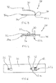
- a covering element 10 such as a door stick, for example, has an element of fastener 12 carried by a bridge 14 arranged on the inner face 16 of the rod 10.
- the bridge 14 has two vertical walls 14a connected by a horizontal wall 14b.
- the fastening element 12 is a drain having a base 18 having an enlarged portion tapering longitudinally surmounted by a flat surface 20 overflowing around base 18,
- the inner face 16 of the rod 10 also comprises a means of holding 22 composed of an inclined elastic blade 24 of which one free end is provided with a lug 26.
- a staple 28 is provided with a elastic upper arm 30 whose end comprises a finger 32 and a lower arm 34 shifted transversely relative to the arm higher 30.
- the clip 28 also comprises a transverse guiding means 35 carried by the Leader arm 34 and two transverse stops 37a and 37b.
- the guide means 35 extends inwardly of the staple 28.
- the stop 37a is carried by the end of the lower arm 34 and extends to the outside of the staple 28.
- the abutment 37b is at the junction of upper and lower arms 30 and 34 and extends from each side of the arm 30.
- the clip 28 also has a gripping zone 36 at junction point of the arms 30 and 34.
- the clip can be inserted into inside the trigger guard 14,
- the operator slides longitudinally the clip 28 to the interior of the bridge 14 by pressing on the upper arm 30 and holding the staple by its gripping zone 36.
- the staple 28 is all first guided by the sliding of the lower arm 34 along a walls 14a of the bridge 14.
- the guide means 35 allows to refocus the staple 28 by guiding it along the second 14a wall, so that the finger 32 can be vis-à-vis the hole 38 in its final position.
- the upper arm 30 is then kept under tension by the wall horizontal 14b of the trigger guard 14 until the finger 32 penetrates automatically in a hole 38 formed in the wall 14b.
- the abutments 37a and 37b cooperate with the walls 14a of the bridge 14 and block the clip 28 so as to prevent its longitudinal displacement forwards or backwards.
- the finger 32 does not risk then more out of the hole 38 and the staple 28 remains well in square.
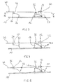
- the rod 10 is in position initial installation, against a support 40 such as a sheet, by example.
- a light 42 orientation overall longitudinal and keyhole-shaped, is arranged in the support 40. It has a wide part 42a and a narrow part 42b. It also has an edge 43 located at the opposite of the narrow zone 42b.
- the base 18 of the fastening element 12 penetrates in the wide area 42a of the light 42.
- the contact surface of the support 40 exerts pressure on the finger 32 of the upper arm 30 of the clip 28 and the lug 26 of the means of hold 22, which are then kept under tension.
- the rod 10 has been moved longitudinally with respect to the support 40 from its position initially to an intermediate position of placement.
- the element fastener 12 begins to move inside the light 42 so that the thinned portion of the base 18 enters the area narrower 42b of light 42.
- the finger 32 carried by the upper arm 30 of the clip 28 arrives in vis-à-vis the light 42 and enters it automatically, forming then a locking means preventing the return of the rod 10 towards its initial position.
- the holding means 22 is then still maintained under tension by the support 40.
- the rod 10 continued its longitudinal displacement to move from its intermediate position towards a final positon of setting up.
- the thinned portion of the base 18, held vertically by the surface plane 20, has completely penetrated inside the more narrow 42b of the longitudinal lumen, the locking finger 32 still cooperating with the wide part 42a of the 42 light. remains between the locking means and the edge 43 of the light a game enough to allow the rod to slide again very slightly, but not important enough to cause the release of the thinned portion of the base 18 from the narrow zone 42b of the light 42 and the detachment of the rod 10.
- the operator To dismount the covering element 10, the operator must exercise a pressing on the lug 26 of the holding means 22 while moving lightly the rod 10 in the way to release the ergot 26 of the orifice 44. Then it presses on the finger 36 of the clip 28 all by moving the rod longitudinally so as to clear the fixing means 12 of the light 42.
- the dressing element 10 however removable in case of need (repair or replacement of the trim element, simplified disassembly for recycling the vehicle at the end of life, ...), but requires the intervention of an operator.
- the dressing element can not detach itself without intervention of an operator, the invention thus has the advantage of propose a safer double anti-return system to limit the risks of bad assembly and falling of the dressing element.
Landscapes
- Engineering & Computer Science (AREA)
- General Engineering & Computer Science (AREA)
- Mechanical Engineering (AREA)
- Connection Of Plates (AREA)
- Insertion Pins And Rivets (AREA)
- Lighting Device Outwards From Vehicle And Optical Signal (AREA)
- Vehicle Interior And Exterior Ornaments, Soundproofing, And Insulation (AREA)
Applications Claiming Priority (2)
| Application Number | Priority Date | Filing Date | Title |
|---|---|---|---|
| FR0311428 | 2003-09-30 | ||
| FR0311428A FR2860273B1 (fr) | 2003-09-30 | 2003-09-30 | Agencement pour le montage d'un element d'habillage |
Publications (2)
| Publication Number | Publication Date |
|---|---|
| EP1520999A2 true EP1520999A2 (de) | 2005-04-06 |
| EP1520999A3 EP1520999A3 (de) | 2006-05-03 |
Family
ID=34307268
Family Applications (1)
| Application Number | Title | Priority Date | Filing Date |
|---|---|---|---|
| EP04300643A Withdrawn EP1520999A3 (de) | 2003-09-30 | 2004-09-30 | Anordnung für die Montage eines Verkleidungsteil |
Country Status (2)
| Country | Link |
|---|---|
| EP (1) | EP1520999A3 (de) |
| FR (1) | FR2860273B1 (de) |
Cited By (1)
| Publication number | Priority date | Publication date | Assignee | Title |
|---|---|---|---|---|
| DE102014100148B4 (de) | 2013-01-14 | 2023-05-04 | GM Global Technology Operations LLC (n. d. Gesetzen des Staates Delaware) | Verkleidungsanbringungsanordnung |
Family Cites Families (4)
| Publication number | Priority date | Publication date | Assignee | Title |
|---|---|---|---|---|
| US2958109A (en) * | 1958-03-13 | 1960-11-01 | Prestole Corp | Molding fastener |
| FR2787074B1 (fr) * | 1998-12-09 | 2001-03-16 | Aries Ind Structure | Ceinture de caisse de vehicules automobiles |
| FR2851970B1 (fr) * | 2003-03-05 | 2006-03-17 | Rehau Sa | Dispositif de verrouillage longitudinal de securite pour piece rapportee sur la tole de carrosserie d'un vehicule routier |
| FR2853602B1 (fr) * | 2003-04-09 | 2005-05-27 | Rehau Sa | Dispositif de securite par blocage avec effet anti-recul, pour piece rapportee sur la tole de carrosserie d'un vehicule routier |
-
2003
- 2003-09-30 FR FR0311428A patent/FR2860273B1/fr not_active Expired - Fee Related
-
2004
- 2004-09-30 EP EP04300643A patent/EP1520999A3/de not_active Withdrawn
Cited By (1)
| Publication number | Priority date | Publication date | Assignee | Title |
|---|---|---|---|---|
| DE102014100148B4 (de) | 2013-01-14 | 2023-05-04 | GM Global Technology Operations LLC (n. d. Gesetzen des Staates Delaware) | Verkleidungsanbringungsanordnung |
Also Published As
| Publication number | Publication date |
|---|---|
| FR2860273A1 (fr) | 2005-04-01 |
| EP1520999A3 (de) | 2006-05-03 |
| FR2860273B1 (fr) | 2005-11-18 |
Similar Documents
| Publication | Publication Date | Title |
|---|---|---|
| WO2015162365A1 (fr) | Dispositif de fixation par cramponnage | |
| EP1251284A1 (de) | Gruppe von zwei Karosserieteilen die Kante an Kante zusammenzufügen sind und Karosserieteil aus einer solchen Bauteilgruppe | |
| FR2780927A1 (fr) | Dispositif de fixation des crosses d'un pare-chocs sur une aile de carrosserie de vehicule | |
| FR2979400A1 (fr) | Structure de fixation utilisant des pinces | |
| FR2857314A1 (fr) | Dispositif de fixation des parties laterales en forme de crosse du pare-chocs avant d'un vehicule automobile aux ailes de ce dernier | |
| EP1520999A2 (de) | Anordnung für die Montage eines Verkleidungsteil | |
| FR2952144A1 (fr) | Joint de finition adapte pour etre fixe entre deux vitrages et vehicule automobile comportant deux vitrages separes par un interstice comportant un tel joint de finition. | |
| EP2833004A1 (de) | Träger für Klammer | |
| FR2900897A1 (fr) | Fixation glissante d'une aile a une caisse en blanc de vehicule automobile et procede de fixation utilisant une telle fixation | |
| EP4012122B1 (de) | Regenwassersammler zur montage an einem dachrinnenfallrohr, der ein abnehmbares schöpfgefäss umfasst | |
| EP1320163B1 (de) | Immobilisierungszubehör für ein elektrisches Installationsgerät mit Direktschnappverbindung in einem Kabelrinnesockel | |
| EP1252045B1 (de) | Vorrichtung zur befestigung der seitenschenkel einer stossstange | |
| EP1728687B1 (de) | Anordnung zur Montage einer Zierleiste an einem Kraftfahrzeug Karosserieteil | |
| EP0169747A1 (de) | Stossdämpfer für Fahrzeug | |
| EP0730997B1 (de) | Dekoratives Teil aus Kunststoff | |
| FR2486993A1 (fr) | Pince de fixation de baguette | |
| FR2779335A1 (fr) | Fixation pour tringle de vitrage | |
| EP1258389B1 (de) | Verschlussvorrichtung für eine Öffnung zum Befestigen eines Gegenstandes, wie z.B. einen Kraftfahrzeugsitz | |
| EP1284218A1 (de) | Halterungsvorrichtung und System für einen Kraftfahrzeugdachkoffer | |
| EP0685655B1 (de) | Elastische Befestigungsklammer | |
| EP1877284B1 (de) | Vorderstangenanordnung für ein kraftfahrzeug | |
| WO2019239031A1 (fr) | Bord de panneau conforme pour la réception d'une pince a écrou | |
| FR2972745A1 (fr) | Dispositif de support et de fixation d'un accessoire de construction, tel qu'un crochet de gouttiere, a une couverture de toit | |
| FR2934557A1 (fr) | Systeme d'indexage d'un organe eclairant sur un vehicule automobile. | |
| FR3154367A1 (fr) | Presseur de pare-chocs de véhicule automobile comprenant une extension latérale de renforcement |
Legal Events
| Date | Code | Title | Description |
|---|---|---|---|
| PUAI | Public reference made under article 153(3) epc to a published international application that has entered the european phase |
Free format text: ORIGINAL CODE: 0009012 |
|
| AK | Designated contracting states |
Kind code of ref document: A2 Designated state(s): AT BE BG CH CY CZ DE DK EE ES FI FR GB GR HU IE IT LI LU MC NL PL PT RO SE SI SK TR |
|
| AX | Request for extension of the european patent |
Extension state: AL HR LT LV MK |
|
| PUAL | Search report despatched |
Free format text: ORIGINAL CODE: 0009013 |
|
| AK | Designated contracting states |
Kind code of ref document: A3 Designated state(s): AT BE BG CH CY CZ DE DK EE ES FI FR GB GR HU IE IT LI LU MC NL PL PT RO SE SI SK TR |
|
| AX | Request for extension of the european patent |
Extension state: AL HR LT LV MK |
|
| 17P | Request for examination filed |
Effective date: 20061103 |
|
| AKX | Designation fees paid |
Designated state(s): AT BE BG CH CY CZ DE DK EE ES FI FR GB GR HU IE IT LI LU MC NL PL PT RO SE SI SK TR |
|
| 17Q | First examination report despatched |
Effective date: 20070125 |
|
| STAA | Information on the status of an ep patent application or granted ep patent |
Free format text: STATUS: THE APPLICATION IS DEEMED TO BE WITHDRAWN |
|
| 18D | Application deemed to be withdrawn |
Effective date: 20070606 |