EP1520980A2 - Kraftstoffeinspritzventil - Google Patents
Kraftstoffeinspritzventil Download PDFInfo
- Publication number
- EP1520980A2 EP1520980A2 EP04023397A EP04023397A EP1520980A2 EP 1520980 A2 EP1520980 A2 EP 1520980A2 EP 04023397 A EP04023397 A EP 04023397A EP 04023397 A EP04023397 A EP 04023397A EP 1520980 A2 EP1520980 A2 EP 1520980A2
- Authority
- EP
- European Patent Office
- Prior art keywords
- magneto
- plunger
- injection valve
- striction
- fuel injection
- Prior art date
- Legal status (The legal status is an assumption and is not a legal conclusion. Google has not performed a legal analysis and makes no representation as to the accuracy of the status listed.)
- Granted
Links
Images


Classifications
-
- F—MECHANICAL ENGINEERING; LIGHTING; HEATING; WEAPONS; BLASTING
- F02—COMBUSTION ENGINES; HOT-GAS OR COMBUSTION-PRODUCT ENGINE PLANTS
- F02M—SUPPLYING COMBUSTION ENGINES IN GENERAL WITH COMBUSTIBLE MIXTURES OR CONSTITUENTS THEREOF
- F02M61/00—Fuel-injectors not provided for in groups F02M39/00 - F02M57/00 or F02M67/00
- F02M61/16—Details not provided for in, or of interest apart from, the apparatus of groups F02M61/02 - F02M61/14
- F02M61/168—Assembling; Disassembling; Manufacturing; Adjusting
-
- F—MECHANICAL ENGINEERING; LIGHTING; HEATING; WEAPONS; BLASTING
- F02—COMBUSTION ENGINES; HOT-GAS OR COMBUSTION-PRODUCT ENGINE PLANTS
- F02M—SUPPLYING COMBUSTION ENGINES IN GENERAL WITH COMBUSTIBLE MIXTURES OR CONSTITUENTS THEREOF
- F02M51/00—Fuel-injection apparatus characterised by being operated electrically
- F02M51/06—Injectors peculiar thereto with means directly operating the valve needle
- F02M51/0603—Injectors peculiar thereto with means directly operating the valve needle using piezoelectric or magnetostrictive operating means
- F02M51/0607—Injectors peculiar thereto with means directly operating the valve needle using piezoelectric or magnetostrictive operating means the actuator being hollow, e.g. with needle passing through the hollow space
-
- F—MECHANICAL ENGINEERING; LIGHTING; HEATING; WEAPONS; BLASTING
- F02—COMBUSTION ENGINES; HOT-GAS OR COMBUSTION-PRODUCT ENGINE PLANTS
- F02M—SUPPLYING COMBUSTION ENGINES IN GENERAL WITH COMBUSTIBLE MIXTURES OR CONSTITUENTS THEREOF
- F02M61/00—Fuel-injectors not provided for in groups F02M39/00 - F02M57/00 or F02M67/00
- F02M61/16—Details not provided for in, or of interest apart from, the apparatus of groups F02M61/02 - F02M61/14
- F02M61/167—Means for compensating clearance or thermal expansion
-
- F—MECHANICAL ENGINEERING; LIGHTING; HEATING; WEAPONS; BLASTING
- F02—COMBUSTION ENGINES; HOT-GAS OR COMBUSTION-PRODUCT ENGINE PLANTS
- F02M—SUPPLYING COMBUSTION ENGINES IN GENERAL WITH COMBUSTIBLE MIXTURES OR CONSTITUENTS THEREOF
- F02M61/00—Fuel-injectors not provided for in groups F02M39/00 - F02M57/00 or F02M67/00
- F02M61/16—Details not provided for in, or of interest apart from, the apparatus of groups F02M61/02 - F02M61/14
- F02M61/161—Means for adjusting injection-valve lift
Definitions
- the present invention relates to a fuel injector of an inward opening type using a magneto-striction element suitable for an internal combustion engine.
- An internal combustion engine for a car requires an advanced mixed gas forming art of injected fuel and air and a highly precise fuel injection art. To execute precise control for the fuel injection rate, a high degree of response is required for a fuel injection valve.
- a one using a magneto-striction element has been developed.
- the outward opening type and inward opening type are known.
- the outward opening type fuel injection valve has a structure that the valve body (plunger) moves toward the combustion chamber.
- the inward opening type fuel injection valve for example, as described in Japanese Laid-open Patent Publication 9-310654, has a structure that the plunger is pulled up and fuel is injected, so that a problem of accumulation of deposits is hardly imposed.
- the magneto-striction element is a material that the dimensional accuracy at the time of processing is hardly obtained, so that a problem arises that dimensional variations are large.
- Japanese laid-open Patent Publication 9-310654 a structure is used that a gap is provided between the slider and the plunger rod and the gap absorbs variations in the processing accuracy.
- one end of the element is fixed to the main unit case via the element holder, so that variations in the processing dimensions of the element adversely affect straight the dimensions of the gap and a problem arises that only by the element and element holder, dimensional variations cannot be adjusted.
- the thermal expansion coefficient of the magneto-striction element is comparatively large, for example, about 12 ppm/°C.
- the atmospheric temperature is changed extremely large such as from -30°C to 120°C, so that for example, when the atmospheric temperature is changed by 100°C, the change in the elongation of the element reaches about 120 ⁇ m.
- This elongation change is more than the request stroke (generally in the order of several tens ⁇ m) of the injection valve, so that not only precise control of the fuel injection amount cannot be executed due to the thermal expansion of the element but also according to circumstances, a problem arises that the function of the injection valve is lost.
- An object of the present invention is to provide a fuel injection valve that there are very few product variations, and the problem due to the thermal expansion is solved, and the measurement accuracy and reliability are high.
- the present invention provides a fuel injection valve that there are very few product variations, and the problem due to the thermal expansion is solved, and the measurement accuracy and reliability are high.
- Fig. 1 is a cross sectional view showing the whole constitution of the fuel injection valve of an embodiment of the present invention.
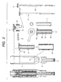
- Fig. 2 is an assembly drawing of the fuel injection valve of an embodiment of the present invention.
- the same numerals indicate the same parts.
- a nozzle sheet 3 is fit into the front end of a nozzle body 2.
- a nozzle is formed and the shape thereof is the same as the conventional one.
- the shape of the front end of a plunger rod 12 in contact with the nozzle sheet 3 is the same as the conventional one.
- the plunger rod 12 is an integral comparatively long rod interconnecting from the nozzle sheet to the upper part of the element drive portion.
- a flange 11 is installed integrally with the rod 12 and constitutes a plunger assembly 18.
- an elastic body such as a plunger sheet spring 9 held by a stopper 4 is arranged.
- the spring 9, via the plunger rod 12, can always act an appropriate load to the nozzle sheet 3 completely independently of the element portion.
- the load of the sheet portion is sheet force necessary to prevent the nozzle sheet portion from leakage of fuel.
- a magneto-striction element 7 is cylindrical.
- the cylindrical magneto-striction element 7 is inserted into an element holder assembly 6 installed in the cylindrical inner groove.
- the element holder assembly 6 is composed of a holder outer cylinder 14, a holder inner cylinder 15, a holder flange 13, and a holder bottom plate 16, which are integrated with each other.
- the holder outer cylinder 14 and the holder inner cylinder 15 are arranged concentrically with each other and in the inner groove formed between the two, the magneto-striction element 7 is inserted.
- the holder flange 13 projected in the horizontal direction on the upper part of the element holder assembly 6 is fit, positioned, and fixed to the main unit case 1 of the injection valve.
- the position X1 of the fixed holder flange 13 is a fixed end.
- the holder inner cylinder 15 is not always installed, and it is a protection tube for protecting the magneto-striction element 7 which is made of a comparatively fragile material, and it can play a roll of preventing the magneto-striction element 7 from making direct contact with the plunger rod 12 and subject to wear. Further, the holder inner cylinder 15 may be used as a guide member when the plunger rod 1 2 slides vertically.
- the element holder assembly 6 and the main unit case 1 are fixed only at the portion of the holder flange 13 and the lower end of the element holder assembly 6 is formed as a free end which is provided with a gap and can be freely deformed vertically.
- the holder outer cylinder 14 and the holder inner cylinder 15 are made of a non-magnetic material and the bottom plate 16 of the element holder is made of a magnetic material.
- the holder outer cylinder 14 is made of a material having the same thermal expansion coefficient as the thermal expansion coefficient of the magneto-striction element 7.
- the element receiving member 5 and the bottom plate 16 use SUS420J2 which is a magnetic material and the holder flange 13, the holder outer cylinder 14, and the holder inner cylinder 15 use K-M35FL which is a non-magnetic material.
- the coefficient of linear expansion of the magneto-striction element 7 is 12 ppm
- the coefficient of linear expansion thereof is also 12 ppm and can be made equal to the coefficient of linear expansion of the magneto-striction element 7.
- an injection valve having the elongation of the magneto-striction element 7 and the tensile strength withstandable for the extension force generated by the magneto-striction element and the pre-load can be obtained.
- sectional area of the outer cylinder 14 is a sectional area withstandable for the elongation force generated by the magneto-striction element 7.
- the element receiving member 5 On the upper end face of the magneto-striction element 7 inserted into the element holder assembly 6, the element receiving member 5 is arranged. On the top of the element receiving member 5, an elastic body such as an element pre-load spring 10 guided by the guide 18 is arranged. By the elastic body such as the spring 10, to the magneto-striction element 7, a fixed pre-load is given always via the element receiving member 5.
- an appropriate gap is provided in the vertical direction (the stroke direction).
- the gap length in consideration of processing variations (tolerance) of each component, is predetermined. Namely, from the final tolerance of each component, the gap length may be obtained as more than 0.
- the gap length provided between the upper part of the element receiving member 5 and the plunger flange 11 is assumed as G1.
- the origin O for example, is set to the position where the front end of the rod 12 shown in Fig. 1 makes contact with the nozzle sheet 3.
- the length from the origin O to the bottom of the plunger flange 11 is assumed as L1.
- the length L1 is assumed to have a tolerance of ⁇ L1.
- the gap length G1 can be expressed by the following formula (1).
- G1 L1 - (L2 - L3 + L4 + L5)
- G1 ((L1 + ⁇ L1) - (L2 + ⁇ L2) - (L3 + ⁇ L3) + (L4 + ⁇ L4) + (L5 + ⁇ L5)) >
- the gap G1 provided between the magneto-striction element 7 and the plunger rod 12, that is, the gap length G1 provided between the upper part of the element receiving member 5 and the plunger flange 11 is set to the minimum clearance or more obtained from the dimensional tolerance added at the time of assembly of each component of the injection valve.
- a gap (stroke amount) is provided and the gap is an effective stroke of the plunger.
- the nozzle starts to open the valve.
- a constitution that by the stopper 4 fixed to the main unit case 1, the maximum lift is controlled is used.
- a fine adjustment shim may be installed in the gap portion and the stoke portion.
- a stroke adjustment mechanism of the plunger 13 a constitution similar to the conventional one may be used.
- a coil incorporated in a coil bobbin assembly 8 is arranged.
- a fuel path is arranged by providing a hole or a groove in a part of the components.
- a clearance may be formed between the rod 12 and the element holder assembly 6 so as to be used as a fuel path and the rod 12 may be formed in a cylindrical shape so as to provide a fuel path at the central part.
- Fig. 3 is an illustration for the operation of the fuel injection valve of an embodiment of the present invention. Further, the same numerals as those shown in Figs. 1 and 2 indicate the same parts.
- Fig. 8(A) shows a state that no power is supplied to a coil 8A.
- the adjustment gap G1 is formed between the element receiving member 5 and the plunger flange 11, the adjustment gap G1 is formed. Further, at this time, between the plunger flange 11 and the stopper 4, the gap (stroke length) L1 for the plunger lift is formed.
- the gap L1 between the plunger rod 12 and the stopper 4 is an effective lift of the injection valve.
- the gap G1 between the element receiving member 5 and the flange 11 of the plunger rod 12 is a final fine adjustment portion to adjust in correspondence with fine dimensional variations in each component of the injection valve within the processing tolerance and slight changes in the use environmental conditions, thus the dimensional accuracy of the injection valve can be improved more. Further, here, comparatively large dimensional variations of the element itself are absorbed by selective fitting into the element holder.
- a holder outer cylinder 14 longer than the specified dimension by about 20 ⁇ m is selected and the two are assembled as parts of the same fuel injection valve.
- This embodiment uses such a two-step dimension adjustment mechanism.
- a solid line Y1 indicates a lift amount of the element receiving member 5 and a dashed line Y2 indicates a lift amount of the plunger 12.
- the sum of the length of the gap G1 and the plunger lift L1 as shown in the drawing is the overall elongation of the magneto-striction element 7.
- the length of the gap G1 is, for example, 10 to 20 ⁇ m and the plunger lift L1 is, for example, 40 ⁇ m.
- the element holder assembly 6 having the same coefficient of linear expansion as that of the element perfectly follows (in proportion) the extension of the magneto-striction element 7 and expands and contracts at the free end, so that at the position X1 of the fixed end of the element holder assembly 6 and the main unit case 1, the assembly 6 is apparently equivalent to a state free of thermal expansion.
- the dimension between the position X1 of the fixed end of the element holder assembly 6 and the position of the upper end face of the magneto-striction element 7 is always kept fixed relatively, so that highly accurate dimension setting is enabled and manufacture variations in products can be suppressed. Furthermore, super accurate control of the fuel injection rate can be executed.
- dimensional changing due to the thermal expansion is a phenomenon similarly presented not only in the magneto-striction element but also in the plunger rod and main unit case.
- the plunger rod and main unit case are made of metallic materials having the same thermal expansion coefficient, so that the dimensional changing due to the thermal expansion can be automatically cancelled.
- a two-step independent cancel mechanism is used that by appropriate selection of an element holder material, the difference in thermal expansion between the element and the element holder portion is cancelled and furthermore the difference in thermal expansion between the main unit case and the plunger rod is cancelled. Further, if the thermal expansion coefficient of the element does not coincide perfectly with that of the element holder, for the components of the plunger rod, main unit case, and nozzle body affecting the gap length, materials having various different and appropriate thermal expansion coefficients are combined, thus the gap length to be set finally can be kept at a certain fixed value.
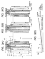
- Fig. 4 is a cross sectional view showing the whole constitution of the fuel injection valve of another embodiment of the present invention.
- Fig. 4(A) is an entire view thereof and
- Fig. 4(B) is a partially enlarged view of Fig. 4(A).
- the same numerals as those shown in Figs. 1 and 2 indicate the same parts.
- the basic constitution of this embodiment is the same as that shown in Figs. 1 to 3.
- elastic bodies 19A and 19B such as O-rings or rubber are mounted on the inner peripheral side and outer peripheral side so as to surround the magneto-striction element.
- the gap portion the gap length is changed by the expansion and contraction of the element, so that to fix the seal member, a fixed groove such as an O-ring groove may be formed on the holder side or the element receiving member side. Further, the top or bottom of the seal member may be adhered.
- the magneto-striction element 7 is made of a comparatively fragile material, and when it is repeatedly expanded and contracted at a large load, the corners of the element end face are easily chipped, and chipped small fragments are dissolved into fuel, and the injection valve nozzle may be clogged or the movable part may be worn away. Therefore, the flexible elastic bodies 19A and 19B are respectively mounted on the outer peripheral side and inner peripheral side of the element, thus even if a part of the element is chipped, fragments thereof can be prevented from flowing into fuel.
- the injection valve is filled with high-pressure fuel.
- the elastic bodies 19A and 19B are used to prevent small chipped fragments of the element from flowing to the outside and do not aim at sealing high-pressure fuel, so that minute fuel leakage from the gap does not matter.
- the mounting position of the seal member 19B installed on the outer peripheral side of the element is set on the outer peripheral side (large diameter) of the element receiving member 5 inasmuch as is possible, thus the falling and bending of the columnar element receiving member 5 with a comparatively large diameter can be buffered. Further, the outer seal member 19B is widened, thus the falling and bending of the element receiving member can be further eliminated.
- striction element 7 uses a cylindrical element, though for example, two semi-cylindrical elements may be combined and arranged in a cylindrical shape. Further, thin columnar magneto-striction elements may be evenly arranged in a shape of torus around the plunger rod 12. Namely, as a magneto-striction element, an annular element in which extension force evenly acts on the flange 11 of the plunger rod 12 may be used.
- the dimensions of the plunger portion and element portion requiring high accuracy can be set independently, and the portions are structured free of mutual interference, thus the reliability is high, and there are few manufacture variations, and high dimensional accuracy can be realized, so that highly precise fuel injection amount control can be executed.
- a constitution that a rapid response magneto-striction element directly drives the plunger is used, so that compared with the conventional solenoid type, the valve opening delay and closing delay are greatly shortened and very rapid response and highly precise fuel injection amount control can be executed.
Landscapes
- Engineering & Computer Science (AREA)
- Chemical & Material Sciences (AREA)
- Combustion & Propulsion (AREA)
- Mechanical Engineering (AREA)
- General Engineering & Computer Science (AREA)
- Manufacturing & Machinery (AREA)
- Analytical Chemistry (AREA)
- Fuel-Injection Apparatus (AREA)
Applications Claiming Priority (2)
| Application Number | Priority Date | Filing Date | Title |
|---|---|---|---|
| JP2003345261A JP4002229B2 (ja) | 2003-10-03 | 2003-10-03 | 燃料噴射弁 |
| JP2003345261 | 2003-10-03 |
Publications (3)
| Publication Number | Publication Date |
|---|---|
| EP1520980A2 true EP1520980A2 (de) | 2005-04-06 |
| EP1520980A3 EP1520980A3 (de) | 2006-11-22 |
| EP1520980B1 EP1520980B1 (de) | 2010-07-21 |
Family
ID=34309150
Family Applications (1)
| Application Number | Title | Priority Date | Filing Date |
|---|---|---|---|
| EP04023397A Expired - Lifetime EP1520980B1 (de) | 2003-10-03 | 2004-10-01 | Kraftstoffeinspritzventil |
Country Status (4)
| Country | Link |
|---|---|
| US (1) | US20050098663A1 (de) |
| EP (1) | EP1520980B1 (de) |
| JP (1) | JP4002229B2 (de) |
| DE (1) | DE602004028202D1 (de) |
Cited By (2)
| Publication number | Priority date | Publication date | Assignee | Title |
|---|---|---|---|---|
| EP1741921A1 (de) * | 2005-07-04 | 2007-01-10 | Hitachi, Ltd. | Brennstoffeinspritzventil |
| FR3039221A1 (fr) * | 2015-07-23 | 2017-01-27 | Continental Automotive France | Procede de compensation de la derive du jeu fonctionnel d'un injecteur d'un moteur a combustion interne d'un vehicule |
Families Citing this family (25)
| Publication number | Priority date | Publication date | Assignee | Title |
|---|---|---|---|---|
| JP2007081838A (ja) * | 2005-09-14 | 2007-03-29 | Opt Kk | 超磁歪アクチュエータを用いた発音具 |
| US7311084B2 (en) * | 2006-01-27 | 2007-12-25 | Angus Barry Begg | Fuel injection system |
| WO2007122841A1 (ja) * | 2006-03-29 | 2007-11-01 | Keihin Corporation | 燃料噴射弁 |
| US8074625B2 (en) * | 2008-01-07 | 2011-12-13 | Mcalister Technologies, Llc | Fuel injector actuator assemblies and associated methods of use and manufacture |
| US8365700B2 (en) | 2008-01-07 | 2013-02-05 | Mcalister Technologies, Llc | Shaping a fuel charge in a combustion chamber with multiple drivers and/or ionization control |
| US8225768B2 (en) | 2008-01-07 | 2012-07-24 | Mcalister Technologies, Llc | Integrated fuel injector igniters suitable for large engine applications and associated methods of use and manufacture |
| US8561598B2 (en) | 2008-01-07 | 2013-10-22 | Mcalister Technologies, Llc | Method and system of thermochemical regeneration to provide oxygenated fuel, for example, with fuel-cooled fuel injectors |
| US8387599B2 (en) | 2008-01-07 | 2013-03-05 | Mcalister Technologies, Llc | Methods and systems for reducing the formation of oxides of nitrogen during combustion in engines |
| US7628137B1 (en) | 2008-01-07 | 2009-12-08 | Mcalister Roy E | Multifuel storage, metering and ignition system |
| US8413634B2 (en) | 2008-01-07 | 2013-04-09 | Mcalister Technologies, Llc | Integrated fuel injector igniters with conductive cable assemblies |
| US8635985B2 (en) | 2008-01-07 | 2014-01-28 | Mcalister Technologies, Llc | Integrated fuel injectors and igniters and associated methods of use and manufacture |
| CN102713244A (zh) | 2009-08-27 | 2012-10-03 | 麦卡利斯特技术有限责任公司 | 在具有多个驱动器和/或电离控制的燃烧室中成形供应燃料 |
| EP2470485A4 (de) | 2009-08-27 | 2012-12-26 | Mcalister Technologies Llc | Keramikisolator sowie herstellungsverfahren und verwendungsverfahren dafür |
| KR20120086375A (ko) | 2009-12-07 | 2012-08-02 | 맥알리스터 테크놀로지즈 엘엘씨 | 연료 인젝터 및 점화기를 위한 적응 제어 시스템 |
| US20110297753A1 (en) | 2010-12-06 | 2011-12-08 | Mcalister Roy E | Integrated fuel injector igniters configured to inject multiple fuels and/or coolants and associated methods of use and manufacture |
| CN102844540A (zh) | 2010-02-13 | 2012-12-26 | 麦卡利斯特技术有限责任公司 | 用于自适应地冷却发动机中的燃烧室的方法和系统 |
| US8205805B2 (en) | 2010-02-13 | 2012-06-26 | Mcalister Technologies, Llc | Fuel injector assemblies having acoustical force modifiers and associated methods of use and manufacture |
| US8528519B2 (en) | 2010-10-27 | 2013-09-10 | Mcalister Technologies, Llc | Integrated fuel injector igniters suitable for large engine applications and associated methods of use and manufacture |
| US8091528B2 (en) | 2010-12-06 | 2012-01-10 | Mcalister Technologies, Llc | Integrated fuel injector igniters having force generating assemblies for injecting and igniting fuel and associated methods of use and manufacture |
| US8820275B2 (en) | 2011-02-14 | 2014-09-02 | Mcalister Technologies, Llc | Torque multiplier engines |
| US8919377B2 (en) | 2011-08-12 | 2014-12-30 | Mcalister Technologies, Llc | Acoustically actuated flow valve assembly including a plurality of reed valves |
| CN103890343B (zh) | 2011-08-12 | 2015-07-15 | 麦卡利斯特技术有限责任公司 | 用于改进的发动机冷却及能量产生的系统和方法 |
| US9309846B2 (en) | 2012-11-12 | 2016-04-12 | Mcalister Technologies, Llc | Motion modifiers for fuel injection systems |
| US9091238B2 (en) | 2012-11-12 | 2015-07-28 | Advanced Green Technologies, Llc | Systems and methods for providing motion amplification and compensation by fluid displacement |
| US9903326B2 (en) * | 2014-05-15 | 2018-02-27 | Cummins Inc. | Fuel injector having a magnetostrictive actuator device |
Family Cites Families (8)
| Publication number | Priority date | Publication date | Assignee | Title |
|---|---|---|---|---|
| US2721100A (en) * | 1951-11-13 | 1955-10-18 | Jr Albert G Bodine | High frequency injector valve |
| US5361053A (en) * | 1993-10-07 | 1994-11-01 | Unisia Jecs Corporation | Super magnetostriction type actuator |
| JPH09310654A (ja) * | 1996-05-20 | 1997-12-02 | Hitachi Ltd | 燃料噴射弁 |
| DE19901711A1 (de) * | 1999-01-18 | 2000-07-20 | Bosch Gmbh Robert | Brennstoffeinspritzventil und Verfahren zum Betreiben eines Brennstoffeinspritzventils |
| DE19947779A1 (de) * | 1999-10-02 | 2001-04-12 | Bosch Gmbh Robert | Brennstoffeinspritzventil |
| US6584958B2 (en) * | 1999-10-15 | 2003-07-01 | Westport Research Inc. | Directly actuated injection valve with a ferromagnetic needle |
| US6279842B1 (en) * | 2000-02-29 | 2001-08-28 | Rodi Power Systems, Inc. | Magnetostrictively actuated fuel injector |
| DE10153630A1 (de) * | 2001-10-31 | 2003-07-10 | Bosch Gmbh Robert | Brennstoffeinspritzventil |
-
2003
- 2003-10-03 JP JP2003345261A patent/JP4002229B2/ja not_active Expired - Fee Related
-
2004
- 2004-10-01 DE DE602004028202T patent/DE602004028202D1/de not_active Expired - Lifetime
- 2004-10-01 EP EP04023397A patent/EP1520980B1/de not_active Expired - Lifetime
- 2004-10-01 US US10/954,366 patent/US20050098663A1/en not_active Abandoned
Cited By (2)
| Publication number | Priority date | Publication date | Assignee | Title |
|---|---|---|---|---|
| EP1741921A1 (de) * | 2005-07-04 | 2007-01-10 | Hitachi, Ltd. | Brennstoffeinspritzventil |
| FR3039221A1 (fr) * | 2015-07-23 | 2017-01-27 | Continental Automotive France | Procede de compensation de la derive du jeu fonctionnel d'un injecteur d'un moteur a combustion interne d'un vehicule |
Also Published As
| Publication number | Publication date |
|---|---|
| US20050098663A1 (en) | 2005-05-12 |
| JP4002229B2 (ja) | 2007-10-31 |
| JP2005113699A (ja) | 2005-04-28 |
| EP1520980B1 (de) | 2010-07-21 |
| DE602004028202D1 (de) | 2010-09-02 |
| EP1520980A3 (de) | 2006-11-22 |
Similar Documents
| Publication | Publication Date | Title |
|---|---|---|
| EP1520980B1 (de) | Kraftstoffeinspritzventil | |
| EP1907687B1 (de) | Kraftstoffeinspritzventil mit piezoelektrischer stellgliedvorbelastung | |
| US6837221B2 (en) | Fuel injector with feedback control | |
| US7048209B2 (en) | Magneto-hydraulic compensator for a fuel injector | |
| JP4247506B2 (ja) | 内燃機関用燃料噴射装置に用いる調整可能な絞り弁 | |
| US6474572B1 (en) | Fuel-injection valve | |
| EP1707797B1 (de) | Verstellbares Dosierservoventil eines Einspritzventils | |
| US20020179062A1 (en) | Hydraulic compensator for a piezoelectrical fuel injector | |
| US9086041B2 (en) | Fuel injector having a piezoelectric actuator and a sensor assembly | |
| US5626165A (en) | Valve for re-circulating exhaust gas | |
| GB2343936A (en) | Reduced impact solenoid operated valve | |
| EP1167748B1 (de) | Selbstkompensierender piezoelektrischer Aktuator für ein Steuerventil | |
| US6776390B1 (en) | Valve for controlling fluids | |
| US8752807B2 (en) | Seat block and valve device | |
| US7032833B2 (en) | Fuel injection valve | |
| EP1284358B1 (de) | Verbrennungsmotorskraftstoffeinspritzventil und Verfahren zu dessen Herstellung | |
| US7307371B2 (en) | Actuator with amplified stroke length | |
| CN100359156C (zh) | 燃油喷射器 | |
| US20040159811A1 (en) | Solenoid valve | |
| US6892956B2 (en) | Fuel injection valve | |
| ITTO20001230A1 (it) | Iniettore di combustibile per un motore a combustione interna. | |
| US20200072173A1 (en) | Injector | |
| US20070007363A1 (en) | Fuel injection valve | |
| KR20020025976A (ko) | 유체 제어용 밸브 | |
| WO2018066327A1 (ja) | 燃料噴射弁 |
Legal Events
| Date | Code | Title | Description |
|---|---|---|---|
| PUAI | Public reference made under article 153(3) epc to a published international application that has entered the european phase |
Free format text: ORIGINAL CODE: 0009012 |
|
| AK | Designated contracting states |
Kind code of ref document: A2 Designated state(s): AT BE BG CH CY CZ DE DK EE ES FI FR GB GR HU IE IT LI LU MC NL PL PT RO SE SI SK TR |
|
| AX | Request for extension of the european patent |
Extension state: AL HR LT LV MK |
|
| PUAL | Search report despatched |
Free format text: ORIGINAL CODE: 0009013 |
|
| AK | Designated contracting states |
Kind code of ref document: A3 Designated state(s): AT BE BG CH CY CZ DE DK EE ES FI FR GB GR HU IE IT LI LU MC NL PL PT RO SE SI SK TR |
|
| AX | Request for extension of the european patent |
Extension state: AL HR LT LV MK |
|
| 17P | Request for examination filed |
Effective date: 20070522 |
|
| AKX | Designation fees paid |
Designated state(s): DE FR IT |
|
| 17Q | First examination report despatched |
Effective date: 20080910 |
|
| GRAP | Despatch of communication of intention to grant a patent |
Free format text: ORIGINAL CODE: EPIDOSNIGR1 |
|
| GRAS | Grant fee paid |
Free format text: ORIGINAL CODE: EPIDOSNIGR3 |
|
| GRAA | (expected) grant |
Free format text: ORIGINAL CODE: 0009210 |
|
| AK | Designated contracting states |
Kind code of ref document: B1 Designated state(s): DE FR IT |
|
| REF | Corresponds to: |
Ref document number: 602004028202 Country of ref document: DE Date of ref document: 20100902 Kind code of ref document: P |
|
| PLBE | No opposition filed within time limit |
Free format text: ORIGINAL CODE: 0009261 |
|
| STAA | Information on the status of an ep patent application or granted ep patent |
Free format text: STATUS: NO OPPOSITION FILED WITHIN TIME LIMIT |
|
| PG25 | Lapsed in a contracting state [announced via postgrant information from national office to epo] |
Ref country code: IT Free format text: LAPSE BECAUSE OF FAILURE TO SUBMIT A TRANSLATION OF THE DESCRIPTION OR TO PAY THE FEE WITHIN THE PRESCRIBED TIME-LIMIT Effective date: 20100721 |
|
| 26N | No opposition filed |
Effective date: 20110426 |
|
| PG25 | Lapsed in a contracting state [announced via postgrant information from national office to epo] |
Ref country code: FR Free format text: LAPSE BECAUSE OF NON-PAYMENT OF DUE FEES Effective date: 20101102 |
|
| REG | Reference to a national code |
Ref country code: FR Ref legal event code: ST Effective date: 20110630 |
|
| REG | Reference to a national code |
Ref country code: DE Ref legal event code: R097 Ref document number: 602004028202 Country of ref document: DE Effective date: 20110426 |
|
| PGFP | Annual fee paid to national office [announced via postgrant information from national office to epo] |
Ref country code: DE Payment date: 20140923 Year of fee payment: 11 |
|
| REG | Reference to a national code |
Ref country code: DE Ref legal event code: R119 Ref document number: 602004028202 Country of ref document: DE |
|
| PG25 | Lapsed in a contracting state [announced via postgrant information from national office to epo] |
Ref country code: DE Free format text: LAPSE BECAUSE OF NON-PAYMENT OF DUE FEES Effective date: 20160503 |