EP1520976A2 - Système d'admission comprenant un accumulateur de pression - Google Patents
Système d'admission comprenant un accumulateur de pression Download PDFInfo
- Publication number
- EP1520976A2 EP1520976A2 EP04103906A EP04103906A EP1520976A2 EP 1520976 A2 EP1520976 A2 EP 1520976A2 EP 04103906 A EP04103906 A EP 04103906A EP 04103906 A EP04103906 A EP 04103906A EP 1520976 A2 EP1520976 A2 EP 1520976A2
- Authority
- EP
- European Patent Office
- Prior art keywords
- pressure accumulator
- intake system
- air collector
- intake
- housing part
- Prior art date
- Legal status (The legal status is an assumption and is not a legal conclusion. Google has not performed a legal analysis and makes no representation as to the accuracy of the status listed.)
- Withdrawn
Links
- 238000002485 combustion reaction Methods 0.000 claims description 13
- 238000000034 method Methods 0.000 claims description 6
- 238000003466 welding Methods 0.000 claims description 6
- 239000004033 plastic Substances 0.000 claims description 4
- 229920003023 plastic Polymers 0.000 claims description 4
- 238000000926 separation method Methods 0.000 claims description 2
- 230000006698 induction Effects 0.000 abstract 3
- 238000007789 sealing Methods 0.000 description 7
- 238000004519 manufacturing process Methods 0.000 description 5
- 238000003860 storage Methods 0.000 description 2
- 229920010540 PA6 GF30 Polymers 0.000 description 1
- 239000004952 Polyamide Substances 0.000 description 1
- 239000000853 adhesive Substances 0.000 description 1
- 230000001070 adhesive effect Effects 0.000 description 1
- 239000000463 material Substances 0.000 description 1
- 239000002184 metal Substances 0.000 description 1
- 229910052751 metal Inorganic materials 0.000 description 1
- 150000002739 metals Chemical class 0.000 description 1
- 229920002647 polyamide Polymers 0.000 description 1
Images

Classifications
-
- F—MECHANICAL ENGINEERING; LIGHTING; HEATING; WEAPONS; BLASTING
- F02—COMBUSTION ENGINES; HOT-GAS OR COMBUSTION-PRODUCT ENGINE PLANTS
- F02M—SUPPLYING COMBUSTION ENGINES IN GENERAL WITH COMBUSTIBLE MIXTURES OR CONSTITUENTS THEREOF
- F02M35/00—Combustion-air cleaners, air intakes, intake silencers, or induction systems specially adapted for, or arranged on, internal-combustion engines
- F02M35/10—Air intakes; Induction systems
- F02M35/1034—Manufacturing and assembling intake systems
- F02M35/10354—Joining multiple sections together
- F02M35/1036—Joining multiple sections together by welding, bonding or the like
-
- F—MECHANICAL ENGINEERING; LIGHTING; HEATING; WEAPONS; BLASTING
- F02—COMBUSTION ENGINES; HOT-GAS OR COMBUSTION-PRODUCT ENGINE PLANTS
- F02M—SUPPLYING COMBUSTION ENGINES IN GENERAL WITH COMBUSTIBLE MIXTURES OR CONSTITUENTS THEREOF
- F02M35/00—Combustion-air cleaners, air intakes, intake silencers, or induction systems specially adapted for, or arranged on, internal-combustion engines
- F02M35/10—Air intakes; Induction systems
- F02M35/10006—Air intakes; Induction systems characterised by the position of elements of the air intake system in direction of the air intake flow, i.e. between ambient air inlet and supply to the combustion chamber
- F02M35/10026—Plenum chambers
- F02M35/10052—Plenum chambers special shapes or arrangements of plenum chambers; Constructional details
-
- F—MECHANICAL ENGINEERING; LIGHTING; HEATING; WEAPONS; BLASTING
- F02—COMBUSTION ENGINES; HOT-GAS OR COMBUSTION-PRODUCT ENGINE PLANTS
- F02M—SUPPLYING COMBUSTION ENGINES IN GENERAL WITH COMBUSTIBLE MIXTURES OR CONSTITUENTS THEREOF
- F02M35/00—Combustion-air cleaners, air intakes, intake silencers, or induction systems specially adapted for, or arranged on, internal-combustion engines
- F02M35/10—Air intakes; Induction systems
- F02M35/10209—Fluid connections to the air intake system; their arrangement of pipes, valves or the like
- F02M35/10229—Fluid connections to the air intake system; their arrangement of pipes, valves or the like the intake system acting as a vacuum or overpressure source for auxiliary devices, e.g. brake systems; Vacuum chambers
-
- F—MECHANICAL ENGINEERING; LIGHTING; HEATING; WEAPONS; BLASTING
- F02—COMBUSTION ENGINES; HOT-GAS OR COMBUSTION-PRODUCT ENGINE PLANTS
- F02M—SUPPLYING COMBUSTION ENGINES IN GENERAL WITH COMBUSTIBLE MIXTURES OR CONSTITUENTS THEREOF
- F02M35/00—Combustion-air cleaners, air intakes, intake silencers, or induction systems specially adapted for, or arranged on, internal-combustion engines
- F02M35/10—Air intakes; Induction systems
- F02M35/10242—Devices or means connected to or integrated into air intakes; Air intakes combined with other engine or vehicle parts
- F02M35/10249—Electrical or electronic devices fixed to the intake system; Electric wiring
-
- F—MECHANICAL ENGINEERING; LIGHTING; HEATING; WEAPONS; BLASTING
- F02—COMBUSTION ENGINES; HOT-GAS OR COMBUSTION-PRODUCT ENGINE PLANTS
- F02M—SUPPLYING COMBUSTION ENGINES IN GENERAL WITH COMBUSTIBLE MIXTURES OR CONSTITUENTS THEREOF
- F02M35/00—Combustion-air cleaners, air intakes, intake silencers, or induction systems specially adapted for, or arranged on, internal-combustion engines
- F02M35/10—Air intakes; Induction systems
- F02M35/10314—Materials for intake systems
- F02M35/10321—Plastics; Composites; Rubbers
-
- F—MECHANICAL ENGINEERING; LIGHTING; HEATING; WEAPONS; BLASTING
- F02—COMBUSTION ENGINES; HOT-GAS OR COMBUSTION-PRODUCT ENGINE PLANTS
- F02M—SUPPLYING COMBUSTION ENGINES IN GENERAL WITH COMBUSTIBLE MIXTURES OR CONSTITUENTS THEREOF
- F02M35/00—Combustion-air cleaners, air intakes, intake silencers, or induction systems specially adapted for, or arranged on, internal-combustion engines
- F02M35/10—Air intakes; Induction systems
- F02M35/104—Intake manifolds
- F02M35/112—Intake manifolds for engines with cylinders all in one line
Definitions
- the invention relates to an intake system for an internal combustion engine according to the preamble of claim 1.
- Intake systems often require a vacuum reservoir to be available with this If necessary, it is possible to drive stationary vacuum when actuating actuators or adjusting elements.
- the vacuum reservoir is removed via a suitable valve vacuum and supplied via lines to the switching element.
- the additional memory as independent component bolted to the existing intake system or - if it is in the suction system is integrated - sealed with a lid or a hood, to realize the vacuum reservoir.
- the object of the invention is now to provide a compact, cost-effective intake system create, which is inexpensive to manufacture and with a vacuum reservoir available is, which ensures a simple but safe seal.
- the intake system according to the invention for an internal combustion engine has an air collector, a suction pipe and a pressure accumulator, wherein the combustion air in the Air collector flows in and at least one suction pipe, which to the internal combustion engine can be connected, can be forwarded to the internal combustion engine.
- the accumulator is here integrally connected to the intake system. This means that he does not have a separate, bolted or flanged housing or via an extra cover or extra hood on the intake system is realized, but that it is directly integrated into the intake system without the aid of further components. This has the advantage that no additional components are needed, which in another Work process must first be connected to the intake system and that no sealing measures, such as Sealing rings or O-rings, for sealing the pressure accumulator with the environment are needed. It is also clear that this is also results in a cost improvement of the prior art.
- the invention have air collector, intake manifold and memory on a common division level.
- This division divides the intake system in at least two housing part shells. From a production point of view it is better to divide the intake system in housing shells, so the respective To produce individual housing part shells inexpensive and easy.
- the Housing part shells can consist of plastics or metals. Important is in this case, to select only corresponding material pairings, where either is possible, sealing the housing part shells via a positive connection method to connect with each other or where it is about making a non-positive Connection by means of e.g. a screw fastening is possible, a sealing connection manufacture.
- the pressure accumulator on the air collector arranged.
- the pressure accumulator integrally in the housing of the air collector existing chamber, which, however, compared to the volume of the air collector is sealed.
- the pressure accumulator on the intake manifold arranged.
- he can represent a kind of secondary strand of the suction tube, where he however, sealingly separated from the volume of the suction tube and the volume of the air collector is. Which of these two cases is used depends greatly on the spatial Conditions in the field of the internal combustion engine, so that from case to case a different Arrangement can be useful.
- the intake system has a very low weight, it is simple and cheap to manufacture and there are no additional seals to separate the various Volumes of each other necessary.
- a meaningful arrangement of the division level results from the connection by the vibration welding a insoluble, very good sealing connection of the housing shell parts to each other.
- the intake system by two Housing part shells formed, wherein the pressure accumulator disposed adjacent to the air collector is and this has a first port, which corresponds with the air collector is connected and has at least a second terminal, which is connected corresponding to an actuating element.
- the actuator can in this case represent a throttle valve, a shift shaft or the like.
- About the first Connection, which connects the pressure accumulator with the air collector, is on the in the Air collector in operation of the engine prevailing negative pressure also a Negative pressure in the pressure accumulator caused.
- the connection can also be via a valve take place, via the valve, a control of the building up in the pressure accumulator Vacuum can take place. This negative pressure is then used controlled to operate the actuator via the second connection.
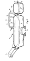
- the intake system 10 for an internal combustion engine shown in Figure 1 has a Air collector 11, more branched off from the air collector 11 suction tubes 12 and an am Air collector 11 arranged pressure accumulator 13.
- the suction pipes 12 open into a Connecting flange 14, which serves the intake system 10 at a not shown here To fix internal combustion engine.
- the suction tubes 12 are the respective Cylinders associated with the internal combustion engine.
- the intake system 10 made of plastic, in particular a PA6 GF30, so a reinforced Polyamide, which can be easily vibration-welded.
- a mounting flange 15 At the air collector 11 is a mounting flange 15, wherein this mounting flange 15 either to further Attaching the intake system 10 or serve to accommodate other functional components can.
- the intake system 10 is here in an upper housing shell part 16 and a divided lower housing part shell 17, wherein between the two division plane 18th runs.
- the two housing part shells 16, 17 are via a vibration welding process welded together in the region of the division plane 18.
- a vacuum line 19 with a valve 20 disposed therein connects the pressure accumulator 13 to the air collector 11.
- the vacuum line 19 on the one hand to a terminal 21 of the Air collector 11 and on the other hand connected to a terminal 22 of the pressure accumulator 13.
- the regularly present in the air collector 11 negative pressure is so here used to generate and maintain a negative pressure in the pressure accumulator 13.
- At the pressure accumulator 13 is still a connection 23 for a not shown here actuating element arranged, wherein the negative pressure in the pressure accumulator 13 is used, the To move actuator.
- FIG. 2 shows a section through the air collector 11 and the pressure accumulator 13 lower portion of the air collector 11 is an inlet 24 through which the through a filter, which is not shown here, enters purified intake air.
- a filter which is not shown here, enters purified intake air.
- both volumes are integral with each other, they are separated by a Bridge 25 separated.
- the web 25 is horizontal, ie transversely to the web direction divided by the division level 18.
Landscapes
- Engineering & Computer Science (AREA)
- Chemical & Material Sciences (AREA)
- Combustion & Propulsion (AREA)
- Mechanical Engineering (AREA)
- General Engineering & Computer Science (AREA)
- Physics & Mathematics (AREA)
- Geometry (AREA)
- Manufacturing & Machinery (AREA)
- Characterised By The Charging Evacuation (AREA)
Applications Claiming Priority (2)
| Application Number | Priority Date | Filing Date | Title |
|---|---|---|---|
| DE20315244U DE20315244U1 (de) | 2003-10-02 | 2003-10-02 | Ansaugsystem mit Druckspeicher |
| DE20315244U | 2003-10-02 |
Publications (1)
| Publication Number | Publication Date |
|---|---|
| EP1520976A2 true EP1520976A2 (fr) | 2005-04-06 |
Family
ID=29762472
Family Applications (1)
| Application Number | Title | Priority Date | Filing Date |
|---|---|---|---|
| EP04103906A Withdrawn EP1520976A2 (fr) | 2003-10-02 | 2004-08-12 | Système d'admission comprenant un accumulateur de pression |
Country Status (4)
| Country | Link |
|---|---|
| US (1) | US20050120991A1 (fr) |
| EP (1) | EP1520976A2 (fr) |
| JP (1) | JP2005113911A (fr) |
| DE (1) | DE20315244U1 (fr) |
Families Citing this family (3)
| Publication number | Priority date | Publication date | Assignee | Title |
|---|---|---|---|---|
| US8176894B2 (en) | 2011-09-22 | 2012-05-15 | Ford Global Technologies, Llc | Vacuum system for an engine |
| US9222405B2 (en) * | 2013-07-08 | 2015-12-29 | Massachusetts Institute Of Technology | Turbocharged single cylinder internal combustion engine using an air capacitor |
| WO2017116377A1 (fr) * | 2015-12-29 | 2017-07-06 | Ford Otomotiv Sanayi A.S. | Refroidisseur d'air de suralimentation refroidi par eau et réservoir à dépression intégré |
Family Cites Families (2)
| Publication number | Priority date | Publication date | Assignee | Title |
|---|---|---|---|---|
| DE19924870A1 (de) * | 1999-05-29 | 2000-11-30 | Mann & Hummel Filter | Saugrohr für die Ansaugluft von Brennkraftmaschinen mit Entlastungsstelle für Druckwellen |
| US6273048B1 (en) * | 1999-12-23 | 2001-08-14 | Daimlerchrsler Corporation | Vacuum reservoir |
-
2003
- 2003-10-02 DE DE20315244U patent/DE20315244U1/de not_active Expired - Lifetime
-
2004
- 2004-08-12 EP EP04103906A patent/EP1520976A2/fr not_active Withdrawn
- 2004-09-21 JP JP2004273308A patent/JP2005113911A/ja active Pending
- 2004-09-30 US US10/953,886 patent/US20050120991A1/en not_active Abandoned
Also Published As
| Publication number | Publication date |
|---|---|
| DE20315244U1 (de) | 2003-12-11 |
| US20050120991A1 (en) | 2005-06-09 |
| JP2005113911A (ja) | 2005-04-28 |
Similar Documents
| Publication | Publication Date | Title |
|---|---|---|
| EP1695753B1 (fr) | Element filtrante avec un tube drainage | |
| EP1306829B1 (fr) | Dispositif pour la transmission du bruit d'un moteur à combustion interne | |
| EP1290332B1 (fr) | Systeme de filtre a air | |
| WO2014202358A1 (fr) | Élément de filtre creux, boîtier de filtre et filtre | |
| DE102016005358A1 (de) | Dichtelement, Ringfilterelement, Ölabscheider sowie Verfahren zum Öffnen des Filtergehäuses eines Ölabscheiders | |
| EP1284356A2 (fr) | Système d'admission pour un moteur à combustion interne | |
| WO2007147598A1 (fr) | Filtre doté d'un insert remplaçable | |
| DE10131108A1 (de) | Filterelement mit Drainagerohr | |
| DE102014011176A1 (de) | Hydraulische Betätigungsvorrichtung für die Betätigung von Stellgliedern in einem Kraftfahrzeuggetriebe | |
| EP1069306B1 (fr) | Tubulure d'admission pour un moteur à combustion | |
| EP1206633A1 (fr) | Dispositif d'aspiration pour moteur a combustion interne | |
| DE19846281A1 (de) | Luftführungssystem, insbesondere Saugsystem einer Verbrennungskraftmaschine | |
| EP1520976A2 (fr) | Système d'admission comprenant un accumulateur de pression | |
| WO1998025022A1 (fr) | Installation de canalisation d'air | |
| EP1422413A2 (fr) | Système d'admission d'air | |
| DE102007031731B4 (de) | Luftfilter zum direkten Anbau an einen Mehrzylinder-Verbrennungsmotor | |
| DE19753390A1 (de) | Stapelförmig angeordneter, schneckenförmiger Krümmer | |
| DE102004025450A1 (de) | Ölwanne für einen Motor und/oder ein Getriebe | |
| EP3755556B1 (fr) | Module de fixation et système de filtre | |
| EP1420160B1 (fr) | Ensemble d'admission d'air pour un moteur à combustion interne | |
| DE10336206B4 (de) | System zur Entfernung von Partikeln aus einem Gasstrom eines Ansaugsystems einer aufgeladenen Brennkraftmaschine | |
| EP1674711A1 (fr) | Moteur suralimenté à diesel avec un système d'injection Common-Rail | |
| DE102010020261A1 (de) | Luftfilter eines Verbrennungsmotors und Zwischenrahmen dafür | |
| DE102004024465A1 (de) | Ansaugsystem | |
| DE10342936B4 (de) | Vorrichtung zur Dämpfung von Druckpulsation und ein mit dieser Vorrichtung ausgestattetes Hydraulikaggregat |
Legal Events
| Date | Code | Title | Description |
|---|---|---|---|
| PUAI | Public reference made under article 153(3) epc to a published international application that has entered the european phase |
Free format text: ORIGINAL CODE: 0009012 |
|
| AK | Designated contracting states |
Kind code of ref document: A2 Designated state(s): AT BE BG CH CY CZ DE DK EE ES FI FR GB GR HU IE IT LI LU MC NL PL PT RO SE SI SK TR |
|
| AX | Request for extension of the european patent |
Extension state: AL HR LT LV MK |
|
| STAA | Information on the status of an ep patent application or granted ep patent |
Free format text: STATUS: THE APPLICATION IS DEEMED TO BE WITHDRAWN |
|
| 18D | Application deemed to be withdrawn |
Effective date: 20070301 |