EP1520828A1 - Elevator apparatus - Google Patents
Elevator apparatus Download PDFInfo
- Publication number
- EP1520828A1 EP1520828A1 EP02743882A EP02743882A EP1520828A1 EP 1520828 A1 EP1520828 A1 EP 1520828A1 EP 02743882 A EP02743882 A EP 02743882A EP 02743882 A EP02743882 A EP 02743882A EP 1520828 A1 EP1520828 A1 EP 1520828A1
- Authority
- EP
- European Patent Office
- Prior art keywords
- control device
- concave portion
- machine room
- lid
- elevator apparatus
- Prior art date
- Legal status (The legal status is an assumption and is not a legal conclusion. Google has not performed a legal analysis and makes no representation as to the accuracy of the status listed.)
- Withdrawn
Links
Images





Classifications
-
- B—PERFORMING OPERATIONS; TRANSPORTING
- B66—HOISTING; LIFTING; HAULING
- B66B—ELEVATORS; ESCALATORS OR MOVING WALKWAYS
- B66B11/00—Main component parts of lifts in, or associated with, buildings or other structures
- B66B11/001—Arrangement of controller, e.g. location
- B66B11/0015—Arrangement of controller, e.g. location in the machine room
-
- B—PERFORMING OPERATIONS; TRANSPORTING
- B66—HOISTING; LIFTING; HAULING
- B66B—ELEVATORS; ESCALATORS OR MOVING WALKWAYS
- B66B11/00—Main component parts of lifts in, or associated with, buildings or other structures
-
- B—PERFORMING OPERATIONS; TRANSPORTING
- B66—HOISTING; LIFTING; HAULING
- B66B—ELEVATORS; ESCALATORS OR MOVING WALKWAYS
- B66B1/00—Control systems of elevators in general
- B66B1/34—Details, e.g. call counting devices, data transmission from car to control system, devices giving information to the control system
Definitions
- the present invention relates to an elevator apparatus in which a driving machine and a control device are arranged in a machine room.
- Fig. 9 is a plan view showing an example of a machine room of a conventional elevator apparatus
- Fig. 10 is a sectional view of the machine room in Fig. 9.
- a machine room 2 is arranged above a hoistway 1 in which a car (not shown) is raised and lowered.
- the machine room 2 includes a floor surface 3, a side wall 4, and a ceiling 5.
- the side wall 4 is provided with a doorway 4a.
- a driving machine (hoisting machine) 6 for raising and lowering the car and a control device (control panel) 7 for controlling the driving machine 6 are arranged on the floor surface 3.
- the driving machine 6 is arranged such that a working space for maintenance inspection is secured in the periphery thereof.
- the control device 7 has a front door 7a, and is arranged such that maintenance inspection work for the control device 7 is performed with the front door 7a being opened.
- the present invention has been made in view of the above, and therefore has an object to obtain an elevator apparatus in which space can be saved in a machine room.
- an elevator apparatus including: a machine room having a floor surface; a driving machine for raising and lowering the car, arranged in the machine room; and a control device for controlling the driving machine, arranged in the machine room, in which: the floor surface of the machine room; is provided with a concave portion and the control device is received in the concave portion.
- Fig. 1 is a plan view showing an inner part of a machine room in an elevator apparatus in accordance with Embodiment 1 of the present invention
- Fig. 2 is a sectional view of the machine room in Fig. 1.
- a machine room 12 is arranged above a hoistway 11 in which a car (not shown) is raised and lowered.
- the machine room 12 has a floor surface 13, a side wall 14, and a ceiling 15.
- the side wall 14 is provided with a doorway 14a.
- a driving machine (hoisting machine) 6 for raising and lowering the car is arranged on the floor surface 13.
- the floor surface 13 is provided with a concave portion 16.
- the concave portion 16 has a bottom surface 16a and an opening portion 16b that faces the bottom surface 16a.
- the concave portion 16 is provided with a flat lid 17 for opening and closing the opening portion 16a.
- Fig. 1 shows a state where the lid 17 is closed
- Fig. 2 shows a state where the lid 17 is opened.
- the lid 17 constitutes a flat surface continuous with the floor surface 13 in the state where the concave portion 16 is closed.
- an operator can step on the lid 17, and a space above the lid 17 serves as a movement space or working space at the time of the maintenance inspection work for the driving machine 6.
- a control device (control panel) 18 for controlling the driving machine 6 and other devices is received in the concave portion 16.
- the control device 18 is received in the concave portion 16 in such fashion as to enable the maintenance inspection thereof to be performed by only opening the lid 17 without the control device 18 being removed from the concave portion 16. That is, the control device 18 is placed on the bottom surface 16a such that a front surface of the control device 18 faces upward.
- an installation space of the control device 18 also serves as the movement space or working space at the time of the maintenance inspection work for the driving machine 6. Therefore, space can be saved in the machine room 12.
- the maintenance inspection work for the control device 18 can be easily performed by only opening the lid 17.
- the lid 17 for opening and closing the opening portion 16b of the concave portion 16 is provided, and thus, a sufficient strength of the lid 17 as a part of a floor for the movement space or working space can be secured without changing the strength of the control device 18. Accordingly, the control device 18 can be protected.
- the opening portion 16b is opened / closed by one lid in Embodiment 1, but may be opened / closed partially by plural lids. In such a case, each of the lids is light in weight to enable opening / closing operations to be carried out with ease.
- the lid 17 which is opened / closed through pivotal movement is shown in Embodiment 1.
- the lid may be provided with a handle gripped by an operator at the time of opening / closing.
- the handle may be temporarily attached to the lid at the time of opening / closing.
- the surface of the lid can be kept flat except at the time of opening / closing.
- the handle cannot be an obstacle to the movement or work made by the operator.
- the lid 17 which is opened / closed through manual operation is shown in Embodiment 1; however, there may be adopted a lid that is driven by an electric motor or the like to be opened / closed.
- the lid may be provided with a transparent window, or the whole lid may be formed of a transparent material. This enables visual inspection of the control device 18 to be carried out with the lid being closed.
- the lid may be provided with an air hole.
- the air hole may be provided with a fan device.
- control device 18 is placed on the bottom surface 16a in Embodiment 1.
- control device may be mounted on a back surface of the lid in the case where the control device is light in weight.
- Fig. 3 is a plan view showing an inner part of a machine room in an elevator apparatus in accordance with Embodiment 2 of the present invention
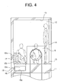
- Fig. 4 is a sectional view of the machine room in Fig. 3.
- Figs. 3 and 4 show a state where the lid 17 is opened.
- a control device (control panel) 19 for controlling the driving machine 6 and other devices is received in the concave portion 16.
- the control device 19 includes a control device main body 19a, which is placed on the bottom surface 16a, and a divided portion 19b, which is mounted on the back surface of the lid 17.
- Other structures in Embodiment 2 are the same as those in Embodiment 1.
- an installation space of the control device 19 also serves as the movement space or working space at the time of the maintenance inspection work for the driving machine 6. Therefore, space can be saved in the machine room 12.
- the divided portion 19b is mounted on the back surface of the lid 17, and thus, the area of the control device 19, which is exposed when the lid 17 is opened, is expanded. That is, the arrangement area of the control device, which can be subjected to maintenance inspection, becomes approximately twice as large as the area in the case where the divided portion 19b is not mounted on the lid 17. Therefore, working performance of the maintenance inspection work for the control device 19 can be improved.
- Fig. 5 is a plan view showing an inner part of a machine room in an elevator apparatus in accordance with Embodiment 3 of the present invention
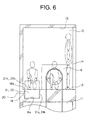
- Fig. 6 is a sectional view of the machine room in Fig. 5.
- a control device (control panel) 20 for controlling the driving machine 6 and other devices is received in the concave portion 16.
- the control device 20 is divided into first and second division units 21 and 22.
- Each of the division units 21 and 22 can be independently removed from the concave portion 16.
- each of the division units 21 and 22 is structured to have a weight at which an operator can carry the unit.
- first and second division units 21 and 22 have casings 21a and 22a, respectively.
- the casings 21a and 22a have casing upper surfaces 21b and 22b, which constitute flat surfaces continuous with the floor surface 13, respectively.
- An operator can step on the casing upper surfaces 21b and 22b, and the casing upper surfaces 21b and 22b each serve as the movement space or working space at the time of the maintenance inspection work for the driving machine 6.
- the casing upper surfaces 21b and 22b are provided with handles 21c and 22c, respectively.
- the handles 21c and 22c are arranged not so as to protrude from the casing upper surfaces 21b and 22b, respectively.
- Other structures in Embodiment 3 are the same as those in Embodiment 1.
- an installation space of the control device 20 also serves as the movement space or working space at the time of the maintenance inspection work for the driving machine 6. Therefore, space can be saved in the machine room 12.
- the casing upper surfaces 21b and 22b which are parts of the control device 20, serve as parts of the floor for the movement space or working space.
- the concave portion 16 is kept open. Therefore, the structure is simple, and also, the maintenance inspection work for the control device 20 can be performed with ease.
- control device 20 is divided into the first and second division units 21 and 22, and each of the division units 21 and 22 can be independently removed from the concave portion 16. Therefore, partial replacement of the control device 20 can be carried out with ease.
- control device 20 is divided into the two division units 21 and 22 in Embodiment 3, but may be divided into three or more division units.
- division units have sizes and shapes different from one another.
- the two division units 21 and 22 are received in the common concave portion 16 in Embodiment 3.
- plural concave portions may be provided to the floor surface to separately receive the division units.
- Fig. 7 is a plan view showing an inner part of a machine room in an elevator apparatus in accordance with Embodiment 4 of the present invention
- Fig. 8 is a sectional view of the machine room in Fig. 7.
- a control device (control panel) 23 for controlling the driving machine 6 and other devices is received in the concave portion 16.
- the control device 23 includes a casing 22a.
- the casing 23a has a casing upper surface 23b that constitutes a flat surface continuous with the floor surface 13. An operator can step on the casing upper surface 23b, and a space above the casing upper surface 23b serves as the movement space or working space at the time of the maintenance inspection work for the driving machine 6.
- a hook 24 is fixed to the ceiling 15 above the concave portion 16.
- the hook 24 is attached with a lifting device 25 for lifting the control device 23 through a lifting accessory 26 such as a wire.
- a lifting device 25 for example, a chain block or a winch is used.
- Other structures in Embodiment 4 are the same as those in Embodiment 1.
- an installation space of the control device 23 also serves as the movement space or working space at the time of the maintenance inspection work for the driving machine 6. Therefore, space can be saved in the machine room 12.
- the casing upper surface 23b which is a part of the control device 23, serves as a part of the floor for the movement space or working space.
- the concave portion 16 is kept open. Therefore, the structure is simple, and also, the maintenance inspection work for the control device 23 can be performed with ease.
- control device 23 can be lifted by the lifting device 25. Therefore, replacement of the whole control device 23 can be performed with ease.
Landscapes
- Engineering & Computer Science (AREA)
- Automation & Control Theory (AREA)
- Civil Engineering (AREA)
- Mechanical Engineering (AREA)
- Structural Engineering (AREA)
- Computer Networks & Wireless Communication (AREA)
- Cage And Drive Apparatuses For Elevators (AREA)
- Elevator Control (AREA)
Abstract
In an elevator apparatus, a driving machine for raising and
lowering a car and a control device for controlling the driving
machine are arranged in a machine room. A floor surface of the machine
room is provided with a concave portion. The control device is
received in the concave portion and the concave portion is provided
with a lid for opening and closing the concave portion. The lid
constitutes a flat surface continuous with the floor surface in
a state where the concave portion is closed.
Description
- The present invention relates to an elevator apparatus in which a driving machine and a control device are arranged in a machine room.
- Fig. 9 is a plan view showing an example of a machine room of a conventional elevator apparatus, and Fig. 10 is a sectional view of the machine room in Fig. 9. In the figures, a
machine room 2 is arranged above a hoistway 1 in which a car (not shown) is raised and lowered. Themachine room 2 includes afloor surface 3, aside wall 4, and aceiling 5. Theside wall 4 is provided with a doorway 4a. - A driving machine (hoisting machine) 6 for raising and lowering the car and a control device (control panel) 7 for controlling the
driving machine 6 are arranged on thefloor surface 3. Thedriving machine 6 is arranged such that a working space for maintenance inspection is secured in the periphery thereof. Further, thecontrol device 7 has afront door 7a, and is arranged such that maintenance inspection work for thecontrol device 7 is performed with thefront door 7a being opened. - In the above-described conventional elevator apparatus, a working space for maintenance inspection of the
driving machine 6 and thecontrol device 7 and a movement space for an operator at the time of the maintenance inspection work need to be secured in themachine room 2 besides installation spaces of thedriving machine 6 and thecontrol device 7. Therefore, a floor area of themachine room 2 becomes large. - The present invention has been made in view of the above, and therefore has an object to obtain an elevator apparatus in which space can be saved in a machine room.
- According to the present invention, there is provided an elevator apparatus including: a machine room having a floor surface; a driving machine for raising and lowering the car, arranged in the machine room; and a control device for controlling the driving machine, arranged in the machine room, in which: the floor surface of the machine room; is provided with a concave portion and the control device is received in the concave portion.
-
- Fig. 1 is a plan view showing an inner part of a machine room in an elevator apparatus in accordance with Embodiment 1 of the present invention;
- Fig. 2 is a sectional view of the machine room in Fig. 1;
- Fig. 3 is a plan view showing an inner part of a machine room
in an elevator apparatus in accordance with
Embodiment 2 of the present invention; - Fig. 4 is a sectional view of the machine room in Fig. 3;
- Fig. 5 is a plan view showing an inner part of a machine room
in an elevator apparatus in accordance with
Embodiment 3 of the present invention; - Fig. 6 is a sectional view of the machine room in Fig. 5;
- Fig. 7 is a plan view showing an inner part of a machine room
in an elevator apparatus in accordance with
Embodiment 4 of the present invention; - Fig. 8 is a sectional view of the machine room in Fig. 7;
- Fig. 9 is a plan view showing an example of a machine room in a conventional elevator apparatus; and
- Fig. 10 is a sectional view of the machine room shown in Fig. 9.
-
- Hereinafter, description will be made of preferred embodiments of the present invention with reference to the accompanying drawings.
- Fig. 1 is a plan view showing an inner part of a machine room in an elevator apparatus in accordance with Embodiment 1 of the present invention, and Fig. 2 is a sectional view of the machine room in Fig. 1. In the figures, a
machine room 12 is arranged above a hoistway 11 in which a car (not shown) is raised and lowered. Themachine room 12 has afloor surface 13, aside wall 14, and aceiling 15. Theside wall 14 is provided with adoorway 14a. A driving machine (hoisting machine) 6 for raising and lowering the car is arranged on thefloor surface 13. - The
floor surface 13 is provided with aconcave portion 16. Theconcave portion 16 has abottom surface 16a and anopening portion 16b that faces thebottom surface 16a. Theconcave portion 16 is provided with aflat lid 17 for opening and closing theopening portion 16a. Fig. 1 shows a state where thelid 17 is closed, and Fig. 2 shows a state where thelid 17 is opened. - Further, the
lid 17 constitutes a flat surface continuous with thefloor surface 13 in the state where theconcave portion 16 is closed. In addition, an operator can step on thelid 17, and a space above thelid 17 serves as a movement space or working space at the time of the maintenance inspection work for thedriving machine 6. - A control device (control panel) 18 for controlling the
driving machine 6 and other devices is received in theconcave portion 16. Thecontrol device 18 is received in theconcave portion 16 in such fashion as to enable the maintenance inspection thereof to be performed by only opening thelid 17 without thecontrol device 18 being removed from theconcave portion 16. That is, thecontrol device 18 is placed on thebottom surface 16a such that a front surface of thecontrol device 18 faces upward. - In the above-described elevator apparatus, an installation space of the
control device 18 also serves as the movement space or working space at the time of the maintenance inspection work for thedriving machine 6. Therefore, space can be saved in themachine room 12. - Further, the maintenance inspection work for the
control device 18 can be easily performed by only opening thelid 17. - Moreover, the
lid 17 for opening and closing theopening portion 16b of theconcave portion 16 is provided, and thus, a sufficient strength of thelid 17 as a part of a floor for the movement space or working space can be secured without changing the strength of thecontrol device 18. Accordingly, thecontrol device 18 can be protected. - Note that the
opening portion 16b is opened / closed by one lid in Embodiment 1, but may be opened / closed partially by plural lids. In such a case, each of the lids is light in weight to enable opening / closing operations to be carried out with ease. - Further, the
lid 17 which is opened / closed through pivotal movement is shown in Embodiment 1. However, there may be adopted a lid that is opened / closed through sliding movement in parallel with thefloor surface 13 or a lid that is completely removed from thefloor surface 13. - Moreover, the lid may be provided with a handle gripped by an operator at the time of opening / closing. In addition, the handle may be temporarily attached to the lid at the time of opening / closing. In this case, the surface of the lid can be kept flat except at the time of opening / closing. Thus, the handle cannot be an obstacle to the movement or work made by the operator.
- Furthermore, the
lid 17 which is opened / closed through manual operation is shown in Embodiment 1; however, there may be adopted a lid that is driven by an electric motor or the like to be opened / closed. - Moreover, the lid may be provided with a transparent window, or the whole lid may be formed of a transparent material. This enables visual inspection of the
control device 18 to be carried out with the lid being closed. - Further, the lid may be provided with an air hole. In addition, the air hole may be provided with a fan device.
- Furthermore, the
control device 18 is placed on thebottom surface 16a in Embodiment 1. However, the control device may be mounted on a back surface of the lid in the case where the control device is light in weight. - Next, Fig. 3 is a plan view showing an inner part of a machine room in an elevator apparatus in accordance with
Embodiment 2 of the present invention, and Fig. 4 is a sectional view of the machine room in Fig. 3. Further, Figs. 3 and 4 show a state where thelid 17 is opened. In the figures, a control device (control panel) 19 for controlling the drivingmachine 6 and other devices is received in theconcave portion 16. Thecontrol device 19 includes a control devicemain body 19a, which is placed on thebottom surface 16a, and a dividedportion 19b, which is mounted on the back surface of thelid 17. Other structures inEmbodiment 2 are the same as those in Embodiment 1. - In the above-described elevator apparatus, an installation space of the
control device 19 also serves as the movement space or working space at the time of the maintenance inspection work for the drivingmachine 6. Therefore, space can be saved in themachine room 12. - Further, the divided
portion 19b is mounted on the back surface of thelid 17, and thus, the area of thecontrol device 19, which is exposed when thelid 17 is opened, is expanded. That is, the arrangement area of the control device, which can be subjected to maintenance inspection, becomes approximately twice as large as the area in the case where the dividedportion 19b is not mounted on thelid 17. Therefore, working performance of the maintenance inspection work for thecontrol device 19 can be improved. - Next, Fig. 5 is a plan view showing an inner part of a machine room in an elevator apparatus in accordance with
Embodiment 3 of the present invention, and Fig. 6 is a sectional view of the machine room in Fig. 5. In the figures, a control device (control panel) 20 for controlling the drivingmachine 6 and other devices is received in theconcave portion 16. Thecontrol device 20 is divided into first andsecond division units division units concave portion 16. Further, each of thedivision units - Further, the first and
second division units casings 21a and 22a, respectively. Thecasings 21a and 22a have casingupper surfaces floor surface 13, respectively. An operator can step on the casingupper surfaces upper surfaces machine 6. - Further, the casing
upper surfaces handles handles upper surfaces Embodiment 3 are the same as those in Embodiment 1. - In the above-described elevator apparatus, an installation space of the
control device 20 also serves as the movement space or working space at the time of the maintenance inspection work for the drivingmachine 6. Therefore, space can be saved in themachine room 12. - Further, the casing
upper surfaces control device 20, serve as parts of the floor for the movement space or working space. Thus, theconcave portion 16 is kept open. Therefore, the structure is simple, and also, the maintenance inspection work for thecontrol device 20 can be performed with ease. - Moreover, the
control device 20 is divided into the first andsecond division units division units concave portion 16. Therefore, partial replacement of thecontrol device 20 can be carried out with ease. - Note that the
control device 20 is divided into the twodivision units Embodiment 3, but may be divided into three or more division units. - Further, the division units have sizes and shapes different from one another.
- Furthermore, the two
division units concave portion 16 inEmbodiment 3. However, plural concave portions may be provided to the floor surface to separately receive the division units. - Next, Fig. 7 is a plan view showing an inner part of a machine room in an elevator apparatus in accordance with
Embodiment 4 of the present invention, and Fig. 8 is a sectional view of the machine room in Fig. 7. In the figures, a control device (control panel) 23 for controlling the drivingmachine 6 and other devices is received in theconcave portion 16. Thecontrol device 23 includes a casing 22a. - The
casing 23a has a casingupper surface 23b that constitutes a flat surface continuous with thefloor surface 13. An operator can step on the casingupper surface 23b, and a space above the casingupper surface 23b serves as the movement space or working space at the time of the maintenance inspection work for the drivingmachine 6. - A
hook 24 is fixed to theceiling 15 above theconcave portion 16. Thehook 24 is attached with alifting device 25 for lifting thecontrol device 23 through a liftingaccessory 26 such as a wire. As thelifting device 25, for example, a chain block or a winch is used. Other structures inEmbodiment 4 are the same as those in Embodiment 1. - In the above-described elevator apparatus, an installation space of the
control device 23 also serves as the movement space or working space at the time of the maintenance inspection work for the drivingmachine 6. Therefore, space can be saved in themachine room 12. - Further, the casing
upper surface 23b, which is a part of thecontrol device 23, serves as a part of the floor for the movement space or working space. Thus, theconcave portion 16 is kept open. Therefore, the structure is simple, and also, the maintenance inspection work for thecontrol device 23 can be performed with ease. - Moreover, the
control device 23 can be lifted by the liftingdevice 25. Therefore, replacement of thewhole control device 23 can be performed with ease.
Claims (6)
- An elevator apparatus, comprising:wherein:a machine room having a floor surface;a driving machine for raising and lowering a car, arranged in the machine room; anda control device for controlling the driving machine, arranged in the machine room,the floor surface of the machine room is provided with a concave portion; andthe control device is received in the concave portion.
- An elevator apparatus according to claim 1, wherein the concave portion is provided with a lid for opening and closing the concave portion, and the lid constitutes a flat surface continuous with the floor surface in a state where the concave portion is closed.
- An elevator apparatus according to claim 2, wherein a part of the control device is mounted on a back surface of the lid.
- An elevator apparatus according to claim 1, wherein the control device has a casing, and the casing has a casing upper surface that constitutes a flat surface continuous with the floor surface.
- An elevator apparatus according to claim 1, wherein the control device is divided into plural division units, and each of the division units can be independently removed from the concave portion.
- An elevator apparatus according to claim 1, wherein a lifting device that lifts the control device is provided above the concave portion in the machine room.
Applications Claiming Priority (1)
| Application Number | Priority Date | Filing Date | Title |
|---|---|---|---|
| PCT/JP2002/006954 WO2004005175A1 (en) | 2002-07-09 | 2002-07-09 | Elevator apparatus |
Publications (1)
| Publication Number | Publication Date |
|---|---|
| EP1520828A1 true EP1520828A1 (en) | 2005-04-06 |
Family
ID=30022631
Family Applications (1)
| Application Number | Title | Priority Date | Filing Date |
|---|---|---|---|
| EP02743882A Withdrawn EP1520828A1 (en) | 2002-07-09 | 2002-07-09 | Elevator apparatus |
Country Status (5)
| Country | Link |
|---|---|
| EP (1) | EP1520828A1 (en) |
| JP (1) | JPWO2004005175A1 (en) |
| KR (1) | KR20040029028A (en) |
| CN (1) | CN1525935A (en) |
| WO (1) | WO2004005175A1 (en) |
Family Cites Families (4)
| Publication number | Priority date | Publication date | Assignee | Title |
|---|---|---|---|---|
| JPS60137783A (en) * | 1983-12-27 | 1985-07-22 | 株式会社東芝 | Elevator controller |
| JP3399161B2 (en) * | 1995-06-15 | 2003-04-21 | 三菱電機株式会社 | Elevator equipment |
| JP2001002353A (en) * | 1999-06-24 | 2001-01-09 | Toshiba Corp | Elevator equipment |
| JP2001002352A (en) * | 1999-06-24 | 2001-01-09 | Toshiba Corp | Elevator equipment |
-
2002
- 2002-07-09 JP JP2004519191A patent/JPWO2004005175A1/en active Pending
- 2002-07-09 EP EP02743882A patent/EP1520828A1/en not_active Withdrawn
- 2002-07-09 CN CNA028137663A patent/CN1525935A/en active Pending
- 2002-07-09 WO PCT/JP2002/006954 patent/WO2004005175A1/en not_active Ceased
- 2002-07-09 KR KR10-2004-7002725A patent/KR20040029028A/en not_active Ceased
Non-Patent Citations (1)
| Title |
|---|
| See references of WO2004005175A1 * |
Also Published As
| Publication number | Publication date |
|---|---|
| JPWO2004005175A1 (en) | 2005-11-04 |
| CN1525935A (en) | 2004-09-01 |
| WO2004005175A1 (en) | 2004-01-15 |
| KR20040029028A (en) | 2004-04-03 |
Similar Documents
| Publication | Publication Date | Title |
|---|---|---|
| CN109476460B (en) | Elevator installation for safety maintenance work | |
| EP3484805A1 (en) | Elevator arrangement with low headroom | |
| US11560291B2 (en) | Elevator arrangement to open the roof of an elevator car | |
| JP2000247560A (en) | Elevator equipment | |
| JP4353898B2 (en) | Elevator equipment | |
| WO2018011460A1 (en) | Elevator arrangement | |
| EP1520828A1 (en) | Elevator apparatus | |
| JP4403142B2 (en) | Elevator apparatus drive unit, elevator apparatus, elevator apparatus installation method, and elevator apparatus maintenance and inspection method | |
| JP2007091430A (en) | Elevator device | |
| CA2529566A1 (en) | Lift cage with cage electrical system integrated in the cage roof and method of mounting a lift installation | |
| JPH0318569A (en) | Control panel for elevator | |
| JP2008195523A (en) | Elevator equipment | |
| JP2003201074A (en) | Elevator containment rescue method and apparatus | |
| JP4262340B2 (en) | Elevator control device | |
| JP3399161B2 (en) | Elevator equipment | |
| JPH07237848A (en) | Elevator installation method | |
| CN214217979U (en) | Tower crane toilet device | |
| JP2001106459A (en) | Elevator car | |
| JP3809142B2 (en) | Base device for elevator for seismic isolation building | |
| JP2012171756A (en) | Elevator apparatus | |
| CN120097187A (en) | Elevator car and elevator | |
| JPH10250964A (en) | How to install a passenger conveyor frame | |
| EP1657206A3 (en) | Elevator car with simplified assembly | |
| EP1329410A1 (en) | Elevator and car position confirmation device for the elevator | |
| JP2006248630A (en) | Elevator car device |
Legal Events
| Date | Code | Title | Description |
|---|---|---|---|
| PUAI | Public reference made under article 153(3) epc to a published international application that has entered the european phase |
Free format text: ORIGINAL CODE: 0009012 |
|
| 17P | Request for examination filed |
Effective date: 20040115 |
|
| AK | Designated contracting states |
Kind code of ref document: A1 Designated state(s): AT BE BG CH CY CZ DE DK EE ES FI FR GB GR IE IT LI LU MC NL PT SE SK TR |
|
| STAA | Information on the status of an ep patent application or granted ep patent |
Free format text: STATUS: THE APPLICATION HAS BEEN WITHDRAWN |
|
| 18W | Application withdrawn |
Effective date: 20050610 |