EP1520745B1 - Method and device for Recognising and adjusting left-hand or right hand driving - Google Patents
Method and device for Recognising and adjusting left-hand or right hand driving Download PDFInfo
- Publication number
- EP1520745B1 EP1520745B1 EP04022036A EP04022036A EP1520745B1 EP 1520745 B1 EP1520745 B1 EP 1520745B1 EP 04022036 A EP04022036 A EP 04022036A EP 04022036 A EP04022036 A EP 04022036A EP 1520745 B1 EP1520745 B1 EP 1520745B1
- Authority
- EP
- European Patent Office
- Prior art keywords
- detected
- vehicle
- hand driving
- objects
- respect
- Prior art date
- Legal status (The legal status is an assumption and is not a legal conclusion. Google has not performed a legal analysis and makes no representation as to the accuracy of the status listed.)
- Active
Links
- 238000000034 method Methods 0.000 title claims description 32
- 238000001514 detection method Methods 0.000 claims description 21
- 230000003044 adaptive effect Effects 0.000 claims description 12
- 230000006870 function Effects 0.000 description 7
- 230000005484 gravity Effects 0.000 description 4
- 238000010586 diagram Methods 0.000 description 3
- 230000001133 acceleration Effects 0.000 description 2
- 238000011161 development Methods 0.000 description 2
- 230000018109 developmental process Effects 0.000 description 2
- 239000000446 fuel Substances 0.000 description 2
- 238000002347 injection Methods 0.000 description 2
- 239000007924 injection Substances 0.000 description 2
- 230000001105 regulatory effect Effects 0.000 description 2
- 238000012935 Averaging Methods 0.000 description 1
- 230000004888 barrier function Effects 0.000 description 1
- 238000002485 combustion reaction Methods 0.000 description 1
- 230000008094 contradictory effect Effects 0.000 description 1
- 238000005286 illumination Methods 0.000 description 1
- 230000005855 radiation Effects 0.000 description 1
- 238000002604 ultrasonography Methods 0.000 description 1
Images

Classifications
-
- G—PHYSICS
- G01—MEASURING; TESTING
- G01S—RADIO DIRECTION-FINDING; RADIO NAVIGATION; DETERMINING DISTANCE OR VELOCITY BY USE OF RADIO WAVES; LOCATING OR PRESENCE-DETECTING BY USE OF THE REFLECTION OR RERADIATION OF RADIO WAVES; ANALOGOUS ARRANGEMENTS USING OTHER WAVES
- G01S7/00—Details of systems according to groups G01S13/00, G01S15/00, G01S17/00
- G01S7/02—Details of systems according to groups G01S13/00, G01S15/00, G01S17/00 of systems according to group G01S13/00
- G01S7/41—Details of systems according to groups G01S13/00, G01S15/00, G01S17/00 of systems according to group G01S13/00 using analysis of echo signal for target characterisation; Target signature; Target cross-section
- G01S7/411—Identification of targets based on measurements of radar reflectivity
-
- B—PERFORMING OPERATIONS; TRANSPORTING
- B60—VEHICLES IN GENERAL
- B60K—ARRANGEMENT OR MOUNTING OF PROPULSION UNITS OR OF TRANSMISSIONS IN VEHICLES; ARRANGEMENT OR MOUNTING OF PLURAL DIVERSE PRIME-MOVERS IN VEHICLES; AUXILIARY DRIVES FOR VEHICLES; INSTRUMENTATION OR DASHBOARDS FOR VEHICLES; ARRANGEMENTS IN CONNECTION WITH COOLING, AIR INTAKE, GAS EXHAUST OR FUEL SUPPLY OF PROPULSION UNITS IN VEHICLES
- B60K31/00—Vehicle fittings, acting on a single sub-unit only, for automatically controlling vehicle speed, i.e. preventing speed from exceeding an arbitrarily established velocity or maintaining speed at a particular velocity, as selected by the vehicle operator
- B60K31/0008—Vehicle fittings, acting on a single sub-unit only, for automatically controlling vehicle speed, i.e. preventing speed from exceeding an arbitrarily established velocity or maintaining speed at a particular velocity, as selected by the vehicle operator including means for detecting potential obstacles in vehicle path
-
- G—PHYSICS
- G01—MEASURING; TESTING
- G01S—RADIO DIRECTION-FINDING; RADIO NAVIGATION; DETERMINING DISTANCE OR VELOCITY BY USE OF RADIO WAVES; LOCATING OR PRESENCE-DETECTING BY USE OF THE REFLECTION OR RERADIATION OF RADIO WAVES; ANALOGOUS ARRANGEMENTS USING OTHER WAVES
- G01S13/00—Systems using the reflection or reradiation of radio waves, e.g. radar systems; Analogous systems using reflection or reradiation of waves whose nature or wavelength is irrelevant or unspecified
- G01S13/02—Systems using reflection of radio waves, e.g. primary radar systems; Analogous systems
- G01S13/50—Systems of measurement based on relative movement of target
-
- G—PHYSICS
- G01—MEASURING; TESTING
- G01S—RADIO DIRECTION-FINDING; RADIO NAVIGATION; DETERMINING DISTANCE OR VELOCITY BY USE OF RADIO WAVES; LOCATING OR PRESENCE-DETECTING BY USE OF THE REFLECTION OR RERADIATION OF RADIO WAVES; ANALOGOUS ARRANGEMENTS USING OTHER WAVES
- G01S13/00—Systems using the reflection or reradiation of radio waves, e.g. radar systems; Analogous systems using reflection or reradiation of waves whose nature or wavelength is irrelevant or unspecified
- G01S13/88—Radar or analogous systems specially adapted for specific applications
- G01S13/93—Radar or analogous systems specially adapted for specific applications for anti-collision purposes
- G01S13/931—Radar or analogous systems specially adapted for specific applications for anti-collision purposes of land vehicles
-
- B—PERFORMING OPERATIONS; TRANSPORTING
- B60—VEHICLES IN GENERAL
- B60W—CONJOINT CONTROL OF VEHICLE SUB-UNITS OF DIFFERENT TYPE OR DIFFERENT FUNCTION; CONTROL SYSTEMS SPECIALLY ADAPTED FOR HYBRID VEHICLES; ROAD VEHICLE DRIVE CONTROL SYSTEMS FOR PURPOSES NOT RELATED TO THE CONTROL OF A PARTICULAR SUB-UNIT
- B60W2554/00—Input parameters relating to objects
- B60W2554/40—Dynamic objects, e.g. animals, windblown objects
- B60W2554/404—Characteristics
- B60W2554/4041—Position
-
- B—PERFORMING OPERATIONS; TRANSPORTING
- B60—VEHICLES IN GENERAL
- B60W—CONJOINT CONTROL OF VEHICLE SUB-UNITS OF DIFFERENT TYPE OR DIFFERENT FUNCTION; CONTROL SYSTEMS SPECIALLY ADAPTED FOR HYBRID VEHICLES; ROAD VEHICLE DRIVE CONTROL SYSTEMS FOR PURPOSES NOT RELATED TO THE CONTROL OF A PARTICULAR SUB-UNIT
- B60W2554/00—Input parameters relating to objects
- B60W2554/40—Dynamic objects, e.g. animals, windblown objects
- B60W2554/404—Characteristics
- B60W2554/4042—Longitudinal speed
-
- B—PERFORMING OPERATIONS; TRANSPORTING
- B60—VEHICLES IN GENERAL
- B60W—CONJOINT CONTROL OF VEHICLE SUB-UNITS OF DIFFERENT TYPE OR DIFFERENT FUNCTION; CONTROL SYSTEMS SPECIALLY ADAPTED FOR HYBRID VEHICLES; ROAD VEHICLE DRIVE CONTROL SYSTEMS FOR PURPOSES NOT RELATED TO THE CONTROL OF A PARTICULAR SUB-UNIT
- B60W2554/00—Input parameters relating to objects
- B60W2554/80—Spatial relation or speed relative to objects
- B60W2554/804—Relative longitudinal speed
-
- B—PERFORMING OPERATIONS; TRANSPORTING
- B60—VEHICLES IN GENERAL
- B60W—CONJOINT CONTROL OF VEHICLE SUB-UNITS OF DIFFERENT TYPE OR DIFFERENT FUNCTION; CONTROL SYSTEMS SPECIALLY ADAPTED FOR HYBRID VEHICLES; ROAD VEHICLE DRIVE CONTROL SYSTEMS FOR PURPOSES NOT RELATED TO THE CONTROL OF A PARTICULAR SUB-UNIT
- B60W2555/00—Input parameters relating to exterior conditions, not covered by groups B60W2552/00, B60W2554/00
- B60W2555/60—Traffic rules, e.g. speed limits or right of way
- B60W2555/80—Country specific, e.g. driver age limits or right hand drive
-
- G—PHYSICS
- G01—MEASURING; TESTING
- G01S—RADIO DIRECTION-FINDING; RADIO NAVIGATION; DETERMINING DISTANCE OR VELOCITY BY USE OF RADIO WAVES; LOCATING OR PRESENCE-DETECTING BY USE OF THE REFLECTION OR RERADIATION OF RADIO WAVES; ANALOGOUS ARRANGEMENTS USING OTHER WAVES
- G01S13/00—Systems using the reflection or reradiation of radio waves, e.g. radar systems; Analogous systems using reflection or reradiation of waves whose nature or wavelength is irrelevant or unspecified
- G01S13/88—Radar or analogous systems specially adapted for specific applications
- G01S13/93—Radar or analogous systems specially adapted for specific applications for anti-collision purposes
- G01S13/931—Radar or analogous systems specially adapted for specific applications for anti-collision purposes of land vehicles
- G01S2013/932—Radar or analogous systems specially adapted for specific applications for anti-collision purposes of land vehicles using own vehicle data, e.g. ground speed, steering wheel direction
-
- G—PHYSICS
- G01—MEASURING; TESTING
- G01S—RADIO DIRECTION-FINDING; RADIO NAVIGATION; DETERMINING DISTANCE OR VELOCITY BY USE OF RADIO WAVES; LOCATING OR PRESENCE-DETECTING BY USE OF THE REFLECTION OR RERADIATION OF RADIO WAVES; ANALOGOUS ARRANGEMENTS USING OTHER WAVES
- G01S13/00—Systems using the reflection or reradiation of radio waves, e.g. radar systems; Analogous systems using reflection or reradiation of waves whose nature or wavelength is irrelevant or unspecified
- G01S13/88—Radar or analogous systems specially adapted for specific applications
- G01S13/93—Radar or analogous systems specially adapted for specific applications for anti-collision purposes
- G01S13/931—Radar or analogous systems specially adapted for specific applications for anti-collision purposes of land vehicles
- G01S2013/9321—Velocity regulation, e.g. cruise control
-
- G—PHYSICS
- G01—MEASURING; TESTING
- G01S—RADIO DIRECTION-FINDING; RADIO NAVIGATION; DETERMINING DISTANCE OR VELOCITY BY USE OF RADIO WAVES; LOCATING OR PRESENCE-DETECTING BY USE OF THE REFLECTION OR RERADIATION OF RADIO WAVES; ANALOGOUS ARRANGEMENTS USING OTHER WAVES
- G01S13/00—Systems using the reflection or reradiation of radio waves, e.g. radar systems; Analogous systems using reflection or reradiation of waves whose nature or wavelength is irrelevant or unspecified
- G01S13/88—Radar or analogous systems specially adapted for specific applications
- G01S13/93—Radar or analogous systems specially adapted for specific applications for anti-collision purposes
- G01S13/931—Radar or analogous systems specially adapted for specific applications for anti-collision purposes of land vehicles
- G01S2013/9323—Alternative operation using light waves
-
- G—PHYSICS
- G01—MEASURING; TESTING
- G01S—RADIO DIRECTION-FINDING; RADIO NAVIGATION; DETERMINING DISTANCE OR VELOCITY BY USE OF RADIO WAVES; LOCATING OR PRESENCE-DETECTING BY USE OF THE REFLECTION OR RERADIATION OF RADIO WAVES; ANALOGOUS ARRANGEMENTS USING OTHER WAVES
- G01S13/00—Systems using the reflection or reradiation of radio waves, e.g. radar systems; Analogous systems using reflection or reradiation of waves whose nature or wavelength is irrelevant or unspecified
- G01S13/88—Radar or analogous systems specially adapted for specific applications
- G01S13/93—Radar or analogous systems specially adapted for specific applications for anti-collision purposes
- G01S13/931—Radar or analogous systems specially adapted for specific applications for anti-collision purposes of land vehicles
- G01S2013/9324—Alternative operation using ultrasonic waves
-
- G—PHYSICS
- G01—MEASURING; TESTING
- G01S—RADIO DIRECTION-FINDING; RADIO NAVIGATION; DETERMINING DISTANCE OR VELOCITY BY USE OF RADIO WAVES; LOCATING OR PRESENCE-DETECTING BY USE OF THE REFLECTION OR RERADIATION OF RADIO WAVES; ANALOGOUS ARRANGEMENTS USING OTHER WAVES
- G01S13/00—Systems using the reflection or reradiation of radio waves, e.g. radar systems; Analogous systems using reflection or reradiation of waves whose nature or wavelength is irrelevant or unspecified
- G01S13/88—Radar or analogous systems specially adapted for specific applications
- G01S13/93—Radar or analogous systems specially adapted for specific applications for anti-collision purposes
- G01S13/931—Radar or analogous systems specially adapted for specific applications for anti-collision purposes of land vehicles
- G01S2013/9325—Radar or analogous systems specially adapted for specific applications for anti-collision purposes of land vehicles for inter-vehicle distance regulation, e.g. navigating in platoons
-
- G—PHYSICS
- G01—MEASURING; TESTING
- G01S—RADIO DIRECTION-FINDING; RADIO NAVIGATION; DETERMINING DISTANCE OR VELOCITY BY USE OF RADIO WAVES; LOCATING OR PRESENCE-DETECTING BY USE OF THE REFLECTION OR RERADIATION OF RADIO WAVES; ANALOGOUS ARRANGEMENTS USING OTHER WAVES
- G01S13/00—Systems using the reflection or reradiation of radio waves, e.g. radar systems; Analogous systems using reflection or reradiation of waves whose nature or wavelength is irrelevant or unspecified
- G01S13/88—Radar or analogous systems specially adapted for specific applications
- G01S13/93—Radar or analogous systems specially adapted for specific applications for anti-collision purposes
- G01S13/931—Radar or analogous systems specially adapted for specific applications for anti-collision purposes of land vehicles
- G01S2013/9327—Sensor installation details
- G01S2013/93271—Sensor installation details in the front of the vehicles
Definitions
- the present invention relates to an apparatus and a method for the automatic detection and adjustment of the sense of traffic in an adaptive distance and speed control, in particular for a motor vehicle.
- the adaptive distance and speed controller the relative speed of detected objects, the lateral offset of the detected objects with respect to the vehicle longitudinal axis and the speed of the own vehicle is supplied.
- a distance and velocity controller which emits radar radiation and receives the partial waves reflected on objects.
- FMCW modulation method it is possible to determine the relative speed and the distance of the detected objects from the received radar sub-waves and to regulate the speed of the vehicle as a function thereof.
- a speed control is carried out in the sense of a constant distance control and in the absence of a preceding vehicle carried out a speed control in terms of constant speed control.
- a method and a device for detecting right or left traffic according to the preamble of method claim 1 and the device claim 9 is known.
- the predominant orientation of the traffic flow is determined by other vehicles that accommodate the vehicle mentioned.
- a frequency distribution is formed as a function of a lateral, preferably directional, distance Y, a center of gravity S of this frequency distribution is determined and it is checked on which side of the controlled vehicle this center of gravity S is located.
- From the DE 198 28160 A1 is a method for automatically recognizing the main directional lane in a multi-lane route with the steps of detecting the speed of a first vehicle and detecting the distance of the first vehicle from an obstacle.
- an additional determination of the vector components of the relative speed of the first vehicle relative to the obstacle in a reference system is carried out and a determination of the main directional roadway from one of the detected vector components of the speed is performed.
- the said method is used in a vehicle as part of an adaptive cruise control.
- the predominant orientation of the traffic flow is determined by other vehicles that accommodate the vehicle mentioned.
- a frequency distribution is formed as a function of a lateral, preferably directional, distance y, a center of gravity S of this frequency distribution is determined and it is checked on which side of the controlled vehicle this center of gravity S is located.
- Object of the present invention is to provide a method and an associated device that allow to detect the currently prevailing sense of traffic with high security and adjust the distance and speed controller accordingly.
- Knowledge of the sense of traffic is of great importance for the distance and speed controller since individual controller functions require knowledge of the sense of traffic.
- slower vehicles than the regulated vehicle may only be overtaken on the side specified for faster traffic.
- This is, for example, inlitissinnigem traffic, as it exists in Central Europe, only on the left lane possible, therefore allowed on left hand traffic only on the right lane. According to the invention this is achieved by the features of the independent claims.
- Advantageous developments and refinements emerge from the subclaims.
- lateral lateral offset or “lateral lateral offset” is used for the shortest distance that the object has to the extended vehicle longitudinal axis.
- a left-sided or right-sided, lateral transverse offset is also defined, wherein a left-lateral lateral offset means that the object is on the viewed in the direction of travel of the own vehicle, left half-plane of the elongated vehicle axis or at a right-lateral lateral offset, the object on the seen in the direction of travel of the own vehicle right half-plane, which is bounded by the extended vehicle longitudinal axis is located.
- a first v-axis can be provided in the direction of travel, ie in the direction of the extended vehicle longitudinal axis and a further coordinate which is rectangular thereto, the q-axis, which defines the transverse offset. If this is provided, for example, in such a way that the positive direction of the transverse offset coordinate points in the direction of left-lateral lateral offset and shows the negative lateral offset coordinate in the direction of right lateral lateral offsets, the left lateral lateral offsets can also be referred to as positive lateral lateral offsets and the right lateral lateral offsets Refer to transverse offsets as negative lateral cross offsets.
- positive relative velocities are used when a moving object moves in the same direction as the own vehicle but has a greater absolute speed than the own vehicle.
- negative relative velocities are defined for objects that move either in the same direction of travel as their own vehicle, but have a lower absolute velocity, or used for objects that move in the opposite direction of their own vehicle movement direction and can have any speed.
- the term "right-hand traffic” is used for traffic senses in which road users drive on the right-hand side of the roadway, as is for example intended in Central Europe, the United States of America or most other countries in the world.
- the term "left-hand traffic”, on the other hand, is used for traffic senses in which the vehicles drive on the left-hand side of the roadway, as is the case for example in the United Kingdom, Japan or Australia.
- a right-hand traffic is advantageously detected when the detected, oncoming, moving objects have a left-lateral lateral offset with respect to the vehicle longitudinal axis, and a left-hand traffic is detected if a right-lateral lateral offset is detected.
- an oncoming, moving object is detected if it has a negative relative speed and the amount of relative speed is greater than the amount of the vehicle's own speed.
- a right-hand traffic is advantageously detected if the detected, stationary objects whose absolute value of the lateral transverse offset is smaller than a lane width have a right-lateral lateral offset with respect to the vehicle longitudinal axis and a left-hand traffic is detected if the detected stationary objects whose amount of lateral lateral offset is smaller than a lane width, have a right lateral lateral offset with respect to the vehicle longitudinal axis.
- a stationary object is detected when the amount of the relative speed corresponds approximately to the amount of the own vehicle speed.
- a right-hand traffic is advantageously detected if the detected mobile faster objects have a left-lateral lateral offset with respect to the vehicle longitudinal axis and a left-hand traffic detected if the detected, movable, faster objects have a right-lateral lateral offset with respect to the vehicle longitudinal axis.
- a right-hand traffic is advantageously detected when the detected, movable, slower objects have a right-lateral lateral offset with respect to the vehicle longitudinal axis and a left-hand traffic recognized when the detected, movable, slower objects have a left-lateral lateral offset with respect to the vehicle longitudinal axis.
- a movable, slower object is detected when the relative speed with respect to the own vehicle is negative and the amount of the relative speed is between zero and the amount of the own vehicle speed.
- the detection methods for right and left traffic are mutually checked for plausibility.
- the traffic awareness is based on the Viewing detected, oncoming, moving targets, the detection of the sense of traffic by means of the detected, stationary objects, the detection of the sense of traffic by means of the detected, mobile, faster objects and the traffic awareness by means of the detected, moving, slower objects considered.
- Each of these recognition methods can result in left or right-hand traffic or no statement.
- the detection of moving, faster or slower objects on adjacent lanes is only possible on multi-lane roads, with multi-lane roads, the detection of oncoming, moving targets may be impossible.
- the currently detected sense of traffic is displayed to the driver by means of a display device.
- This can be indicated for example by the illumination of a control lamp or by means of a plain text display or a symbolic display in a display of the dashboard.
- the means for determining the distance, the relative velocity of detected objects and the azimuthal object angle, under the object has been detected, from which the lateral offset of the detected objects with respect to the vehicle longitudinal axis can be determined, a radar sensor, a laser sensor, an ultrasonic sensor, a video sensor or a combination thereof.
- control element which is provided for a control unit of an adaptive distance or speed control of a motor vehicle.
- a program is stored on the control, which is executable on a computing device, in particular on a microprocessor or signal processor and suitable for carrying out the method according to the invention.
- the invention is realized by a program stored on the control program, so that this provided with the program control in the same way represents the invention, as the method to whose execution the program is suitable.
- an electrical storage medium can be used as the control, for example a read-only memory.
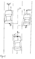
- FIG. 1 a first environment situation is shown as it may occur during the operation of the invention.
- a vehicle 1 which is also referred to as a separate vehicle having an object sensor 2, for example, for an adaptive distance and speed control.
- This own vehicle 1 moves on a road at the speed v, wherein the direction of movement points in the direction of the extended vehicle longitudinal axis 24.
- another vehicle 3 can be seen, which moves in the oncoming traffic lane at the speed v1.
- the object sensor 2 of the vehicle 1 recognizes the vehicle 3 as soon as it enters the object detection area and determines its distance to the own vehicle 1, the relative speed with respect to the own vehicle 1 and the azimuth angle at which the vehicle 3 was detected.
- the object sensor 2 has a coordinate system which has a first coordinate axis in the direction of the extended vehicle longitudinal axis 24 (v coordinate) and a second coordinate axis for q values 4 which indicates the lateral offset.
- the lateral offset q is defined such that positive q-values are defined for left-sided lateral offsets and negative q-values for right-sided lateral offsets.
- the q-axis the other way around, which alters left and right lateral offsets in their sign with respect to the q-values.
- FIG. 1 standing objects 5 shown, which are arranged in the present example objects on the edge of the vehicle. These can be, for example, guide posts, traffic signs, bridge piers, trees, crash barriers or other stationary objects on the roadside.
- the object sensor 2 also detects the objects 5 located on the roadway edge and recognizes from a comparison of the relative speed and the own vehicle speed v that these must be stationary objects. Detects now the object sensor 2 over a long period of time oncoming objects having a negative relative velocity vrel, the amount is greater than the own vehicle speed v and at the same time a left-lateral lateral offset have, it can be concluded from this to a legal transaction.
- the standing objects 5 are evaluated. From the knowledge of the speed v of the own vehicle 1 and the relative speed of the stationary objects 5, which corresponds in magnitude to the own speed of the vehicle 1, stationary objects can be recognized on both sides of the road. For these upright objects 5, the lateral transverse offset q 1, q 2 is calculated, wherein the lateral transverse offset q 1 can only be smaller than a lane width on one side of the extended vehicle longitudinal axis 24.
- standing objects 5 beyond the oncoming lane have a lateral lateral offset q2 with respect to the extended vehicle longitudinal axis 24, which is greater than a lane width.
- the average width of a roadway can be stored in the distance and speed controller as an average value and for example be between 3.4 meters and 3.8 meters.
- FIG. 2 another environment situation is presented, as it can occur especially when driving on multi-lane roads.
- the own vehicle which is equipped with an object sensor 2.
- This own vehicle moves in the present example on the middle lane of a three-lane road.
- another vehicle 6 moves, which is traveling at a speed v2 that is greater than the speed v of the vehicle 1.
- a third vehicle 7 is shown, which is operated at the speed v3, which is smaller than the speed v of the own vehicle 1.
- the vehicle 6 traveling at the speed v2 has recently passed the own vehicle 1, and the third vehicle 7 being moved at the speed v3 lower than the speed v of the own vehicle 1 will shortly become the vehicle own vehicle 1 overhauled.
- the vehicles 6, 7 are located in the object detection area of the object sensor 2, which measures their distance, their relative speed and the azimuth angle of these vehicles. Furthermore, the speed of the own vehicle 1 by the speed sensor 10 is known. From this, the absolute speeds of the vehicles 6, 7 can be calculated, as well as their lateral transverse offset q4, q5 calculated with respect to the extended vehicle longitudinal axis 24. If the object sensor 2 recognizes a vehicle which has a positive relative speed with respect to the vehicle 1, that therefore moves faster than the own vehicle 1, it is closed in the presence of a left-lateral lateral offset q4 on a right-hand traffic and closed at a right-lateral lateral cross-offset on a left-hand traffic.
- a vehicle 7 is detected by the object sensor 2, which has a negative relative speed, wherein the absolute value of the absolute velocity v3 is between zero and the speed v of the own vehicle, this is a slower vehicle, but the same direction of movement own vehicle 1 has.
- a right lateral lateral offset q5 which in the present example can also be a negative q value, is determined with respect to this vehicle 7, the recognition device concludes a right-hand traffic, but the slower vehicle has a left-lateral lateral offset q5 with respect to the extended vehicle longitudinal axis 24 on (positive q value), it is closed to a left-hand traffic.
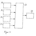
- FIG. 3 a block diagram of an embodiment of the device according to the invention is shown.
- a distance and speed control device 8 which has, inter alia, an input circuit 9.
- the distance and speed controller 8 input signals are supplied.
- These input signals originate, for example, from an object sensor 2, which can be embodied, for example, as a radar, laser, ultrasound, video sensor or a combination thereof, and represent the relative speed, the distance and the azimuth angle of the detected objects with respect to the extended vehicle longitudinal axis 24 the input circuit 9 is supplied with a speed signal from a speed sensor 10, which determines the speed of the own vehicle 1.
- an operating element 11 is provided, by means of which the distance and speed controller 8 can be switched on and off as well as being adjustable and operable.
- the quantities supplied to the input circuit 9 are supplied to a calculation device 13 by means of a data exchange device 12.
- the calculation device 13 is designed for example as a microprocessor or digital signal processor and calculates from the input variables control signals for regulating the vehicle speed and other output variables.
- the method according to the invention is provided, for example in the form of computer software which generates output signals from the input variables in the manner according to the invention.
- the of the Calculation device 13 generated output signals are supplied by means of the data exchange device 12 to an output circuit 14, which outputs, among other control signals to a power-determining actuator of an internal combustion engine 15 and the deceleration device 16 of the vehicle.
- the corresponding power control element 15 which may be, for example, an electrically controllable throttle valve, a fuel quantity metering device of a storage injection system or an electrically controllable control rod of a fuel injection pump, transmits this to a control signal To implement acceleration.
- a deceleration signal is supplied to the deceleration devices 16 of the vehicle.
- This deceleration signal can be converted into a vehicle deceleration, for example, by means of an electrically actuatable brake device, which may be, for example, an electrohydraulic brake or may be an electrically driven servo brake. It is further provided that the output circuit 14 outputs a signal to a display device 17, which tells the driver, which sense of traffic has been detected and is currently set in the distance and speed controller 8.
- the display device 17 may for example be a plain text display in the dashboard of the vehicle or include one or more indicator lights in the dashboard of the vehicle.
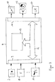
- Function blocks 18 to 21 represent the different detection methods for the sense of traffic. These different recognition methods can run in parallel and pass on their results to a plausibility check stage 22.
- the sense of traffic is determined in block 18, depending on the detected, oncoming, moving targets, as outlined for example by the vehicle 3, the sense of traffic is determined.
- the sense of traffic is determined as a function of the detected, stationary objects, as outlined, for example, by the roadway boundaries 5.
- the sense of traffic determines whether a right or left traffic is present or no result can be determined.
- the detected, movable, slower objects, as they are, for example, in FIG. 2 are sketched by vehicle 7, the current sense of traffic determined.
- the results obtained by the individual recognition methods in blocks 18 to 21 are sent to a plausibility checker 22 and as a result can output either left-hand traffic, right-hand traffic or no detectable result. Because many detection methods work mainly on multi-lane roads and other detection methods mainly operate on lanes that provide oncoming traffic and provide only one lane for each direction of travel, it is possible that not all methods can always give a clear result, and therefore an indeterminate one Condition, so no determinable sense of traffic can be spent.
- the plausibility check 22 checks whether the results which have resulted in either a right-hand traffic or a left-hand traffic are contradictory to one another.
- the results of the detection methods which could determine no result, are not taken into account, the results of a left or right traffic have resulted, but must all have led to a clear result, ie all results that have either left or right traffic must also at the same time have given identical result. If a right-hand traffic or a left-hand traffic is detected by this plausibility checkpoint 22, then this sense of traffic must be stably recognized over a longer period of time, ie no switch to a different sense of traffic during this time must take place. If a sense of traffic is unambiguously detected over the predetermined period of time, then this sense of traffic is transferred in block 23 to the distance and speed controller, which requires this information to set certain driving functions and control parameters.
- the display device 17 which informs the driver of the currently detected sense of traffic output. Furthermore, it can be provided that the driver has the opportunity to intervene manually and set the traffic awareness by a manual specification of the sense of traffic. This possibility ensures that the driver can override the automatic detection in the event of a misrecognized sense of traffic and can give the controller the current, correct sense of traffic.
Description
Die vorliegende Erfindung betrifft ein Vorrichtung und ein Verfahren zur automatischen Erkennung und Einstellung des Verkehrssinns in einer adaptiven Abstands- und Geschwindigkeitsregelung, insbesondere für ein Kraftfahrzeug. Hierzu wird dem adaptiven Abstands- und Geschwindigkeitsregler die Relativgeschwindigkeit detektierter Objekte, der seitliche Versatz der detektierten Objekte bezüglich der Fahrzeuglängsachse und die Geschwindigkeit des eigenen Fahrzeugs zugeführt. In Abhängigkeit der detektierten, entgegenkommenden, beweglichen Objekte, der detektierten, stehenden Objekte, der detektierten, beweglichen, schnelleren Objekte, der detektierten, beweglichen, langsameren Objekte oder einer Kombination hieraus wird entschieden, ob ein Linksverkehr oder ein Rechtsverkehr vorliegt.The present invention relates to an apparatus and a method for the automatic detection and adjustment of the sense of traffic in an adaptive distance and speed control, in particular for a motor vehicle. For this purpose, the adaptive distance and speed controller, the relative speed of detected objects, the lateral offset of the detected objects with respect to the vehicle longitudinal axis and the speed of the own vehicle is supplied. Depending on the detected, oncoming, moving objects, the detected, stationary objects, the detected, moving, faster objects, the detected, mobile, slower objects or a combination thereof, it is decided whether left-hand traffic or right-hand traffic exists.
Aus der Veröffentlichung "Adaptive Cruise Control System - Aspects and Development Trends" von Winner, Witte, Uhler und Lichtenberg, veröffentlicht auf der SAE International Congress & Exposition, 26.-29. Februar 1996 ist ein Abstands- und Geschwindigkeitsregler bekannt, der Radarstrahlung aussendet und die an Objekten reflektierten Teilwellen empfängt. Mittels dem verwendeten FMCW-Modulationsverfahren ist es möglich, aus den empfangenen Radarteilwellen die Relativgeschwindigkeit und den Abstand der erkannten Objekte zu ermitteln und in deren Abhängigkeit die Geschwindigkeit des Fahrzeugs zu regeln. Dabei wird bei einem vorhandenen, vorherfahrenden Fahrzeug eine Geschwindigkeitsregelung im Sinne einer Abstandskonstantregelung durchgeführt und bei Nichtvorhandensein eines vorherfahrenden Fahrzeugs eine Geschwindigkeitsregelung im Sinne einer Konstantgeschwindigkeitsregelung durchgeführt.From the publication "Adaptive Cruise Control System - Aspects and Development Trends" by Winner, Witte, Uhler and Lichtenberg, published at the SAE International Congress & Exposition, 26.-29. February 1996, a distance and velocity controller is known, which emits radar radiation and receives the partial waves reflected on objects. By means of the FMCW modulation method used, it is possible to determine the relative speed and the distance of the detected objects from the received radar sub-waves and to regulate the speed of the vehicle as a function thereof. In the case of an existing, preceding vehicle, a speed control is carried out in the sense of a constant distance control and in the absence of a preceding vehicle carried out a speed control in terms of constant speed control.
Aus der
Aus der
Aus der
Aufgabe der vorliegenden Erfindung ist es, ein Verfahren und eine zugehörige Vorrichtung bereitzustellen, die es erlauben mit hoher Sicherheit den momentan vorherrschenden Verkehrssinn zu erkennen und den Abstands- und Geschwindigkeitsregler dementsprechend einzustellen. Die Kenntnis des Verkehrssinns ist für den Abstands- und Geschwindigkeitsregler von großer Bedeutung, da einzelne Reglerfunktionen die Kenntnis des Verkehrssinns benötigen. Beispielsweise dürfen langsamere Fahrzeuge als das geregelte Fahrzeug nur auf der Seite überholt werden, die für schnelleren Verkehr vorgegeben ist. Dies ist beispielsweise bei rechtssinnigem Verkehr, wie er in Mitteleuropa vorliegt, nur auf der linken Fahrspur möglich, dementsprechend bei Linksverkehr nur auf der rechten Fahrspur erlaubt. Erfindungsgemäß wird dieses durch die Merkmale der unabhängigen Ansprüche gelöst. Vorteilhafte Weiterbildungen und Ausgestaltungen ergeben sich aus den Unteransprüchen.Object of the present invention is to provide a method and an associated device that allow to detect the currently prevailing sense of traffic with high security and adjust the distance and speed controller accordingly. Knowledge of the sense of traffic is of great importance for the distance and speed controller since individual controller functions require knowledge of the sense of traffic. For example, slower vehicles than the regulated vehicle may only be overtaken on the side specified for faster traffic. This is, for example, in rechtssinnigem traffic, as it exists in Central Europe, only on the left lane possible, therefore allowed on left hand traffic only on the right lane. According to the invention this is achieved by the features of the independent claims. Advantageous developments and refinements emerge from the subclaims.
Diese Aufgabe wird durch die Merkmale des Vorrichtungsanspruchs 9 und des Verfahrensanspruchs 1 gelöst.This object is achieved by the features of the
Im Rahmen der vorliegenden Erfindung wird der Begriff "lateraler Querversatz" oder "seitlicher Querversatz" für die kürzeste Entfernung verwendet, die das Objekt zur verlängerten Fahrzeuglängsachse aufweist. Dementsprechend wird auch ein linksseitiger bzw. rechtsseitiger, lateraler Querversatz definiert, wobei ein linksseitiger lateraler Querversatz bedeutet, dass sich das Objekt auf der in Fahrtrichtung des eigenen Fahrzeugs gesehen, linken Halbebene der verlängerten Fahrzeugachse befindet bzw. bei einem rechtsseitigen, lateralen Querversatz sich das Objekt auf der in Fahrtrichtung des eigenen Fahrzeugs gesehenen rechten Halbebene, die durch die verlängerte Fahrzeuglängsachse begrenzt wird, befindet. Wird zusätzlich ein Koordinatensystem bezüglich des am Fahrzeug befestigten Objektsensors definiert, so kann eine erste v-Achse in Fahrtrichtung, also in Richtung der verlängerten Fahrzeuglängsachse vorgesehen sein und eine hierzu rechtwinklige weitere Koordinate, die q-Achse, die den Querversatz definiert. Ist diese beispielsweise derart vorgesehen, dass die positive Richtung der Querversatzkoordinate in Richtung linksseitiger, lateraler Querversätze zeigt und die negative Querveratzkoordinate in Richtung rechtsseitiger, lateraler Querversätze zeigt, so kann man weiterhin die linksseitigen, lateralen Querversätze auch als positive, laterale Querversätze und die rechtsseitigen lateralen Querversätze als negative laterale Querversätze bezeichnen. Weiterhin wird bezüglich der vorliegenden Erfindung von positiven Relativgeschwindigkeiten gesprochen, wenn ein bewegtes Objekt sich in der gleichen Richtung wie das eigene Fahrzeug bewegt jedoch eine größere Absolutgeschwindigkeit als das eigene Fahrzeug aufweist. Dementsprechend werden negative Relativgeschwindigkeiten für Objekte definiert, die sich entweder in der gleichen Bewegungsrichtung wie das eigene Fahrzeug bewegen, jedoch eine geringere Absolutgeschwindigkeit aufweisen oder für Objekte verwendet, die sich in entgegengesetzter Richtung zur eigenen Fahrzeugbewegungsrichtung bewegen und dabei beliebige Geschwindigkeiten aufweisen können.In the context of the present invention, the term "lateral lateral offset" or "lateral lateral offset" is used for the shortest distance that the object has to the extended vehicle longitudinal axis. Accordingly, a left-sided or right-sided, lateral transverse offset is also defined, wherein a left-lateral lateral offset means that the object is on the viewed in the direction of travel of the own vehicle, left half-plane of the elongated vehicle axis or at a right-lateral lateral offset, the object on the seen in the direction of travel of the own vehicle right half-plane, which is bounded by the extended vehicle longitudinal axis is located. If, in addition, a coordinate system is defined with respect to the object sensor fastened to the vehicle, then a first v-axis can be provided in the direction of travel, ie in the direction of the extended vehicle longitudinal axis and a further coordinate which is rectangular thereto, the q-axis, which defines the transverse offset. If this is provided, for example, in such a way that the positive direction of the transverse offset coordinate points in the direction of left-lateral lateral offset and shows the negative lateral offset coordinate in the direction of right lateral lateral offsets, the left lateral lateral offsets can also be referred to as positive lateral lateral offsets and the right lateral lateral offsets Refer to transverse offsets as negative lateral cross offsets. Further, with respect to the present invention, positive relative velocities are used when a moving object moves in the same direction as the own vehicle but has a greater absolute speed than the own vehicle. Accordingly, negative relative velocities are defined for objects that move either in the same direction of travel as their own vehicle, but have a lower absolute velocity, or used for objects that move in the opposite direction of their own vehicle movement direction and can have any speed.
Weiterhin wird im Rahmen der vorliegenden Erfindung der Begriff "Rechtsverkehr" für Verkehrssinne benutzt, bei denen die Verkehrsteilnehmer auf der rechten Seite der Fahrbahn fahren, wie es beispielsweise in Mitteleuropa, den Vereinigten Staaten von Amerika oder den meisten anderen Ländern der Welt vorgesehen ist. Der Begriff "Linksverkehr" wird hingegen für Verkehrssinne verwendet, bei denen die Fahrzeuge auf der linken Seite der Fahrbahn fahren, wie es beispielsweise in Großbritannien, Japan oder Australien der Fall ist.Furthermore, in the context of the present invention, the term "right-hand traffic" is used for traffic senses in which road users drive on the right-hand side of the roadway, as is for example intended in Central Europe, the United States of America or most other countries in the world. The term "left-hand traffic", on the other hand, is used for traffic senses in which the vehicles drive on the left-hand side of the roadway, as is the case for example in the United Kingdom, Japan or Australia.
Vorteilhafterweise wird ein Rechtsverkehr erkannt, wenn die detektierten, entgegenkommenden, bewegten Objekte einen linksseitigen, lateralen Querversatz bezüglich der Fahrzeuglängsachse aufweisen und es wird ein Linksverkehr erkannt, wenn ein rechtsseitiger, lateraler Querversatz erkannt wird.A right-hand traffic is advantageously detected when the detected, oncoming, moving objects have a left-lateral lateral offset with respect to the vehicle longitudinal axis, and a left-hand traffic is detected if a right-lateral lateral offset is detected.
Weiterhin ist es vorteilhaft, dass ein entgegenkommendes, bewegtes Objekt erkannt wird, wenn dieses eine negative Relativgeschwindigkeit aufweist und der Betrag der Relativgeschwindigkeit größer ist als der Betrag der eigenen Fahrzeuggeschwindigkeit.Furthermore, it is advantageous that an oncoming, moving object is detected if it has a negative relative speed and the amount of relative speed is greater than the amount of the vehicle's own speed.
Vorteilhafterweise wird ein Rechtsverkehr erkannt, wenn die detektierten, stehenden Objekte, deren Betrag des lateralen Querversatzes kleiner als eine Fahrspurbreite ist, einen rechtsseitigen, lateralen Querversatz bezüglich der Fahrzeuglängsachse aufweisen und ein Linksverkehr erkannt wird, wenn die detektierten stehenden Objekte, deren Betrag des lateralen Querversatzes kleiner als eine Fahrspurbreite ist, einen rechtsseitigen lateralen Querversatz bezüglich der Fahrzeuglängsachse aufweisen.A right-hand traffic is advantageously detected if the detected, stationary objects whose absolute value of the lateral transverse offset is smaller than a lane width have a right-lateral lateral offset with respect to the vehicle longitudinal axis and a left-hand traffic is detected if the detected stationary objects whose amount of lateral lateral offset is smaller than a lane width, have a right lateral lateral offset with respect to the vehicle longitudinal axis.
Weiterhin ist es vorteilhaft, dass ein stehendes Objekt erkannt wird, wenn der Betrag der Relativgeschwindigkeit in etwa dem Betrag der eigenen Fahrzeuggeschwindigkeit entspricht.Furthermore, it is advantageous that a stationary object is detected when the amount of the relative speed corresponds approximately to the amount of the own vehicle speed.
Vorteilhafterweise wird ein Rechtsverkehr erkannt, wenn die detektierten beweglichen schnelleren Objekte einen linksseitigen, lateralen Querversatz bezüglich der Fahrzeuglängsachse aufweisen und ein Linksverkehr erkannt, wenn die detektierten, beweglichen, schnelleren Objekte einen rechtsseitigen, lateralen Querversatz bezüglich der Fahrzeuglängsachse aufweisen.A right-hand traffic is advantageously detected if the detected mobile faster objects have a left-lateral lateral offset with respect to the vehicle longitudinal axis and a left-hand traffic detected if the detected, movable, faster objects have a right-lateral lateral offset with respect to the vehicle longitudinal axis.
Besonders vorteilhaft ist, dass ein bewegliches, schnelleres Objekt erkannt wird, wenn die Relativgeschwindigkeit bezüglich des eigenen Fahrzeugs positiv ist.It is particularly advantageous that a movable, faster object is detected when the relative speed with respect to the own vehicle is positive.
Vorteilhafterweise wird ein Rechtsverkehr erkannt, wenn die detektierten, beweglichen, langsameren Objekte einen rechtsseitigen lateralen Querversatz bezüglich der Fahrzeuglängsachse aufweisen und ein Linksverkehr erkannt, wenn die detektierten, beweglichen, langsameren Objekte einen linksseitigen, lateralen Querversatz bezüglich der Fahrzeuglängsachse aufweisen.A right-hand traffic is advantageously detected when the detected, movable, slower objects have a right-lateral lateral offset with respect to the vehicle longitudinal axis and a left-hand traffic recognized when the detected, movable, slower objects have a left-lateral lateral offset with respect to the vehicle longitudinal axis.
Besonders vorteilhaft ist, dass ein bewegliches, langsameres Objekt erkannt wird, wenn die Relativgeschwindigkeit bezüglich des eigenen Fahrzeugs negativ ist und der Betrag der Relativgeschwindigkeit zwischen Null und dem Betrag der eigenen Fahrzeuggeschwindigkeit liegt.It is particularly advantageous that a movable, slower object is detected when the relative speed with respect to the own vehicle is negative and the amount of the relative speed is between zero and the amount of the own vehicle speed.
Vorteilhafterweise werden die Erkennungsverfahren für Rechts- und Linksverkehr gegenseitig auf Plausibilität überprüft. Als Erkennungsverfahren im Rahmen der vorliegenden Erfindung wird zum einen die Verkehrssinnerkennung anhand der detektierten, entgegenkommenden, beweglichen Ziele betrachtet, die Erkennung des Verkehrssinns mittels der detektierten, stehenden Objekte, die Erkennung des Verkehrssinns mittels der detektierten, beweglichen, schnelleren Objekte sowie die Verkehrssinnerkennung mittels der detektierten, beweglichen, langsameren Objekte betrachtet. Jedes dieser Erkennungsverfahren kann als Ergebnis Links- oder Rechtsverkehr oder keine Aussage ergeben. So ist beispielsweise die Detektion von beweglichen, schnelleren oder langsameren Objekten auf benachbarten Fahrspuren nur auf mehrspurigen Strassen möglich, wobei bei mehrspurigen Strassen die Detektion entgegenkommender, beweglicher Ziele unmöglich sein kann. Gleichzeitig kann bei der Detektion von entgegenkommenden, beweglichen Zielen eine Detektion von beweglichen, schnelleren oder langsameren Objekten unmöglich sein. So ist es möglich, dass im Rahmen der Plausibilitätsprüfung nicht zwangsweise alle Einzelverfahren zu dem gleichen Ergebnis kommen können, sondern einzelne Verfahren auch zu keinem Ergebnis führen können. Es ist jedoch im Rahmen der Plausibilitätsprüfung notwendig, dass die Ergebnisse von Erkennungsverfahren, die einen links- oder rechtssinnigen Verkehrssinn erkannt haben, gegenseitig zu vergleichen, wobei alle Erkennungsverfahren, die einen Verkehrssinn erkannt haben übereinstimmen müssen, um Fehlerkennungen der Einzelsysteme möglichst gering zu halten. Weiterhin kann im Rahmen der Plausibilitätsüberprüfung eine zeitliche Mittelung erfolgen, so dass bei einer kurzfristigen Erkennung eines anderen Verkehrssinns nicht sofort diese dem Fahrer mitgeteilt wird und die adaptive Abstands- und Geschwindigkeitsregelung entsprechend umgestellt wird, sondern dass dieser neue erkannte Verkehrssinn für eine vorbestimmte Zeitdauer sicher erkannt werden muss, bevor eine Umstellung des adaptiven Abstands- und Geschwindigkeitsreglers sowie die Anzeige des neuen Verkehrssinns erfolgt. Dies führt dazu, dass kurzfristige Störungen die zu einer Umschaltung der Verkehrssinnerkennung führen können, vermieden werden und erst bei einer sicheren Erkennung dieses neuen Verkehrssinns dieses weitergeleitet und weiterverarbeitet wird.Advantageously, the detection methods for right and left traffic are mutually checked for plausibility. As a recognition method in the context of the present invention, on the one hand, the traffic awareness is based on the Viewing detected, oncoming, moving targets, the detection of the sense of traffic by means of the detected, stationary objects, the detection of the sense of traffic by means of the detected, mobile, faster objects and the traffic awareness by means of the detected, moving, slower objects considered. Each of these recognition methods can result in left or right-hand traffic or no statement. Thus, for example, the detection of moving, faster or slower objects on adjacent lanes is only possible on multi-lane roads, with multi-lane roads, the detection of oncoming, moving targets may be impossible. At the same time, the detection of oncoming, moving targets may make it impossible to detect moving, faster or slower objects. It is thus possible that in the context of the plausibility check not all individual procedures can come to the same result, but that individual procedures can not lead to any result. However, it is necessary in the context of the plausibility check that the results of detection methods that have detected a left- or right-wing sense of traffic, to compare each other, all detection methods that have detected a sense of traffic must match to minimize detection errors of the individual systems. Furthermore, in the context of the plausibility check, a time averaging done so that in a short-term detection of another sense of traffic is not immediately informed to the driver and the adaptive distance and speed control is changed accordingly, but that this new detected sense of traffic for a predetermined period of time safely detected must be before a changeover of the adaptive distance and speed controller and the display of the new sense of traffic takes place. This means that short-term disturbances that can lead to a switching of the traffic awareness, can be avoided and only with a secure detection of this new sense of traffic, this is forwarded and further processed.
Weiterhin ist es vorteilhaft, dass der momentan erkannte Verkehrssinn dem Fahrer mittels einer Anzeigevorrichtung angezeigt wird. Dies kann beispielsweise durch das Aufleuchten einer Kontrolllampe oder mittels einer Klartextanzeige oder einer symbolischen Anzeige in einem Display des Armaturenbrettes angezeigt werden.Furthermore, it is advantageous that the currently detected sense of traffic is displayed to the driver by means of a display device. This can be indicated for example by the illumination of a control lamp or by means of a plain text display or a symbolic display in a display of the dashboard.
Weiterhin ist es vorteilhaft, dass das Mittel zur Bestimmung des Abstandes, der Relativgeschwindigkeit detektierter Objekte und des azimutalen Objektwinkels, unter dem das Objekt detektiert wurde, aus dem der seitlichen Versatzes der detektierten Objekte bezüglich der Fahrzeuglängsachse ermittelbar ist, ein Radarsensor, ein Lasersensor, ein Ultraschallsensor, ein Videosensor oder eine Kombination hieraus ist.Furthermore, it is advantageous that the means for determining the distance, the relative velocity of detected objects and the azimuthal object angle, under the object has been detected, from which the lateral offset of the detected objects with respect to the vehicle longitudinal axis can be determined, a radar sensor, a laser sensor, an ultrasonic sensor, a video sensor or a combination thereof.
Von besonderer Bedeutung ist die Realisierung des erfindungsgemäßen Verfahrens in der Form eines Steuerelements, das für ein Steuergerät einer adaptiven Abstands- bzw. Geschwindigkeitsregelung eines Kraftfahrzeugs vorgesehen ist. Dabei ist auf dem Steuerelement ein Programm gespeichert, das auf einem Rechengerät, insbesondere auf einem Mikroprozessor oder Signalprozessor ablauffähig und zur Ausführung des erfindungsgemäßen Verfahrens geeignet ist. In diesem Fall wird also die Erfindung durch ein auf dem Steuerelement abgespeichertes Programm realisiert, so dass dieses mit dem Programm versehene Steuerelement in gleicher Weise die Erfindung darstellt, wie das Verfahren, zu dessen Ausführung das Programm geeignet ist. Als Steuerelement kann insbesondere ein elektrisches Speichermedium zur Anwendung kommen, beispielsweise ein Read-Only-Memory.Of particular importance is the realization of the method according to the invention in the form of a control element which is provided for a control unit of an adaptive distance or speed control of a motor vehicle. In this case, a program is stored on the control, which is executable on a computing device, in particular on a microprocessor or signal processor and suitable for carrying out the method according to the invention. In this case, therefore, the invention is realized by a program stored on the control program, so that this provided with the program control in the same way represents the invention, as the method to whose execution the program is suitable. In particular, an electrical storage medium can be used as the control, for example a read-only memory.
Nachfolgend werden Ausführungsbeispiele der Erfindung anhand von Zeichnungen erläutert. Es zeigen
Figur 1- eine erste Umfeldsituation, wie sie während dem erfindungsgemäßen Betrieb vorkommen kann,
Figur 2- eine zweite Umfeldsituation, wie sie während dem erfindungsgemäßen Betrieb vorkommen kann,
Figur 3- ein schematisches Blockdiagramm einer Ausführungsform der erfindungsgemäßen Vorrichtung und
Figur 4- ein schematisches Blockdiagramm einer Ausführungsform des erfindungsgemäßen Verfahrens.
- FIG. 1
- a first environment situation, as may occur during the operation according to the invention,
- FIG. 2
- a second environment situation, as may occur during the operation according to the invention,
- FIG. 3
- a schematic block diagram of an embodiment of the device according to the invention and
- FIG. 4
- a schematic block diagram of an embodiment of the method according to the invention.
In
In
In
In
Claims (10)
- Method for automatically detecting and setting right-hand driving or left-hand driving in an adaptive inter-vehicle distance and cruise controller (8), in particular for a motor vehicle (1), wherein the relative velocity of detected objects (3, 5, 6, 7), the lateral offset (q1, q2, q3, q4, q5) of the detected objects (3, 5, 6, 7) with respect to the longitudinal axis (24) of the vehicle and the velocity (v) of the driver's own vehicle (1) are fed to the adaptive inter-vehicle distance and cruise controller (8), wherein- as a function of the detected, oncoming moving targets (3, 18) it is decided whether left-hand driving or right-hand driving is present in that right-hand driving is detected if the detected, oncoming moving objects (3) have a left-sided lateral offset (q3) with respect to the longitudinal axis (24) of the vehicle, and left-hand driving is detected if a right-sided lateral offset (q3) is detected, and- as a function of the detected stationary objects (5, 19) it is decided whether left-hand driving or right-hand driving is present in that right-hand driving is detected if the detected stationary objects (5) whose amount of lateral offset (q1, q2) is less than a lane width have a right-sided lateral offset (q1, q2) with respect to the longitudinal axis (24) of the vehicle, and left-hand driving is detected if the detected stationary objects (5) whose amount of lateral offset (q1, q2) is less than a lane width have a left-sided lateral offset (q1, q2) with respect to the longitudinal axis (24) of the vehicle,characterized in that the detection methods for right-hand and left-hand driving are checked against one another for plausibility (22), and a detected change in the right-hand or left-hand driving for a predetermined time period has to be reliably detected before the adaptive inter-vehicle distance and cruise controller is reset and the new right-hand or left-hand driving is displayed.
- Method according to Claim 1, characterized in that an oncoming moving object (3) is detected if it has a negative relative velocity and the absolute value of the relative velocity is higher than the absolute value of the velocity (v) of the driver's own vehicle.
- Method according to Claim 1, characterized in that a stationary object is detected if the absolute value of the relative velocity corresponds approximately to the absolute value of the velocity (v) of the driver's own vehicle.
- Method according to Claim 1, characterized in that right-hand driving is detected if the detected moving relatively fast objects (6) have a left-sided lateral offset (q4) with respect to the longitudinal axis (24) of the vehicle, and left-hand driving is detected if the detected moving relatively fast objects (6) have a right-sided lateral offset (q4) with respect to the longitudinal axis of the vehicle.
- Method according to Claim 1 or 4, characterized in that a moving relatively fast object (6) is detected if the relative velocity is positive with respect to the driver's own vehicle (1).
- Method according to Claim 1, characterized in that right-hand driving is detected if the detected moving relatively slow objects (7) have a right-sided lateral offset (q5) with respect to the longitudinal axis (24) of the vehicle, and left-hand driving is detected if the detected moving relatively slow objects (7) have a left-sided lateral offset (q5) with respect to the longitudinal axis (24) of the vehicle.
- Method according to Claim 1 or 6, characterized in that a moving relatively slow object (7) is detected if the relative velocity is negative with respect to the driver's own vehicle (1) and the absolute value of the relative velocity is between zero and the absolute value of the velocity (v) of the driver's own vehicle.
- Method according to Claim 1, characterized in that the instantaneously detected right-hand driving or left-hand driving is displayed (23) to the driver by means of a display device (17).
- Device for automatically detecting and setting right-hand driving or left-hand driving in an adaptive inter-vehicle distance and cruise controller (8), in particular for a motor vehicle (1), wherein means (2, 10) are provided for determining the relative velocity of detected objects, the lateral offset of the detected objects with respect to the longitudinal axis of the vehicle and the velocity of the driver's own vehicle, characterized in that the method according to Claim 1 runs in the device.
- Device according to Claim 9, characterized in that the means (2) for determining the relative velocity of detected objects and the lateral offset of the detected objects with respect to the longitudinal axis (24) of the vehicle is a radar sensor, a laser sensor, an ultrasonic sensor, a video sensor or a combination thereof.
Applications Claiming Priority (2)
| Application Number | Priority Date | Filing Date | Title |
|---|---|---|---|
| DE10345809A DE10345809A1 (en) | 2003-09-30 | 2003-09-30 | Method and device for detecting and adjusting the sense of traffic |
| DE10345809 | 2003-09-30 |
Publications (3)
| Publication Number | Publication Date |
|---|---|
| EP1520745A2 EP1520745A2 (en) | 2005-04-06 |
| EP1520745A3 EP1520745A3 (en) | 2005-09-07 |
| EP1520745B1 true EP1520745B1 (en) | 2009-03-04 |
Family
ID=34306205
Family Applications (1)
| Application Number | Title | Priority Date | Filing Date |
|---|---|---|---|
| EP04022036A Active EP1520745B1 (en) | 2003-09-30 | 2004-09-16 | Method and device for Recognising and adjusting left-hand or right hand driving |
Country Status (3)
| Country | Link |
|---|---|
| EP (1) | EP1520745B1 (en) |
| JP (1) | JP4723220B2 (en) |
| DE (2) | DE10345809A1 (en) |
Families Citing this family (15)
| Publication number | Priority date | Publication date | Assignee | Title |
|---|---|---|---|---|
| JP4955246B2 (en) * | 2005-09-29 | 2012-06-20 | アルパイン株式会社 | Car navigation system |
| JP4426535B2 (en) | 2006-01-17 | 2010-03-03 | 本田技研工業株式会社 | Vehicle periphery monitoring device |
| US7518545B2 (en) * | 2006-10-26 | 2009-04-14 | Infineon Technologies Ag | Driver assistance system |
| DE102007059083A1 (en) * | 2006-12-19 | 2008-06-26 | Adc Automotive Distance Control Systems Gmbh | Control system reversible adjustment equipment for e.g. passenger car, has device provided for adjusting control system in dependent of determination whether motor vehicle is operated in left hand driving or in right hand driving |
| GB2498223B (en) * | 2012-01-09 | 2015-08-26 | Jaguar Land Rover Ltd | Method and control unit for monitoring traffic |
| US8504233B1 (en) * | 2012-04-27 | 2013-08-06 | Google Inc. | Safely navigating on roads through maintaining safe distance from other vehicles |
| SE536656C2 (en) | 2012-09-17 | 2014-05-06 | Scania Cv Ab | Device and method for automatically determining whether a vehicle is propelled in left or right-hand traffic |
| DE102015226840A1 (en) * | 2015-11-03 | 2017-05-04 | Robert Bosch Gmbh | Method for operating a longitudinal control device of a motor vehicle in a roundabout |
| DE102016009762A1 (en) * | 2016-08-11 | 2018-02-15 | Trw Automotive Gmbh | Control system and control method for determining a likelihood of a lane change of a preceding motor vehicle |
| CN106585622A (en) * | 2016-12-20 | 2017-04-26 | 奇瑞汽车股份有限公司 | Method for driving automatically under road construction condition and smart car |
| KR102581766B1 (en) * | 2018-10-08 | 2023-09-22 | 주식회사 에이치엘클레무브 | Vehicle control apparatus and vehicle control method and vehicle control system |
| CN112835008B (en) * | 2021-01-12 | 2022-03-04 | 西安电子科技大学 | High-resolution range profile target identification method based on attitude self-adaptive convolutional network |
| JP2022175973A (en) * | 2021-05-14 | 2022-11-25 | 株式会社デンソー | Vehicle control device and vehicle control system |
| DE102022201200A1 (en) | 2022-02-04 | 2023-08-10 | Continental Autonomous Mobility Germany GmbH | Method and system for determining traffic orientation |
| DE102022203280A1 (en) | 2022-04-01 | 2023-10-05 | Continental Autonomous Mobility Germany GmbH | Method and system for determining a lane direction |
Family Cites Families (5)
| Publication number | Priority date | Publication date | Assignee | Title |
|---|---|---|---|---|
| JP3160108B2 (en) * | 1993-02-23 | 2001-04-23 | 三菱電機株式会社 | Driving support system |
| JP3470453B2 (en) * | 1995-04-06 | 2003-11-25 | 株式会社デンソー | Inter-vehicle distance control device |
| DE19637053C2 (en) * | 1996-09-12 | 2000-03-09 | Bosch Gmbh Robert | Method and device for automatic detection of right-hand or left-hand traffic |
| DE19828160B4 (en) * | 1998-06-24 | 2008-02-14 | Volkswagen Ag | Method for automatic recognition of the main roadway in a multi-lane route |
| DE10254423A1 (en) * | 2002-11-21 | 2004-06-03 | Lucas Automotive Gmbh | System for influencing the speed of a motor vehicle |
-
2003
- 2003-09-30 DE DE10345809A patent/DE10345809A1/en not_active Withdrawn
-
2004
- 2004-09-16 DE DE502004009069T patent/DE502004009069D1/en active Active
- 2004-09-16 EP EP04022036A patent/EP1520745B1/en active Active
- 2004-09-29 JP JP2004283749A patent/JP4723220B2/en active Active
Also Published As
| Publication number | Publication date |
|---|---|
| JP4723220B2 (en) | 2011-07-13 |
| DE502004009069D1 (en) | 2009-04-16 |
| JP2005104462A (en) | 2005-04-21 |
| DE10345809A1 (en) | 2005-04-21 |
| EP1520745A3 (en) | 2005-09-07 |
| EP1520745A2 (en) | 2005-04-06 |
Similar Documents
| Publication | Publication Date | Title |
|---|---|---|
| EP1671196B1 (en) | Method and device for lane recognition for a vehicle | |
| EP1292462B1 (en) | Method and system for controlling the distance of a first vehicle in relation to a preceding vehicle | |
| EP1940665B1 (en) | Adaptive cruise control featuring recognition of a traffic jam | |
| DE10015300B4 (en) | Method and device for controlling the driving speed of a vehicle | |
| EP1520745B1 (en) | Method and device for Recognising and adjusting left-hand or right hand driving | |
| EP1777143B1 (en) | Lane-change assistant | |
| EP1577682B1 (en) | Object locating system for vehicles to recognize lane change | |
| EP1625979B1 (en) | Method and device for triggering an emergency braking | |
| DE10358034A1 (en) | Adaptation of an automatic follow-up to potential road users shunting their own lane | |
| DE102012204441A1 (en) | Method and device for detecting a course of a road for vehicles | |
| DE10254424A1 (en) | System for influencing the speed of a motor vehicle | |
| WO2009068128A1 (en) | Method for distance regulation for a vehicle and distance regulation system for performing the method | |
| DE102005046841A1 (en) | Method for composition of state vector with object attribute value of target object for submission in vehicle control system involves formation of several state vectors by objects, which are possibly relevant for vehicle control | |
| DE102011083265A1 (en) | Method for detecting presence of structural separation between two roads, using driver assistance device, involves determining lateral distance of light object with respect to travel direction of vehicle, with camera mounted in vehicle | |
| EP1562774A1 (en) | System for influencing the speed of a motor vehicle | |
| EP3639053A1 (en) | Sensor apparatus for an automated vehicle | |
| EP2181891A2 (en) | Method and device for adjusting curve lighting headlights, particularly when driving through crossroads or confluences | |
| DE19828160B4 (en) | Method for automatic recognition of the main roadway in a multi-lane route | |
| EP1900586A2 (en) | Device for distance control with target object display | |
| EP1529719B1 (en) | Vehicle guidance apparatus with lateral guiding and object recognition and corresponding method | |
| EP1562781A1 (en) | System for recognising left-hand or right-hand driving conditions | |
| DE102010056248A1 (en) | Method for controlling sequence distance of vehicle moving on lane to another vehicle moving on same lane before former vehicle, involves determining whether third vehicle moves on lane in driving direction of vehicle | |
| DE102022119571A1 (en) | Notification control device for a vehicle | |
| EP0889456B1 (en) | Method to control an automatic distance regulation system for a vehicle | |
| DE10250679A1 (en) | Method and device for regulating the speed of a vehicle |
Legal Events
| Date | Code | Title | Description |
|---|---|---|---|
| PUAI | Public reference made under article 153(3) epc to a published international application that has entered the european phase |
Free format text: ORIGINAL CODE: 0009012 |
|
| AK | Designated contracting states |
Kind code of ref document: A2 Designated state(s): AT BE BG CH CY CZ DE DK EE ES FI FR GB GR HU IE IT LI LU MC NL PL PT RO SE SI SK TR |
|
| AX | Request for extension of the european patent |
Extension state: AL HR LT LV MK |
|
| PUAL | Search report despatched |
Free format text: ORIGINAL CODE: 0009013 |
|
| AK | Designated contracting states |
Kind code of ref document: A3 Designated state(s): AT BE BG CH CY CZ DE DK EE ES FI FR GB GR HU IE IT LI LU MC NL PL PT RO SE SI SK TR |
|
| AX | Request for extension of the european patent |
Extension state: AL HR LT LV MK |
|
| RIC1 | Information provided on ipc code assigned before grant |
Ipc: 7B 60K 31/00 A Ipc: 7G 01S 13/93 B |
|
| 17P | Request for examination filed |
Effective date: 20060307 |
|
| AKX | Designation fees paid |
Designated state(s): DE FR GB SE |
|
| GRAP | Despatch of communication of intention to grant a patent |
Free format text: ORIGINAL CODE: EPIDOSNIGR1 |
|
| GRAS | Grant fee paid |
Free format text: ORIGINAL CODE: EPIDOSNIGR3 |
|
| GRAA | (expected) grant |
Free format text: ORIGINAL CODE: 0009210 |
|
| AK | Designated contracting states |
Kind code of ref document: B1 Designated state(s): DE FR GB SE |
|
| REG | Reference to a national code |
Ref country code: GB Ref legal event code: FG4D Free format text: NOT ENGLISH |
|
| REF | Corresponds to: |
Ref document number: 502004009069 Country of ref document: DE Date of ref document: 20090416 Kind code of ref document: P |
|
| PG25 | Lapsed in a contracting state [announced via postgrant information from national office to epo] |
Ref country code: SE Free format text: LAPSE BECAUSE OF FAILURE TO SUBMIT A TRANSLATION OF THE DESCRIPTION OR TO PAY THE FEE WITHIN THE PRESCRIBED TIME-LIMIT Effective date: 20090604 |
|
| PLBE | No opposition filed within time limit |
Free format text: ORIGINAL CODE: 0009261 |
|
| STAA | Information on the status of an ep patent application or granted ep patent |
Free format text: STATUS: NO OPPOSITION FILED WITHIN TIME LIMIT |
|
| 26N | No opposition filed |
Effective date: 20091207 |
|
| REG | Reference to a national code |
Ref country code: FR Ref legal event code: PLFP Year of fee payment: 13 |
|
| REG | Reference to a national code |
Ref country code: FR Ref legal event code: PLFP Year of fee payment: 14 |
|
| REG | Reference to a national code |
Ref country code: FR Ref legal event code: PLFP Year of fee payment: 15 |
|
| PGFP | Annual fee paid to national office [announced via postgrant information from national office to epo] |
Ref country code: GB Payment date: 20200923 Year of fee payment: 17 Ref country code: FR Payment date: 20200921 Year of fee payment: 17 |
|
| GBPC | Gb: european patent ceased through non-payment of renewal fee |
Effective date: 20210916 |
|
| PG25 | Lapsed in a contracting state [announced via postgrant information from national office to epo] |
Ref country code: GB Free format text: LAPSE BECAUSE OF NON-PAYMENT OF DUE FEES Effective date: 20210916 Ref country code: FR Free format text: LAPSE BECAUSE OF NON-PAYMENT OF DUE FEES Effective date: 20210930 |
|
| PGFP | Annual fee paid to national office [announced via postgrant information from national office to epo] |
Ref country code: DE Payment date: 20231124 Year of fee payment: 20 |