EP1520354B1 - Selective power control messaging - Google Patents
Selective power control messaging Download PDFInfo
- Publication number
- EP1520354B1 EP1520354B1 EP03742421A EP03742421A EP1520354B1 EP 1520354 B1 EP1520354 B1 EP 1520354B1 EP 03742421 A EP03742421 A EP 03742421A EP 03742421 A EP03742421 A EP 03742421A EP 1520354 B1 EP1520354 B1 EP 1520354B1
- Authority
- EP
- European Patent Office
- Prior art keywords
- power control
- control message
- signal
- message
- quality
- Prior art date
- Legal status (The legal status is an assumption and is not a legal conclusion. Google has not performed a legal analysis and makes no representation as to the accuracy of the status listed.)
- Expired - Lifetime
Links
- 230000005540 biological transmission Effects 0.000 claims abstract description 93
- 238000000034 method Methods 0.000 claims abstract description 28
- 238000012986 modification Methods 0.000 claims abstract description 18
- 230000004048 modification Effects 0.000 claims abstract description 18
- 238000004891 communication Methods 0.000 claims description 42
- 230000007423 decrease Effects 0.000 claims description 26
- 230000004044 response Effects 0.000 claims description 6
- 238000012545 processing Methods 0.000 description 11
- 238000005259 measurement Methods 0.000 description 6
- 238000010586 diagram Methods 0.000 description 5
- 230000006870 function Effects 0.000 description 5
- 230000008569 process Effects 0.000 description 5
- 230000001413 cellular effect Effects 0.000 description 4
- 230000008859 change Effects 0.000 description 3
- 230000003044 adaptive effect Effects 0.000 description 2
- 238000004590 computer program Methods 0.000 description 2
- 238000005516 engineering process Methods 0.000 description 2
- 238000001914 filtration Methods 0.000 description 2
- 238000010295 mobile communication Methods 0.000 description 2
- 230000003287 optical effect Effects 0.000 description 2
- 230000006978 adaptation Effects 0.000 description 1
- 238000003491 array Methods 0.000 description 1
- 230000003190 augmentative effect Effects 0.000 description 1
- 230000006399 behavior Effects 0.000 description 1
- 238000012508 change request Methods 0.000 description 1
- 238000007796 conventional method Methods 0.000 description 1
- 238000012937 correction Methods 0.000 description 1
- 230000003247 decreasing effect Effects 0.000 description 1
- 229920005994 diacetyl cellulose Polymers 0.000 description 1
- 235000019800 disodium phosphate Nutrition 0.000 description 1
- 230000000694 effects Effects 0.000 description 1
- 238000012544 monitoring process Methods 0.000 description 1
- 230000005855 radiation Effects 0.000 description 1
- 230000009467 reduction Effects 0.000 description 1
- 238000011160 research Methods 0.000 description 1
- 230000011664 signaling Effects 0.000 description 1
- 230000001629 suppression Effects 0.000 description 1
Images


Classifications
-
- H—ELECTRICITY
- H04—ELECTRIC COMMUNICATION TECHNIQUE
- H04W—WIRELESS COMMUNICATION NETWORKS
- H04W52/00—Power management, e.g. Transmission Power Control [TPC] or power classes
- H04W52/04—Transmission power control [TPC]
- H04W52/54—Signalisation aspects of the TPC commands, e.g. frame structure
- H04W52/58—Format of the TPC bits
-
- H—ELECTRICITY
- H04—ELECTRIC COMMUNICATION TECHNIQUE
- H04W—WIRELESS COMMUNICATION NETWORKS
- H04W52/00—Power management, e.g. Transmission Power Control [TPC] or power classes
- H04W52/04—Transmission power control [TPC]
- H04W52/30—Transmission power control [TPC] using constraints in the total amount of available transmission power
- H04W52/36—Transmission power control [TPC] using constraints in the total amount of available transmission power with a discrete range or set of values, e.g. step size, ramping or offsets
Definitions
- the invention relates generally to the field of wireless communications. More particularly, the invention relates to selective power control messaging.
- Certain conventional methods are known for controlling transmission power.
- a "closed-loop" method In one conventional variant of closed-loop transmission power control, the receiving end of a communications link monitors the quality of communications. If the communications quality falls below a certain reference value, a message is transmitted via a return communications path requesting an increase in the transmission power. If instead the communications quality exceeds a certain reference value, then a message is transmitted via the return communications path requesting a decrease in the transmission power.
- power control messages are communications overhead, and any data bits that are devoted to power control are unavailable for communications. For this reason, the size of power control messages may be reduced, but at the cost of reducing flexibility.
- the smallest power control message that may be sent in one transmission is a one-bit message.
- the message requests either an increase or decrease in transmission power by some fixed amount. If the fixed amount is relatively small, a one-bit message may not allow for power modifications quickly enough. If the fixed amount is relatively large, the power modifications may not provide for modifications that are sufficiently fine to accurately control transmission power.
- a conventional system may allow for flexibility in power adjustment, but with a relatively large loss in communications, or may cause a minimal effect on communications, but with little flexibility in transmission power control.
- UK Patent Application No. GB 2341294A of Roke Manor Research Limited, entitled “Enhanced Power Control Signaling in a CDMA Cellular Radio System”, regards a cellular mobile radio system in which, in circumstances in which frames need to be divided, a divided frame includes a greater number of transmission power control (TPC) bits than normally present, the additional TPC bits being transmitted in place of transmission format indicator (TFI) bits that are eliminated from the divided frame.
- TPC transmission power control
- US Patent No. 6,075,974 of Saints, et al. entitled “Method and Apparatus for Adjusting Thresholds and Measurements of Received Signals by Anticipating Power Control Commands Yet to be Executed”, regards a mobile station or receiver to adjust forward link quality or power level thresholds that it compares with incoming frames or portions thereof to reflect a level the station or receiver anticipates receiving after a delay based on a number of previously transmitted messages to a base station.
- a power control processor may provide more than a single bit per window or frame in each power control message providing varying power increases or decreases.
- a method comprising receiving a first wireless signal at a first radio unit, the first wireless signal being received from a second radio unit; determining a quality of the received first signal, including comparing the quality of the first signal to a reference signal quality; and transmitting a second wireless message including a power control message from the first radio unit to the second radio unit, the power control message being of a selected size, the power control message being transmitted to request a modification in transmission power, the power control message being based at least in part on the quality of the received first signal, the power control message comprising: a basic power message, the basic power message comprising one of a request to increase transmission power by a predetermined amount or a request to decrease transmission power by a predetermined amount, the basic power message being included in a header of the second wireless message transmitted by the first radio unit, and an optional extended power control message, the extended power control message comprising a request to increase or decrease transmission power by an amount specified by the extended power control message, the extended power control message being included in
- a radio unit comprising a receiver to receive a first signal from a second radio unit, the radio unit determining a quality of the first signal including comparing the quality of the first signal to a reference signal quality; and a transmitter to transmit a second signal to the second radio unit, the second signal including a power control message to request a modification in transmission power, the power control message being of a selected size, the power control message being based at least in part on the quality of the first signal, the power control message comprising: a basic power message, the basic power message comprising one of a request to increase transmission power by a predetermined amount or a request to decrease transmission power by a predetermined amount, the basic power message being included in a header of the second signal transmitted by the first radio unit, and an optional extended power control message, the extended power control message comprising a request to increase or decrease transmission power by an amount specified by the extended power control message, the extended power control message being included in a data payload of the second signal, wherein a determination whether
- a carrier medium carrying computer readable code for controlling a computer to carry out the aforementioned method.
- Figure 4 is a flow diagram illustrating a process for transmission power control under an embodiment of the invention.
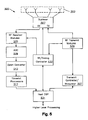
- FIG. 5 is a simplified block diagram illustrating a base station on which an embodiment of the invention can be implemented.
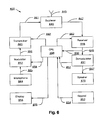
- Figure 6 is a simplified block diagram illustrating a remote terminal on which an embodiment of the invention can be implemented.
- An embodiment of the present invention provides for control of communications transmission power using a power control message of a selectable size, allowing for flexible power control while minimizing the amount of data that is required to transmit the control message.
- a first radio transceiver transmits a signal to a second radio transceiver. Based at least in part on the quality of the received signal, the second radio transceiver transmits a message to the first radio transceiver, the message including a power control message requesting modification of the transmission power of the first radio transceiver.
- the power control message is of a size selected by the second radio transceiver based on the circumstances. Under one embodiment, the power control message includes a first portion and optionally includes an additional second portion, the second portion being included when the first portion isn't sufficient.
- the first radio transceiver adjusts its transmission power in response to the request.
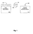
- Figure 1 is a simplified illustration of transmissions between a first device and a second device under an embodiment of the invention.
- the first device is shown as a base station 105 including multiple antennas.
- the second device is shown as a remote terminal 115 with a single antenna.
- the present invention may be implemented with the devices swapped, the remote terminal being the first device transmitting the first signal and the base station being the second device receiving the first signal.
- the base station 105 transmits a first signal 125 to the remote terminal 115.
- the remote terminal evaluates a quality of the first signal 125. In one embodiment of the invention, the quality of the first signal is compared to a reference signal quality.
- the remote terminal transmits a second signal 130 to the base station 105.
- the second signal 130 includes a power control message of a selected size.
- the power control message includes a basic power control message and an optional extended power control message.
- a power control message of selectable size may be constructed in different forms or may include additional elements.
- a power control message includes a first power control message and an optional second power control message.
- the first power control message is a basic power control message.
- the basic power control message is present in each power control message.
- the basic power control message is a request to increase the transmission power by a particular amount or to decrease the transmission power by a particular amount.
- the second power control message is an extended power control message.
- the extended power control message is included in a power control message when the basic power control message is not sufficient.
- the extended power control message is a request to modify the transmission power by an amount specified by the extended power control message.
- the basic power control message requires a single bit of data.
- the two possible values of the basic power control message indicate a request to either increase the transmission power by a predetermined amount or decrease the transmission power by a predetermined amount.
- the basic power control message requests that transmission power be increased or decreased by one decibel, but in other embodiments the predetermined amount may vary, or the predetermined increase amount may be different than the predetermined decrease amount.
- the extended power control message requires a plurality of bits of data and is a request to modify transmission power by an amount specified by the extended power control message.
- the extended power control message uses five bits of data, but the size of the message may be different in other embodiments, or may be of varying size.
- the basic power control message is ignored if a power control message also includes an extended power control message.
- the basic power control signal may not be ignored in such circumstances, and, for example, may be included as part of the extended power control message, or may be used for other purposes in the power control message.
- a basic power control message is included in a header of a message.
- a header includes a fixed number of bits, one of which is the basic power control message.
- an extended power control message is included in a data payload of a message. Because the extended power control message is only included when needed, the communications data that is used for requesting a transmission power change is minimized.
- the basic power control message is sufficient, only a small amount of information in the message header is needed to communicate the power control message.
- the power control message includes the extended power control message in the data payload. The inclusion of the extended power control message in the data payload of a message reduces the amount of space available for communications data transmission, but such reduction in space is only necessary when the extended power control message is needed.
- FIG 2 is an illustration of a data transmission 200 under an embodiment of the invention.
- the data transmission 200 in Figure 2 contains a power control message that is of a selected size.
- the power control message includes a basic power control message and an optional extended power control message.
- the power control message may be in many different forms and the possible selected sizes of the power control message may vary greatly.
- the data transmission 200 includes a header 205 and a data payload 210.
- the header includes twenty-eight bits of data.
- the header 205 includes a basic power control message 215, the basic power control message requesting an increase in transmission power by a predetermined amount or a decrease in transmission power by a predetermined amount.
- the basic power control message includes a single bit of data.
- the header 205 further includes a type field 220 that indicates whether control messages are included in the data transmission 200.
- the type field 220 may include two bits of data. In this example, a "00" data set in the type field 220 may indicate the absence of control messages, while a "01" data set in the type field 220 may indicate the presence of control messages.
- the data payload 210 includes one or more control messages 225. An extended power control message is included in the control messages 225 of the data payload 210.
- a boundary identifier 230 delineates the boundary between the control messages and the remainder of the data payload. In one example, the boundary identifier 230 requires one byte of data.
- Figure 3 is an illustration of control messages 305 included in a data payload of a data transmission under an embodiment of the invention.
- a power control message has a selected size that includes an extended power control message 315.
- the extended power control message 315 is included in the control messages 305.
- the extended power control message 315 includes five bits of data.
- the extended power control message 315 requests a modification in transmission power by an amount specified by the extended power control message 315.
- the extended power control message 315 is preceded by a header 310 that distinguishes the extended power control message 315 from other control messages.
- header 310 uses three bits of data and uniquely identifies a control message as an extended power control message 315.
- the quality of a received message is determined and the quality is compared to a reference signal quality.
- the measurement of the quality of the received signal is performed utilizing measurements of signal to interference plus noise ratio (SINR), but the quality measurement may be performed using numerous measures of quality, including signal to noise ratio (SNR), received signal strength indicator (RSSI), and frame error rate (FER). These measures can all be determined using any of a variety of different techniques well-known in the art.
- the power control loop uses a simple proportional controller. The quality of the received signal is provided as an input to the proportional controller together with the reference signal quality. The proportional controller outputs the deviation between the received signal quality and the reference signal quality. The resulting deviation is then a measure of the tracking behavior of the power control loop.
- the power control message includes only a basic power control message. If the resulting deviation is greater than the threshold, the power control message includes both the basic power control message and the extended power control message.
- the selected size of a power control message may vary in a different manner.
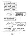
- Figure 4 is a flow diagram illustrating a process for transmission power control for communications between a first transceiver and a second transceiver under an embodiment of the invention.
- the first transceiver transmits a signal to the second transceiver, 405.
- the second transceiver evaluates a quality of the signal, 410.
- the second transceiver compares the quality of the signal to a reference value, 415. If the quality is greater than the reference quality, 420, the basic power control message requests a decrease in power by a predetermined amount, 425. In other cases the basic power control message requests an increase in power by a predetermined amount, 430.
- an extended power control message is included that requests a modification in transmission power by an amount specified in the extended power control message, 440.
- the second transceiver transmits a signal including the power control message, 445.
- the first transceiver adjusts its transmission power in response to the power control message, 450.
- the second transceiver ignores the basic power control message if an extended power control message is also received.
- the circumstances in which an extended power control message is included may vary.
- the extended power control message is included if the deviation exceeds the threshold for a certain number of consecutive bursts of data. Limiting the extended power control message to circumstances in which there are multiple occurrences of deviations outside of the established threshold minimizes situations in which there is a false triggering of the need for larger transmission power modifications because of a transitory change in signal quality.
- quality measurements for a received signal are averaged over time to obtain a time averaged signal quality, and the time averaged signal quality is compared to a reference signal quality.
- the extended power control message is included in a power control message if the deviation between the time averaged signal quality and the reference signal quality is more than a certain threshold. The use of a time average of signal quality reduces instances in which signal fluctuations of short duration cause unnecessary requests for transmission power modifications.
- the transmission of additional extended power modification messages may be suppressed for a certain period of time after an extended power control message has been transmitted.
- the suppression of a message for a certain period of time may allow a transmitter sufficient time to adjust the transmission power level as requested. If a second extended power control message is transmitted too soon after a first extended message, the second message may request an unnecessary adjustment causing the transmission power to overshoot the intended level and requiring another adjustment to fix the over correction.
- transmissions of the extended power change request may be suppressed for some period to minimize the use of the communication channel for power control messages that are not effective.
- transmission of the extended power may be suspended for the duration of the communication link.
- a signal modulation format may be adjustable.
- a high signal quality format may include a relatively large amount of data per burst of data
- a low signal quality format may include a relatively small amount of data per data burst.
- an extended power control message is included in each message utilizing a high signal quality format because the overhead required is low compared to the available data rate.
- an extended power control message is not included in a message utilizing a low signal quality format because the overhead required is high compared to the available data rate.
- the present invention relates to wireless communication systems and may be a fixed-access or mobile-access wireless network using spatial division multiple access (SDMA) technology in combination with multiple access systems, such as time division multiple access (TDMA), frequency division multiple access (FDMA) and code division multiple access (CDMA). Multiple access can be combined with frequency division duplexing (FDD) or time division duplexing (TDD).
- FIG 5 shows an example of a base station 500 of a wireless communications system or network suitable for implementing the present invention.
- the system or network includes a number of subscriber stations, also referred to as remote terminals or user terminals, such as that shown in Figure 6 .
- the base station 500 may be connected to a wide area network (WAN) through its host DSP 531 for providing any required data services and connections external to the immediate wireless system.
- WAN wide area network
- a plurality of antennas 503 is used, for example four antennas, although other numbers of antennas may be selected.
- a set of spatial multiplexing weights for each subscriber station are applied to the respective modulated signals to produce spatially multiplexed signals to be transmitted by the bank of four antennas.
- the host DSP 531 produces and maintains spatial signatures for each subscriber station for each conventional channel and calculates spatial multiplexing and demultiplexing weights using received signal measurements. In this manner, the signals from the current active subscriber stations, some of which may be active on the same conventional channel, are separated and interference and noise suppressed.
- an optimized multi-lobe antenna radiation pattern tailored to the current active subscriber station connections and interference situation is created. Suitable smart antenna technologies for achieving such a spatially directed beam are described, for example, in U.S. Patents Nos.
- the channels used may be partitioned in any manner.
- the channels used may be partitioned as defined in the GSM (Global System for Mobile Communications) air interface, or any other time division air interface protocol, such as Digital Cellular, PCS (Personal Communication System), PHS (Personal Handyphone System) or WLL (Wireless Local Loop).
- GSM Global System for Mobile Communications
- PCS Personal Computer System
- PHS Personal Handyphone System
- WLL Wireless Local Loop
- continuous analog or CDMA channels can be used.
- the outputs of the antennas are connected to a duplexer switch 507, which in a TDD embodiment, may be a time switch.
- a duplexer switch 507 which in a TDD embodiment, may be a time switch.
- Two possible implementations of the duplexer switch are as a frequency duplexer in a frequency division duplex (FDD) system, and as a time switch in a time division duplex (TDD) system.
- FDD frequency division duplex
- TDD time division duplex
- the antenna outputs are connected via the duplexer switch to a receiver 505 , and are converted down in analog by RF receiver (“RX") modules 505 from the carrier frequency to an FM intermediate frequency ("IF").
- RX RF receiver
- IF FM intermediate frequency
- ADCs analog to digital converters
- Final down-converting to baseband is carried out digitally.
- Digital filters can be used to implement the down-converting and the digital filtering, the latter using finite impulse response (FIR) filtering techniques. This is
- each antenna's digital filter 513 there are, in the present example, eight down-converted outputs from each antenna's digital filter 513, one per receive timeslot.
- the particular number of timeslots can be varied to suit network needs. While GSM uses eight uplink and eight downlink timeslots for each TDMA frame, desirable results can also be achieved with any number of TDMA timeslots for the uplink and downlink in each frame.
- DSP digital signal processor
- timeslot processor Eight Motorola DSP56300 Family DSPs can be used as timeslot processors, one per receive timeslot.
- the timeslot processors 517 monitor the received signal power and estimate the frequency offset and time alignment. They also determine smart antenna weights for each antenna element. These are used in the SDMA scheme to determine a signal from a particular remote user and to demodulate the determined signal.
- the output of the timeslot processors 517 is demodulated burst data for each of the eight receive timeslots.
- This data is sent to the host DSP processor 531 whose main function is to control all elements of the system and interface with the higher level processing, which is the processing which deals with what signals are required for communications in all the different control and service communication channels defined in the system's communication protocol.
- the host DSP 531 can be a Motorola DSP56300 Family DSP.
- timeslot processors send the determined receive weights for each user terminal to the host DSP 531.
- the host DSP 531 maintains state and timing information, receives uplink burst data from the timeslot processors 517, and programs the timeslot processors 517.
- DSP 531 may include a memory element to store data, instructions, or hopping functions or sequences.
- the base station 500 may have a separate memory element or have access to an auxiliary memory element.
- DSP 531 formats service data and traffic data for further higher processing in the base station 500, receives downlink messages and traffic data from the other parts of the base station 500, processes the downlink bursts and formats and sends the downlink bursts to a transmit controller/modulator, shown as 537.
- the host DSP also manages programming of other components of the base station 500 including the transmit controller/modulator 537 and the RF timing controller shown as 533.
- the RF controller 533 reads and transmits power monitoring and control values, controls the duplexer 507 and receives timing parameters and other settings for each burst from the host DSP 531.
- the transmit controller/modulator 537 receives transmit data from the host DSP 531.
- the transmit controller uses this data to produce analog IF outputs which are sent to the RF transmitter (TX) modules 539.
- TX RF transmitter
- the received data bits are converted into a complex modulated signal, up-converted to an IF frequency, sampled, multiplied by transmit weights obtained from host DSP 531, and converted via digital to analog converters ("DACs") which are part of transmit controller/modulator 537 to analog transmit waveforms.
- DACs digital to analog converters
- the analog waveforms are sent to the transmit modules 539.
- the transmit modules 539 up-convert the signals to the transmission frequency and amplify the signals.
- the amplified transmission signal outputs are sent to antennas 503 via the duplexer/time switch 507.
- FIG. 6 depicts an example component arrangement in a remote terminal 600 that provides data or voice communication.
- the remote terminal's 600 antenna 645 is connected to a duplexer 646 to permit the antenna 645 to be used for both transmission and reception.
- the antenna can be omni-directional or directional. For optimal performance, the antenna can be made up of multiple elements and employ spatial processing as discussed above for the base station 500. In an alternate embodiment, separate receive and transmit antennas are used eliminating the need for the duplexer 646 . In another alternate embodiment, where time division duplexing is used, a transmit/receive (TR) switch can be used instead of a duplexer as is well known in the art.
- TR transmit/receive
- the duplexer output 647 serves as input to a receiver 648.
- the receiver 648 produces a down-converted signal 649 , which is the input to a demodulator 651.
- a demodulated received sound or voice signal 667 is input to a speaker 670.
- the remote terminal 600 has a corresponding transmit chain in which data or voice to be transmitted is modulated in a modulator 657.
- the modulated signal to be transmitted 659, output by the modulator 657, is up-converted and amplified by a transmitter 660, producing a transmitter output signal 661.
- the transmitter output 661 is then input to the duplexer 646 for transmission by the antenna 645.
- the demodulated received data 652 is supplied to a remote terminal central processing unit 668 (CPU) as is received data before demodulation 650.
- the remote terminal CPU 668 can be implemented with a standard DSP (digital signal processor) device such as a Motorola series 56300 Family DSP. This DSP can also perform the functions of the demodulator 651 and the modulator 657.
- the remote terminal CPU 668 controls the receiver through line 663, the transmitter through line 662, the demodulator through line 652 and the modulator through line 658. It also communicates with a keyboard 653 through line 654 and a display 656 through line 655.
- a microphone 664 and speaker 670 are connected through the modulator 657 and the demodulator 651 through lines 665 and 667, respectively for a voice communications remote terminal.
- the microphone and speaker are also in direct communication with the CPU to provide voice or data communications.
- remote terminal CPU 668 may also include a memory element to store data, instructions, and hopping functions or sequences.
- the remote terminal 600 may have a separate memory element or have access to an auxiliary memory element.
- the speaker 670, and the microphone 664 are replaced or augmented by digital interfaces well-known in the art that allow data to be transmitted to and from an external data processing device (for example, a computer).
- the remote terminal's CPU 668 is coupled to a standard digital interface such as a PCMCIA interface to an external computer and the display, keyboard, microphone and speaker are a part of the external computer.
- the remote terminal's CPU 668 communicates with these components through the digital interface and the external computer's controller.
- the microphone and speaker can be deleted.
- the keyboard and display can be deleted.
- the present invention is described in the context of TDD (time division duplexing), but the invention is not limited to this context.
- the invention is also application to wireless systems in which a pilot signal typically is shared among multiple users at the same time, as is commonly required in standards for CDMA (code division multiple access) systems.
- Current examples of such wireless systems include WCDMA (wideband CDMA), cdma2000, IS-95, and HDR (high data rate) communications.
- WCDMA wideband CDMA
- cdma2000 cdma2000
- IS-95 high data rate
- HDR high data rate communications.
- the present system may also be applied to TDMA (time division multiple access) systems such as GSM (global system for mobile communications).
- the present invention includes various steps.
- the steps of the present invention may be performed by hardware components or may be embodied in machine-executable instructions, which may be used to cause a general-purpose or special-purpose processor or logic circuits programmed with the instructions to perform the steps.
- the steps may be performed by a combination of hardware and software.
- the steps have been described as being performed by either the base station or the user terminal. However, many of the steps described as being performed by the base station may be performed by the user terminal and vice versa.
- the invention is equally applicable to systems in which terminals communicate with each other without either one being designated as a base station, a user terminal, a remote terminal or a subscriber station.
- the present invention is equally applicable and useful in a peer-to-peer wireless network of communications devices using spatial processing. These devices may be cellular phones, PDA's, laptop computers, or any other wireless devices.
- these communications devices of wireless communications networks may be generally referred to as radios.
- the base station is described as performing spatial processing using an adaptive antenna array.
- the user terminals can also contain antenna arrays, and can also perform spatial processing both on receiving and transmitting (uplink and downlink) within the scope of the present invention. Any step or process attributed to the uplink can be instead performed on the downlink and vice versa.
- certain functions performed by a base station could be coordinated across the network, or assigned to other components of the system.
- the invention does not require the use of adaptive antennas, and may be implemented in any system in which two radios are in communication with each other.
- the present invention may be provided as a computer program product, which may include a machine-readable medium having stored thereon instructions, which may be used to program a computer (or other electronic devices) to perform a process according to the present invention.
- the machine-readable medium may include, but is not limited to, floppy diskettes, optical disks, CD-ROMs, and magneto-optical disks, ROMs, RAMs, EPROMs, EEPROMs, magnet or optical cards, flash memory, or other type of media / machine-readable medium suitable for storing electronic instructions.
- the present invention may also be downloaded as a computer program product, wherein the program may be transferred from a remote computer to a requesting computer by way of data signals embodied in a carrier wave or other propagation medium via a communication link (e.g., a modem or network connection).
- a communication link e.g., a modem or network connection
Landscapes
- Engineering & Computer Science (AREA)
- Computer Networks & Wireless Communication (AREA)
- Signal Processing (AREA)
- Mobile Radio Communication Systems (AREA)
Applications Claiming Priority (3)
| Application Number | Priority Date | Filing Date | Title |
|---|---|---|---|
| US189709 | 1994-02-01 | ||
| US10/189,709 US7269389B2 (en) | 2002-07-03 | 2002-07-03 | Selective power control messaging |
| PCT/US2003/020924 WO2004006465A1 (en) | 2002-07-03 | 2003-07-02 | Selective power control messaging |
Publications (2)
| Publication Number | Publication Date |
|---|---|
| EP1520354A1 EP1520354A1 (en) | 2005-04-06 |
| EP1520354B1 true EP1520354B1 (en) | 2012-01-18 |
Family
ID=29999704
Family Applications (1)
| Application Number | Title | Priority Date | Filing Date |
|---|---|---|---|
| EP03742421A Expired - Lifetime EP1520354B1 (en) | 2002-07-03 | 2003-07-02 | Selective power control messaging |
Country Status (8)
| Country | Link |
|---|---|
| US (1) | US7269389B2 (enExample) |
| EP (1) | EP1520354B1 (enExample) |
| JP (1) | JP4486884B2 (enExample) |
| KR (1) | KR101005509B1 (enExample) |
| CN (1) | CN100474789C (enExample) |
| AU (1) | AU2003281456A1 (enExample) |
| CA (1) | CA2491671C (enExample) |
| WO (1) | WO2004006465A1 (enExample) |
Families Citing this family (46)
| Publication number | Priority date | Publication date | Assignee | Title |
|---|---|---|---|---|
| US8363744B2 (en) | 2001-06-10 | 2013-01-29 | Aloft Media, Llc | Method and system for robust, secure, and high-efficiency voice and packet transmission over ad-hoc, mesh, and MIMO communication networks |
| US6947748B2 (en) | 2000-12-15 | 2005-09-20 | Adaptix, Inc. | OFDMA with adaptive subcarrier-cluster configuration and selective loading |
| US7190749B2 (en) * | 2001-06-06 | 2007-03-13 | Qualcomm Incorporated | Method and apparatus for canceling pilot interference in a wireless communication system |
| US8611311B2 (en) | 2001-06-06 | 2013-12-17 | Qualcomm Incorporated | Method and apparatus for canceling pilot interference in a wireless communication system |
| JP2004015655A (ja) * | 2002-06-10 | 2004-01-15 | Sony Corp | 通信装置 |
| US7257101B2 (en) * | 2002-07-03 | 2007-08-14 | Arraycomm, Llc | Selective power control messaging |
| US7269389B2 (en) | 2002-07-03 | 2007-09-11 | Arraycomm, Llc | Selective power control messaging |
| US8023950B2 (en) | 2003-02-18 | 2011-09-20 | Qualcomm Incorporated | Systems and methods for using selectable frame durations in a wireless communication system |
| US8391249B2 (en) | 2003-02-18 | 2013-03-05 | Qualcomm Incorporated | Code division multiplexing commands on a code division multiplexed channel |
| US7505780B2 (en) * | 2003-02-18 | 2009-03-17 | Qualcomm Incorporated | Outer-loop power control for wireless communication systems |
| US7155236B2 (en) | 2003-02-18 | 2006-12-26 | Qualcomm Incorporated | Scheduled and autonomous transmission and acknowledgement |
| US7660282B2 (en) | 2003-02-18 | 2010-02-09 | Qualcomm Incorporated | Congestion control in a wireless data network |
| US20040160922A1 (en) | 2003-02-18 | 2004-08-19 | Sanjiv Nanda | Method and apparatus for controlling data rate of a reverse link in a communication system |
| US8081598B2 (en) | 2003-02-18 | 2011-12-20 | Qualcomm Incorporated | Outer-loop power control for wireless communication systems |
| US8150407B2 (en) | 2003-02-18 | 2012-04-03 | Qualcomm Incorporated | System and method for scheduling transmissions in a wireless communication system |
| US8705588B2 (en) | 2003-03-06 | 2014-04-22 | Qualcomm Incorporated | Systems and methods for using code space in spread-spectrum communications |
| US7215930B2 (en) * | 2003-03-06 | 2007-05-08 | Qualcomm, Incorporated | Method and apparatus for providing uplink signal-to-noise ratio (SNR) estimation in a wireless communication |
| US8238956B1 (en) | 2003-03-14 | 2012-08-07 | Apple Inc. | Adjusting power of a control channel based on a characteristic of a message in the control channel |
| US8477592B2 (en) | 2003-05-14 | 2013-07-02 | Qualcomm Incorporated | Interference and noise estimation in an OFDM system |
| US8489949B2 (en) | 2003-08-05 | 2013-07-16 | Qualcomm Incorporated | Combining grant, acknowledgement, and rate control commands |
| US7403780B2 (en) * | 2004-02-19 | 2008-07-22 | Rockwell Collins, Inc. | Hybrid open/closed loop filtering for link quality estimation |
| KR100725773B1 (ko) * | 2004-08-20 | 2007-06-08 | 삼성전자주식회사 | 시분할 듀플렉스 방식의 이동통신 시스템에서 단말기의상태에 따라 상향링크 전력제어방식을 적응적으로변경하기 위한 장치 및 방법 |
| JP4687047B2 (ja) * | 2004-09-21 | 2011-05-25 | 株式会社ケンウッド | 無線通信制御装置及び無線通信方法 |
| US7515877B2 (en) * | 2004-11-04 | 2009-04-07 | Magnolia Broadband Inc. | Communicating signals according to a quality indicator and a time boundary indicator |
| CN100550676C (zh) * | 2004-12-02 | 2009-10-14 | 中兴通讯股份有限公司 | 移动通讯系统内终端前向发射功率控制门限的调整方法 |
| US7573851B2 (en) | 2004-12-07 | 2009-08-11 | Adaptix, Inc. | Method and system for switching antenna and channel assignments in broadband wireless networks |
| US8099123B2 (en) * | 2004-12-23 | 2012-01-17 | Qualcomm Incorporated | Adaptation of transmit subchannel gains in a system with interference cancellation |
| US8406695B2 (en) * | 2004-12-23 | 2013-03-26 | Qualcomm Incorporated | Joint interference cancellation of pilot, overhead and traffic channels |
| US8422955B2 (en) | 2004-12-23 | 2013-04-16 | Qualcomm Incorporated | Channel estimation for interference cancellation |
| US8442441B2 (en) | 2004-12-23 | 2013-05-14 | Qualcomm Incorporated | Traffic interference cancellation |
| US20060262874A1 (en) * | 2005-05-17 | 2006-11-23 | Interdigital Technology Corporation | Method and apparatus for power control in a multiple antenna system |
| JP4895557B2 (ja) * | 2005-09-16 | 2012-03-14 | パナソニック株式会社 | マルチキャリア通信装置、及びマルチキャリア通信方法 |
| US8472877B2 (en) | 2005-10-24 | 2013-06-25 | Qualcomm Incorporated | Iterative interference cancellation system and method |
| US8385388B2 (en) | 2005-12-06 | 2013-02-26 | Qualcomm Incorporated | Method and system for signal reconstruction from spatially and temporally correlated received samples |
| KR100842648B1 (ko) * | 2006-01-19 | 2008-06-30 | 삼성전자주식회사 | 무선 통신 시스템에서 전력 제어 장치 및 방법 |
| US20070191045A1 (en) * | 2006-02-15 | 2007-08-16 | Mark Kent | Method and system for synchronization procedures in a wide band CDMA network based on a sign metric |
| US7907961B2 (en) | 2006-06-07 | 2011-03-15 | Broadcom Corporation | Method and apparatus for improving noise power estimate in a WCDMA network |
| CN101494894B (zh) * | 2008-12-31 | 2011-01-19 | 中兴通讯股份有限公司 | 反向功率控制方法及控制装置 |
| US8855570B2 (en) * | 2009-02-05 | 2014-10-07 | Telefonaktiebolaget L M Ericsson (Publ) | Coexistence of plural wireless communication transceivers in close proximity |
| JP5083462B2 (ja) * | 2009-04-24 | 2012-11-28 | 日本電気株式会社 | 通信システム |
| WO2010145987A1 (en) * | 2009-06-17 | 2010-12-23 | Telefonaktiebolaget L M Ericsson (Publ) | Transmit power control of channels transmitted in different frequency regions |
| EP2355593B1 (en) * | 2010-01-28 | 2015-09-16 | Alcatel Lucent | Network node control |
| KR20120006259A (ko) * | 2010-07-12 | 2012-01-18 | 삼성전자주식회사 | 이동 통신 시스템에서 업링크 송신 전력 상태 보고 장치 및 방법 |
| CN102448072B (zh) * | 2010-10-12 | 2016-01-20 | 中国移动通信集团甘肃有限公司 | 无线网络覆盖控制方法、装置及系统 |
| CN102137479B (zh) * | 2011-03-02 | 2014-07-23 | 清华大学 | 一种分布式天线架构中下行功率控制的方法 |
| JP2020205473A (ja) * | 2019-06-14 | 2020-12-24 | 株式会社村田製作所 | 通信回路及び通信回路の制御方法 |
Family Cites Families (17)
| Publication number | Priority date | Publication date | Assignee | Title |
|---|---|---|---|---|
| US5396516A (en) * | 1993-02-22 | 1995-03-07 | Qualcomm Incorporated | Method and system for the dynamic modification of control paremeters in a transmitter power control system |
| US6075974A (en) | 1996-11-20 | 2000-06-13 | Qualcomm Inc. | Method and apparatus for adjusting thresholds and measurements of received signals by anticipating power control commands yet to be executed |
| US6396867B1 (en) | 1997-04-25 | 2002-05-28 | Qualcomm Incorporated | Method and apparatus for forward link power control |
| US6744754B1 (en) | 1998-06-09 | 2004-06-01 | Lg Information & Communications, Ltd. | Control of forward link power CDMA mobile communication system |
| EP0977370B1 (en) | 1998-07-28 | 2005-10-05 | Lucent Technologies Inc. | Transmission power control for packet switched communication systems |
| GB9819113D0 (en) | 1998-09-02 | 1998-10-28 | Roke Manor Research | Measurement improvement in W-CDMA |
| KR100277071B1 (ko) | 1998-09-15 | 2001-01-15 | 윤종용 | 셀룰러시스템의역방향전력제어방법 |
| US6519236B1 (en) | 1998-09-18 | 2003-02-11 | Telefonaktiebolaget Lm Ericsson (Publ) | Automatic power control in uncoordinated frequency-hopping radio systems |
| BR9816101A (pt) * | 1998-12-07 | 2002-02-05 | Nokia Networks Oy | Processo e sistema para realizar controle de potência em uma rede de comunicação móvel, elemento de rede e estação base |
| US6418137B1 (en) | 1998-12-14 | 2002-07-09 | Nortel Networks Limited | Transmitted signal power control in cellular communications systems |
| JP2000286791A (ja) * | 1999-03-31 | 2000-10-13 | Matsushita Electric Ind Co Ltd | 移動体通信システム |
| US6334047B1 (en) * | 1999-04-09 | 2001-12-25 | Telefonaktiebolaget Lm Ericsson (Publ) | Adaptive power control in a mobile radio communications system |
| US6823193B1 (en) | 2000-02-28 | 2004-11-23 | Telefonaktiebolaget Lm Ericsson (Publ) | Downlink transmit power synchronization during diversity communication with a mobile station |
| SE0101169D0 (sv) | 2000-10-17 | 2001-03-30 | Ericsson Telefon Ab L M | Method and system of transmission power control |
| DE60238732D1 (de) * | 2001-01-18 | 2011-02-10 | Ntt Docomo Inc | Vorrichtung und Verfahren zur Sendeleistungsregelung und Mobilstation |
| US7269389B2 (en) | 2002-07-03 | 2007-09-11 | Arraycomm, Llc | Selective power control messaging |
| US7257101B2 (en) | 2002-07-03 | 2007-08-14 | Arraycomm, Llc | Selective power control messaging |
-
2002
- 2002-07-03 US US10/189,709 patent/US7269389B2/en not_active Expired - Lifetime
-
2003
- 2003-07-02 KR KR1020057000074A patent/KR101005509B1/ko not_active Expired - Fee Related
- 2003-07-02 EP EP03742421A patent/EP1520354B1/en not_active Expired - Lifetime
- 2003-07-02 WO PCT/US2003/020924 patent/WO2004006465A1/en not_active Ceased
- 2003-07-02 JP JP2004519821A patent/JP4486884B2/ja not_active Expired - Lifetime
- 2003-07-02 CN CNB038201380A patent/CN100474789C/zh not_active Expired - Lifetime
- 2003-07-02 CA CA2491671A patent/CA2491671C/en not_active Expired - Lifetime
- 2003-07-02 AU AU2003281456A patent/AU2003281456A1/en not_active Abandoned
Also Published As
| Publication number | Publication date |
|---|---|
| JP2005532739A (ja) | 2005-10-27 |
| CA2491671C (en) | 2012-09-11 |
| US20040005905A1 (en) | 2004-01-08 |
| JP4486884B2 (ja) | 2010-06-23 |
| AU2003281456A1 (en) | 2004-01-23 |
| CN1679254A (zh) | 2005-10-05 |
| WO2004006465A1 (en) | 2004-01-15 |
| CN100474789C (zh) | 2009-04-01 |
| EP1520354A1 (en) | 2005-04-06 |
| KR101005509B1 (ko) | 2011-01-04 |
| KR20050016763A (ko) | 2005-02-21 |
| CA2491671A1 (en) | 2004-01-15 |
| US7269389B2 (en) | 2007-09-11 |
Similar Documents
| Publication | Publication Date | Title |
|---|---|---|
| EP1520354B1 (en) | Selective power control messaging | |
| EP1547272B1 (en) | Selective power control messaging | |
| EP1547287B1 (en) | Transmission link adaptation | |
| JP4008507B2 (ja) | 無線通信システムにおける多重符号チャネルのパワーコントロール | |
| US5761622A (en) | Method and apparatus for controlling operation of a portable or mobile battery-operated radios | |
| JP3078330B2 (ja) | Cdma通信システムにおける遠隔送信機電力制御 | |
| IL112487A (en) | Method and apparatus for providing a communication link quality indication | |
| GB2444565A (en) | Base station repeater | |
| EP1547288B1 (en) | Messaging for transmission link adaptation | |
| KR20050095634A (ko) | 무선 통신 시스템, 기지국 장치 및 그것에 이용하는 하향 송신 지향 특성 제어 방법 및 기록 매체 | |
| HK1084791B (en) | Method and system for power control during the traffic channel initialization period in a cdma network | |
| HK1084791A1 (en) | Method and system for power control during the traffic channel initialization period in a cdma network |
Legal Events
| Date | Code | Title | Description |
|---|---|---|---|
| PUAI | Public reference made under article 153(3) epc to a published international application that has entered the european phase |
Free format text: ORIGINAL CODE: 0009012 |
|
| 17P | Request for examination filed |
Effective date: 20050202 |
|
| AK | Designated contracting states |
Kind code of ref document: A1 Designated state(s): AT BE BG CH CY CZ DE DK EE ES FI FR GB GR HU IE IT LI LU MC NL PT RO SE SI SK TR |
|
| AX | Request for extension of the european patent |
Extension state: AL LT LV MK |
|
| DAX | Request for extension of the european patent (deleted) | ||
| RBV | Designated contracting states (corrected) |
Designated state(s): DE FR GB |
|
| RAP1 | Party data changed (applicant data changed or rights of an application transferred) |
Owner name: ARRAYCOMM LLC |
|
| RAP1 | Party data changed (applicant data changed or rights of an application transferred) |
Owner name: INTEL CORPORATION |
|
| 17Q | First examination report despatched |
Effective date: 20100507 |
|
| REG | Reference to a national code |
Ref country code: DE Ref legal event code: R079 Ref document number: 60339763 Country of ref document: DE Free format text: PREVIOUS MAIN CLASS: H04B0007005000 Ipc: H04W0052580000 |
|
| GRAP | Despatch of communication of intention to grant a patent |
Free format text: ORIGINAL CODE: EPIDOSNIGR1 |
|
| RIC1 | Information provided on ipc code assigned before grant |
Ipc: H04W 52/36 20090101ALN20110711BHEP Ipc: H04W 52/58 20090101AFI20110711BHEP |
|
| GRAS | Grant fee paid |
Free format text: ORIGINAL CODE: EPIDOSNIGR3 |
|
| GRAA | (expected) grant |
Free format text: ORIGINAL CODE: 0009210 |
|
| AK | Designated contracting states |
Kind code of ref document: B1 Designated state(s): DE FR GB |
|
| REG | Reference to a national code |
Ref country code: GB Ref legal event code: FG4D |
|
| REG | Reference to a national code |
Ref country code: DE Ref legal event code: R096 Ref document number: 60339763 Country of ref document: DE Effective date: 20120315 |
|
| PLBE | No opposition filed within time limit |
Free format text: ORIGINAL CODE: 0009261 |
|
| STAA | Information on the status of an ep patent application or granted ep patent |
Free format text: STATUS: NO OPPOSITION FILED WITHIN TIME LIMIT |
|
| 26N | No opposition filed |
Effective date: 20121019 |
|
| REG | Reference to a national code |
Ref country code: DE Ref legal event code: R097 Ref document number: 60339763 Country of ref document: DE Effective date: 20121019 |
|
| REG | Reference to a national code |
Ref country code: FR Ref legal event code: ST Effective date: 20130329 |
|
| PG25 | Lapsed in a contracting state [announced via postgrant information from national office to epo] |
Ref country code: FR Free format text: LAPSE BECAUSE OF NON-PAYMENT OF DUE FEES Effective date: 20120731 |
|
| REG | Reference to a national code |
Ref country code: DE Ref legal event code: R082 Ref document number: 60339763 Country of ref document: DE Representative=s name: MARKS & CLERK (LUXEMBOURG) LLP, LU Ref country code: DE Ref legal event code: R081 Ref document number: 60339763 Country of ref document: DE Owner name: APPLE INC., CUPERTINO, US Free format text: FORMER OWNER: INTEL CORPORATION, SANTA CLARA, CALIF., US |
|
| PGFP | Annual fee paid to national office [announced via postgrant information from national office to epo] |
Ref country code: GB Payment date: 20220606 Year of fee payment: 20 |
|
| PGFP | Annual fee paid to national office [announced via postgrant information from national office to epo] |
Ref country code: DE Payment date: 20220517 Year of fee payment: 20 |
|
| REG | Reference to a national code |
Ref country code: DE Ref legal event code: R071 Ref document number: 60339763 Country of ref document: DE |
|
| P01 | Opt-out of the competence of the unified patent court (upc) registered |
Effective date: 20230526 |
|
| REG | Reference to a national code |
Ref country code: GB Ref legal event code: PE20 Expiry date: 20230701 |
|
| PG25 | Lapsed in a contracting state [announced via postgrant information from national office to epo] |
Ref country code: GB Free format text: LAPSE BECAUSE OF EXPIRATION OF PROTECTION Effective date: 20230701 |
|
| REG | Reference to a national code |
Ref country code: GB Ref legal event code: 732E Free format text: REGISTERED BETWEEN 20250306 AND 20250312 |