EP1520215B1 - Dynamische online-optimierung von produktionsprozessen - Google Patents
Dynamische online-optimierung von produktionsprozessen Download PDFInfo
- Publication number
- EP1520215B1 EP1520215B1 EP03736394A EP03736394A EP1520215B1 EP 1520215 B1 EP1520215 B1 EP 1520215B1 EP 03736394 A EP03736394 A EP 03736394A EP 03736394 A EP03736394 A EP 03736394A EP 1520215 B1 EP1520215 B1 EP 1520215B1
- Authority
- EP
- European Patent Office
- Prior art keywords
- variables
- output variables
- time interval
- objective function
- production
- Prior art date
- Legal status (The legal status is an assumption and is not a legal conclusion. Google has not performed a legal analysis and makes no representation as to the accuracy of the status listed.)
- Expired - Lifetime
Links
- 238000004519 manufacturing process Methods 0.000 title claims abstract description 100
- 238000005457 optimization Methods 0.000 title abstract description 40
- 238000000034 method Methods 0.000 claims abstract description 425
- 230000008569 process Effects 0.000 claims abstract description 346
- 239000000126 substance Substances 0.000 claims abstract description 80
- 239000000654 additive Substances 0.000 claims abstract description 34
- 230000036962 time dependent Effects 0.000 claims abstract description 11
- 239000000872 buffer Substances 0.000 claims description 80
- 230000001419 dependent effect Effects 0.000 claims description 15
- 230000001276 controlling effect Effects 0.000 claims description 14
- 239000013626 chemical specie Substances 0.000 claims description 12
- 238000009826 distribution Methods 0.000 claims description 10
- 238000012544 monitoring process Methods 0.000 claims description 10
- 238000012432 intermediate storage Methods 0.000 claims description 7
- 230000001105 regulatory effect Effects 0.000 claims description 7
- 238000004590 computer program Methods 0.000 claims description 5
- 238000004891 communication Methods 0.000 claims description 4
- 230000010354 integration Effects 0.000 claims description 4
- 230000000996 additive effect Effects 0.000 claims 2
- 238000009499 grossing Methods 0.000 claims 1
- 238000005259 measurement Methods 0.000 abstract description 20
- 230000006870 function Effects 0.000 description 25
- NINIDFKCEFEMDL-UHFFFAOYSA-N Sulfur Chemical compound [S] NINIDFKCEFEMDL-UHFFFAOYSA-N 0.000 description 18
- 229910052717 sulfur Inorganic materials 0.000 description 18
- 239000011593 sulfur Substances 0.000 description 18
- 239000011734 sodium Substances 0.000 description 17
- 229910052708 sodium Inorganic materials 0.000 description 17
- DGAQECJNVWCQMB-PUAWFVPOSA-M Ilexoside XXIX Chemical compound C[C@@H]1CC[C@@]2(CC[C@@]3(C(=CC[C@H]4[C@]3(CC[C@@H]5[C@@]4(CC[C@@H](C5(C)C)OS(=O)(=O)[O-])C)C)[C@@H]2[C@]1(C)O)C)C(=O)O[C@H]6[C@@H]([C@H]([C@@H]([C@H](O6)CO)O)O)O.[Na+] DGAQECJNVWCQMB-PUAWFVPOSA-M 0.000 description 16
- 238000010586 diagram Methods 0.000 description 12
- 239000000463 material Substances 0.000 description 10
- HEMHJVSKTPXQMS-UHFFFAOYSA-M Sodium hydroxide Chemical compound [OH-].[Na+] HEMHJVSKTPXQMS-UHFFFAOYSA-M 0.000 description 9
- 230000009471 action Effects 0.000 description 9
- 230000008859 change Effects 0.000 description 9
- 239000000203 mixture Substances 0.000 description 8
- 238000013459 approach Methods 0.000 description 7
- 230000000694 effects Effects 0.000 description 7
- 238000011112 process operation Methods 0.000 description 7
- 239000000047 product Substances 0.000 description 7
- CDBYLPFSWZWCQE-UHFFFAOYSA-L Sodium Carbonate Chemical compound [Na+].[Na+].[O-]C([O-])=O CDBYLPFSWZWCQE-UHFFFAOYSA-L 0.000 description 6
- 239000007787 solid Substances 0.000 description 6
- 241000196324 Embryophyta Species 0.000 description 5
- 239000000428 dust Substances 0.000 description 5
- 238000005070 sampling Methods 0.000 description 5
- VTYYLEPIZMXCLO-UHFFFAOYSA-L Calcium carbonate Chemical compound [Ca+2].[O-]C([O-])=O VTYYLEPIZMXCLO-UHFFFAOYSA-L 0.000 description 4
- 235000008733 Citrus aurantifolia Nutrition 0.000 description 4
- PMZURENOXWZQFD-UHFFFAOYSA-L Sodium Sulfate Chemical compound [Na+].[Na+].[O-]S([O-])(=O)=O PMZURENOXWZQFD-UHFFFAOYSA-L 0.000 description 4
- 235000011941 Tilia x europaea Nutrition 0.000 description 4
- 238000006243 chemical reaction Methods 0.000 description 4
- 238000010411 cooking Methods 0.000 description 4
- 239000000945 filler Substances 0.000 description 4
- 239000004571 lime Substances 0.000 description 4
- 239000002994 raw material Substances 0.000 description 4
- 229910052938 sodium sulfate Inorganic materials 0.000 description 4
- 239000002699 waste material Substances 0.000 description 4
- XLYOFNOQVPJJNP-UHFFFAOYSA-N water Substances O XLYOFNOQVPJJNP-UHFFFAOYSA-N 0.000 description 4
- 239000007832 Na2SO4 Substances 0.000 description 3
- 241001062472 Stokellia anisodon Species 0.000 description 3
- QAOWNCQODCNURD-UHFFFAOYSA-L Sulfate Chemical compound [O-]S([O-])(=O)=O QAOWNCQODCNURD-UHFFFAOYSA-L 0.000 description 3
- 230000006399 behavior Effects 0.000 description 3
- 230000008901 benefit Effects 0.000 description 3
- 239000007795 chemical reaction product Substances 0.000 description 3
- 150000001875 compounds Chemical class 0.000 description 3
- 238000013500 data storage Methods 0.000 description 3
- 238000013461 design Methods 0.000 description 3
- 239000000835 fiber Substances 0.000 description 3
- 238000012423 maintenance Methods 0.000 description 3
- 238000004886 process control Methods 0.000 description 3
- 229910000029 sodium carbonate Inorganic materials 0.000 description 3
- 239000002023 wood Substances 0.000 description 3
- BVKZGUZCCUSVTD-UHFFFAOYSA-L Carbonate Chemical compound [O-]C([O-])=O BVKZGUZCCUSVTD-UHFFFAOYSA-L 0.000 description 2
- 241000202567 Fatsia japonica Species 0.000 description 2
- QAOWNCQODCNURD-UHFFFAOYSA-N Sulfuric acid Chemical compound OS(O)(=O)=O QAOWNCQODCNURD-UHFFFAOYSA-N 0.000 description 2
- UCKMPCXJQFINFW-UHFFFAOYSA-N Sulphide Chemical compound [S-2] UCKMPCXJQFINFW-UHFFFAOYSA-N 0.000 description 2
- RAHZWNYVWXNFOC-UHFFFAOYSA-N Sulphur dioxide Chemical compound O=S=O RAHZWNYVWXNFOC-UHFFFAOYSA-N 0.000 description 2
- QVGXLLKOCUKJST-UHFFFAOYSA-N atomic oxygen Chemical compound [O] QVGXLLKOCUKJST-UHFFFAOYSA-N 0.000 description 2
- 229910000019 calcium carbonate Inorganic materials 0.000 description 2
- AXCZMVOFGPJBDE-UHFFFAOYSA-L calcium dihydroxide Chemical compound [OH-].[OH-].[Ca+2] AXCZMVOFGPJBDE-UHFFFAOYSA-L 0.000 description 2
- 239000000920 calcium hydroxide Substances 0.000 description 2
- 229910001861 calcium hydroxide Inorganic materials 0.000 description 2
- 238000004364 calculation method Methods 0.000 description 2
- 239000003795 chemical substances by application Substances 0.000 description 2
- 238000002485 combustion reaction Methods 0.000 description 2
- 230000007423 decrease Effects 0.000 description 2
- 238000001704 evaporation Methods 0.000 description 2
- 230000008020 evaporation Effects 0.000 description 2
- 238000009472 formulation Methods 0.000 description 2
- 239000011121 hardwood Substances 0.000 description 2
- 230000014759 maintenance of location Effects 0.000 description 2
- 238000002156 mixing Methods 0.000 description 2
- 229910052760 oxygen Inorganic materials 0.000 description 2
- 239000001301 oxygen Substances 0.000 description 2
- 238000011084 recovery Methods 0.000 description 2
- 230000008439 repair process Effects 0.000 description 2
- 229910052979 sodium sulfide Inorganic materials 0.000 description 2
- GRVFOGOEDUUMBP-UHFFFAOYSA-N sodium sulfide (anhydrous) Chemical compound [Na+].[Na+].[S-2] GRVFOGOEDUUMBP-UHFFFAOYSA-N 0.000 description 2
- GEHJYWRUCIMESM-UHFFFAOYSA-L sodium sulfite Chemical compound [Na+].[Na+].[O-]S([O-])=O GEHJYWRUCIMESM-UHFFFAOYSA-L 0.000 description 2
- 239000011122 softwood Substances 0.000 description 2
- 230000005477 standard model Effects 0.000 description 2
- 229920002488 Hemicellulose Polymers 0.000 description 1
- 229920001131 Pulp (paper) Polymers 0.000 description 1
- 238000007792 addition Methods 0.000 description 1
- 239000003513 alkali Substances 0.000 description 1
- 238000010923 batch production Methods 0.000 description 1
- 238000004061 bleaching Methods 0.000 description 1
- 239000007844 bleaching agent Substances 0.000 description 1
- 239000006227 byproduct Substances 0.000 description 1
- 150000001720 carbohydrates Chemical class 0.000 description 1
- 235000014633 carbohydrates Nutrition 0.000 description 1
- 239000001913 cellulose Substances 0.000 description 1
- 229920002678 cellulose Polymers 0.000 description 1
- 238000004140 cleaning Methods 0.000 description 1
- 238000012885 constant function Methods 0.000 description 1
- 230000003247 decreasing effect Effects 0.000 description 1
- 238000004821 distillation Methods 0.000 description 1
- 239000012717 electrostatic precipitator Substances 0.000 description 1
- 230000007613 environmental effect Effects 0.000 description 1
- 235000013305 food Nutrition 0.000 description 1
- 238000007429 general method Methods 0.000 description 1
- 230000008570 general process Effects 0.000 description 1
- RWSOTUBLDIXVET-UHFFFAOYSA-M hydrosulfide Chemical compound [SH-] RWSOTUBLDIXVET-UHFFFAOYSA-M 0.000 description 1
- XLYOFNOQVPJJNP-UHFFFAOYSA-M hydroxide Chemical compound [OH-] XLYOFNOQVPJJNP-UHFFFAOYSA-M 0.000 description 1
- 230000001771 impaired effect Effects 0.000 description 1
- 229910052500 inorganic mineral Inorganic materials 0.000 description 1
- 230000001788 irregular Effects 0.000 description 1
- 229920005610 lignin Polymers 0.000 description 1
- 239000011159 matrix material Substances 0.000 description 1
- 230000007246 mechanism Effects 0.000 description 1
- 230000005055 memory storage Effects 0.000 description 1
- 229910052751 metal Inorganic materials 0.000 description 1
- 239000002184 metal Substances 0.000 description 1
- 239000011707 mineral Substances 0.000 description 1
- 238000012986 modification Methods 0.000 description 1
- 230000004048 modification Effects 0.000 description 1
- 150000002898 organic sulfur compounds Chemical class 0.000 description 1
- 238000002203 pretreatment Methods 0.000 description 1
- 238000004540 process dynamic Methods 0.000 description 1
- 238000012545 processing Methods 0.000 description 1
- 238000004537 pulping Methods 0.000 description 1
- 238000010926 purge Methods 0.000 description 1
- 230000003134 recirculating effect Effects 0.000 description 1
- 238000004064 recycling Methods 0.000 description 1
- 230000009467 reduction Effects 0.000 description 1
- 230000004044 response Effects 0.000 description 1
- 230000035945 sensitivity Effects 0.000 description 1
- 239000002002 slurry Substances 0.000 description 1
- ZNCPFRVNHGOPAG-UHFFFAOYSA-L sodium oxalate Chemical compound [Na+].[Na+].[O-]C(=O)C([O-])=O ZNCPFRVNHGOPAG-UHFFFAOYSA-L 0.000 description 1
- 229940039790 sodium oxalate Drugs 0.000 description 1
- 235000011152 sodium sulphate Nutrition 0.000 description 1
- 235000010265 sodium sulphite Nutrition 0.000 description 1
- 239000002904 solvent Substances 0.000 description 1
- 241000894007 species Species 0.000 description 1
- 238000003860 storage Methods 0.000 description 1
- 150000003464 sulfur compounds Chemical class 0.000 description 1
- 230000009466 transformation Effects 0.000 description 1
- 230000001052 transient effect Effects 0.000 description 1
- 238000013519 translation Methods 0.000 description 1
- 238000005406 washing Methods 0.000 description 1
Images




Classifications
-
- D—TEXTILES; PAPER
- D21—PAPER-MAKING; PRODUCTION OF CELLULOSE
- D21G—CALENDERS; ACCESSORIES FOR PAPER-MAKING MACHINES
- D21G9/00—Other accessories for paper-making machines
- D21G9/0009—Paper-making control systems
- D21G9/0018—Paper-making control systems controlling the stock preparation
-
- G—PHYSICS
- G05—CONTROLLING; REGULATING
- G05B—CONTROL OR REGULATING SYSTEMS IN GENERAL; FUNCTIONAL ELEMENTS OF SUCH SYSTEMS; MONITORING OR TESTING ARRANGEMENTS FOR SUCH SYSTEMS OR ELEMENTS
- G05B13/00—Adaptive control systems, i.e. systems automatically adjusting themselves to have a performance which is optimum according to some preassigned criterion
- G05B13/02—Adaptive control systems, i.e. systems automatically adjusting themselves to have a performance which is optimum according to some preassigned criterion electric
- G05B13/04—Adaptive control systems, i.e. systems automatically adjusting themselves to have a performance which is optimum according to some preassigned criterion electric involving the use of models or simulators
- G05B13/048—Adaptive control systems, i.e. systems automatically adjusting themselves to have a performance which is optimum according to some preassigned criterion electric involving the use of models or simulators using a predictor
Definitions
- the present invention relates generally to a method and a system for production processes and in particular to optimization of process operation conditions.
- the present invention is particularly well suited for pulp and/or paper production processes.
- each process section In manufacturing of pulp and paper, the production is typically divided in a number of process sections connected to each other in a more or less complex pattern. Examples of process sections could be digesters, washing arrangements, refiners, bleaching arrangements, etc.
- the part process of each process section is typically a complex process, where the output flow from the process section and its properties depends on the present input flow (including its properties) of material, chemical additives, process operational conditions as well as of the previous history of operation of the process section. This means that the output is not only dependent on present conditions, but also on how the process section was operated in an earlier stage, i.e. there is a dynamic relation between variables of different kinds.
- a pulp and paper production line therefore typically comprises also process sections taking care of extracted chemical substances.
- the flow and properties of such chemical substances through the process are connected to operational conditions in an even more complex manner. In particular, the dependence on process history is even more pronounced than for the pulp flow itself.
- control of the flow of chemical additives is typically of a very simple type. If a shortage of chemicals appears, more chemicals are added, if an excess of chemicals appears, the excess is wasted.
- an on-line optimized pulp or paper production process is disclosed.
- a number of inputs such as raw material as well as chemicals, energy etc. are mentioned as important to optimize the process.
- the outputs which are considered, are typically production quantity, quality properties, and price as well as waste product quantities.
- the actual optimizing procedure is only described in general terms as an automatically calibrating module. The method is probably intended for off-line optimization of set-points in different typical steady-state situations. Difficulties arising from differences in the previous history of operation are not addressed at all.
- the optimization basically concerns the process as one entity, where only inputs and outputs of the entire process are discussed, even if bottleneck problems are mentioned.
- Another example of optimizing a process as one entity is known from US 6,319,362 B1 , where a method for controlling properties of paper is described.
- the method comprises modeling the effect of the flow of retention agent both on the amount of filler in white water and on the paper ash content, and of the effect of the flow of filler on the paper ash content and on the amount of filler in the white water, and adjusting simultaneously the amount of retention agent and the amount of filler.
- the optimization is carried out to optimize the controls based on the models, separate stored controls, measurements, disturbance variables and restrictions.
- Control systems according to prior art are typically based on an assumption of a substantially failure-free operation. In case a failure occurs and a process section temporarily has to be taken out of operation, there might not be enough buffers ensuring a continuous operation for the rest of the process sections. Such discontinuities may affect both the quality and the quantity of the end product as well as other cost related properties. In particular in systems having pronounced bottlenecks, problems with continuity may occur during minor disruptions.
- An object of the present invention is thus to provide a system and method, in particular for pulp and paper production, being capable of handling systems having dynamic processes with relatively large time constants.
- a further object of the present invention is to provide a system and method, in particular for pulp and paper production that can optimize the utilization of chemical additives in the process.
- Another object is to provide a system and method offering a flexible possibility to handle bottleneck problems.
- the method comprises the known steps of obtaining a dynamic process model having relations between manipulated variables and process output variables, providing external constraints for the production process, measuring a set of process output variables of the production process, defining an objective function, optimizing the objective function and operating the production process by setting the manipulated variables.
- the dynamic process model includes time dependent relations between the manipulated variables for said process sections and the process output variables from respective process section.
- an initial state is estimated.
- the external constraints for the production process are provided for a prediction time interval; and the objective function involves predicted controlled process output variables for the prediction time interval and the external constraints.
- the predicted controlled process output variables are defined by the dynamic process model based on the initial state.
- the objective function is optimized under constraints imposed by the dynamic process model and/or the external constraints, by adapting the manipulated variables, giving input trajectories for the manipulated variables for the prediction time interval.
- the production process is operated by setting the manipulated variables according to the input trajectories during a control time interval, where the control time interval is a part of the prediction time interval.
- a process is modeled by a dynamic model, handling time dependent relations between manipulated variables of different process sections and the process output variables of respective process section.
- a number of state variables are measured, and previous measurements are preferably also available.
- Suggested input trajectories for manipulated variables for a subsequent time period are obtained by optimizing an objective function over a prediction time period, under constraints imposed by the dynamic process model and preferably a production plan for the same period.
- the objective function comprises relations involving predictions of controlled process output variables as a function of time for the prediction time period using the process model, based on the present and preferably also previous measurements of state variables. In such a manner, dynamic behaviors of the process are handled.
- a prediction horizon also planned future operational changes can be prepared for, reducing any induced fluctuations.
- the dynamic model is based on dynamic section models, modeling the actual process of the different process sections, preferably interconnected by intermediate storage models, such as buffer models or buffer tank models. Flows between the different sections are process output variables or manipulated variables.
- process output variables associated with chemical additives and in particular the amount of chemicals, the distribution of chemicals over the system and the consumption of chemicals
- the optimisation can be adapted to handle optimizing aspects concerning chemical additives.
- other optimization aspects such as handling of bottleneck processes and minor failures in exposed process sections are also treated.
- State estimation techniques are preferably used for pre-treatment of the actually measured variables to be able to generate an initial state for the future optimization.
- the method and the system according to the invention may be used to carry out on a production process, preferably a pulp and/or paper production process, any of the operations of: monitoring, controlling, regulating, simulating, optimising, providing support for decisions, advising.
- a process is at every time characterized by a number of state variables.
- state variables can in a general view be of almost any kind and is here used as a common term for all possible variables concerning the state of a process.
- a process or a section thereof is typically controlled by setting a number of manipulated variables .
- manipulated variables are state variables that are easy to influence and that have a significant relevance for the operation of the process.
- manipulated variables can e.g. be the input flow of material or additives into a process, easily regulated by controlling e.g. a valve.
- process output variables The result of a control action is represented by a set of state variables, in the present disclosure called process output variables.
- a subset of these process output variables is suitable for monitoring the control action.
- Such variables are here called controlled process output variables.
- the purpose of the control action is to bring the controlled process output variables close to pre-determined set-points or set-point functions.
- State variables characterizing the result of the process control, but not directly used for controlling purposes, are in the present disclosure called associated process output variables.
- Some state variables are easy to measure more or less directly by different sensors. Such variables are called measurable variables. Other state variables may be difficult or even impossible to measure in a direct manner. Instead, another related quantity or quantities is(are) measured, and the actual state variable is estimated through more or less complex models or relations. Such variables are called derivable variables.
- a typical way to handle flow variations in the interface between different process sections is to introduce buffer tanks.
- the absolute output flow from a preceding process section does not limit the operation of a subsequent process section, if only the average output flow is sufficient.
- the exact level of the buffer tank is of minor importance in each moment.
- a model of a complex production process is based on the division into a number of standard model objects.
- the total model thereby comprises a number of section models, corresponding to the different process sections, a group of process sections or a part of one process section.
- the section models are connected to each other via model objects, basically representing intermediate storages, here in the form of so called buffer models.
- Fig. 1 illustrates an example of a model 1 of a process system. This process system portion has four process sections, represented by section models 10A-D.
- the section models are connected by a number of connections having different flows 30A-M.
- Each section model 10A-D has one or more section input flow 30A, D, E, I, K, L of raw material, part products, chemical additives, solvents etc.
- Each section model 10A-D has also one or more section output flow 30B, C, F, G, H, J, M of section end product, by-products, waste products etc.
- the section output flows 30B, C, F, G, H, J, M are in turn connected to constitute input flows of buffer models 20A-H.
- the section input flows 30A, D, E, I, K, L starts as output flows from the buffer models 20A-H.
- each section model 10A-D is typically connected to only buffer models 20A-H and buffer models 20A-H are only connected to section models 10A-D.
- the principle of alternating sections and buffers is a simple and preferred manner to design the total model by a limited number of standard model objects.
- model designs may be used as well.
- the actions of the buffers may be incorporated as a part of a neighboring section model, whereby only interconnected section models are present.
- the model may also be a mix there between and may include also other types of model objects, having other characteristics.
- a section model 10A-D represents a part process, and includes a more or less complex dynamic relation between the input flows and the output flows, including the properties of the flow substances.
- This relation has typically a number of manipulated variables 40A-D, by which the actual control of the process is exerted.
- Such manipulated variables may e.g. control the input flow rates to the process section, or operational conditions such as temperature, pressure, energy supply etc. to the process section.
- the relation between input and output flows, and the properties of the substances thereof is generally a dynamic relation, involving time dependent terms. This means that the process output variables characterizing the operation of the process section generally depends not only on the present settings of the manipulated variables, but also on previous settings of manipulated variables as well as on the actual previous process operation.
- the intermediate storage model may be generalized to a few object types.
- There is an input flow basically determined by the output flow of one or several section models, or by external factors when considering the total inputs 32A-B.
- There is an output flow determined by the input flow of one or several section models, or by external factors when considering the total outputs 34A-B.
- a buffer level 22A-H or a concentration is thus determined by the time-integrated differences between input and output flow. Basically, the buffers are not possible to control explicitly.
- the material content in a buffer is considered to be homogeneous, i.e. an immediate and complete mixing is assumed. However, if large variations in substance properties are expected, or if a mixing is believed to be difficult, a more sophisticated model can be created, where time dependent relations between substance properties of input and output flows are employed.
- a process system according to the model illustrated in Fig. 1, there are many process output variables that are of interest for monitoring the operation of the process.
- a number of different sensors 51, 52, 53 are provided to measure important process output variables. In Fig. 1, only three sensors are illustrated, in order to simplify the drawing. However, sensors are typically present allover the entire system.
- the sensor 51 may be representative of measurements of state variables e.g. process conditions in the actual process sections.
- the sensor 52 may be representative of measurements of flow rates and composition and/or concentration of substances in the flow.
- the sensor 53 may be representative of a buffer level sensor of a buffer tank. More examples of useful process output variables and their utilization are discussed further below.
- process section 10C represents such a bottleneck. If said section 10C is not operated at or close to its maximum capacity, there is a risk that the material stored in buffer 20F eventually will run out. This in turn means that process section 10A has to be operated at a lower rate, which probably will reduce the overall production capacity.
- an efficient operation of the total process should include measures to ensure that the process section 10C is operated at or close to its maximum capacity during substantially all the time.
- One measure in this direction is to ensure that there is always input material available in buffer 20E.
- the buffer level 22E of buffer 20E should therefore in a control procedure not be allowed to drop too far under normal operation conditions.
- buffers 20F and 20G, in particular 20G that is dependent only on the process section 10C have to have available buffer space for storing the output flow from the process section 10C. This means that e.g. the buffer level of buffer 20G preferably should be kept comparably low, if possible.
- process section 10B is subjected to intermittent operation failures, e.g. some consumable parts have to be replaced at irregular and unpredictable occasions, the following interesting considerations can for instance be made. Assume that the average out-of-operation time is comparably large and that there is knowledge of the statistical distribution of time to repair and time between failure.
- the operation of the other process sections does not have to be affected, if there is enough material buffered. If the process section 10B should be allowed to have shorter inactivity periods, the buffer levels of buffer 20B and 20C have to be kept generally low to allow for a collection of substances during the inactivity period. Similarly, the buffer level in buffer 20F has to be kept generally high, so that an interruption of the process section 10B does not affect process section 10A. How buffer 20D is affected depends on the further connection of the output flow 34A.
- Fig. 2 is a diagram illustrating what may happen at an interruption of the process section 10B. It is assumed that the initial operation is in steady state, i.e. such that the buffer levels are kept constant in both buffer 20B and 20D, and that the output flow from the buffer 20D is constant and the input flow to the buffer 20B also is constant. The corresponding buffer levels are illustrated by the curves 102 and 101, respectively.
- process section 10B is taken out of operation and is put back in operation again at time t 2 .
- the input flow to buffer 20B increases the buffer level linearly and the output flow from buffer 20D decreases linearly. If the time interval t 2 -t 1 is short enough, the buffers 20B and 20D will not reach any critical limits.
- the total process is controlled in such a way that the buffer levels of buffer 20B and 20D slowly returns to the requested ideal values.
- the preferred buffer levels as well as the total buffer volume can thus be optimized by knowledge of the statistical distribution of stop-times of process section 10B.
- the present invention provides an eminent possibility to operate or control the balance of chemicals throughout the entire system in a dynamic manner. Composition variations are thereby reduced, which shows mainly as a reduced cost for chemical additives. Also, a more even product quality is likely to achieve. It may therefore be important to control the process on the total balance of chemical additives present in the process, the distribution of different chemicals between and/or concentrations of different chemicals within the different process sections, as well as on the total amount of chemicals consumed by the process.
- the above presented dynamic model allows for a dynamic description of each individual process section as well as for a dynamic description of the distribution of e.g. sodium and sulfur through e.g. the buffer tanks. Such a model can therefore be used also to predict future sodium and sulfur distributions.
- the present invention is especially well-suited for controlling a pulp and paper production process and in particular the chemical balance within such a process.
- the present invention is also especially well-suited to be used for providing an operator of a pulp and/or paper production process advice and/or decision support.
- the method and the system according to the invention may however be used to carry out any of the operations of: monitoring, controlling, regulating, simulating, optimising, providing support for decisions, advising.
- a production process is as mentioned further above characterized by a multitude of state variables or in particular process output variables.
- state variables or in particular process output variables.
- flow rate is therefore of importance, but also the composition, in particular concentrations of different chemical species, of the material flow.
- typical flow-related state variables are total volume (or flow rate), ratio of suspended solids, ratio of dissolved solids, sodium concentration, hydroxide concentration, hydrosulfide concentration, sulfate concentration, carbonate concentration and total amount reduced sulfur.
- Most of these variables are measurable variables that can be measured on-line, or alternatively, samples can be extracted and analyzed off-line.
- the level can be monitored and if requested also the composition of the material within the tank, and then in particular concentrations of different chemical species.
- Some of the measured state variables are also of interest for control purposes, i.e. they constitute controlled process output variables.
- general process consideration such as bottlenecks or failure risk may put some restrictions on some of the process output variables.
- Quality consideration may call for a more careful control of other process output variables, such as white liquor concentration, discussed above.
- Controlled process output variables such as extracted quantities of derivatives of chemical additives, may also be useful for the control procedure in order to be able to monitor the flow of chemicals and try to reduce the consumption thereof.
- Associated process output variables may be of great importance as input parameters into the dynamic process model, but are of less importance for the direct control action.
- Manipulated variables of the different process sections are used for controlling the entire process. These manipulated variables do not have to be directly connected to the controlled process output variables, but in a general case there are more or less complex relations between the manipulated variable values and the effects thereof on the controlled process output variables. Typical manipulated variables of the processes are input flow rates, temperature, pressure, supplied power, duration of different process steps etc.
- One important aspect of controlling a process by use of the present invention is connected with prediction of future process operation.
- Many production lines today are designed to be able to produce different amounts, types or qualities of products.
- Production changes are common today and the trend is that the duration of each production mode is reduced more and more, and also that changes of production modes have become even more flexible according to production on customer demand.
- Other changes of the production mode can be caused e.g. by planned changes in e.g. raw material properties.
- a change between hardwood and softwood may call for different operational modes.
- the same type of control situation may arise at planned maintenance work of the plant. If certain parts need maintenance, the production may be modified in such a way that the maintenance can be performed without shutting down the entire mill. This may be performed by either changing the production as a whole or by preparing the system in advance by building up sufficient buffers.
- control of a process is not only dependent on present values of state variables, but also on previous values of state variables as well as predicted future values of state variables. Future known events can then be prepared for and operation optimization can be performed also taking such changes into account.
- operation optimization can be performed also taking such changes into account.
- the model is also associated with model constraints, e.g. limits for different manipulated variables and/or process output variables: a ⁇ u k ⁇ b d ⁇ x k ⁇ e
- a present or "initial" state of the process can be estimated.
- target trajectories for the selected controlled process output variables can be formulated.
- Such optimizing aspects could concern e.g. bottlenecks, frequent failing objects and other directly production related aspects.
- optimizing aspects connected to chemical additives are particularly important.
- Target trajectories for certain concentrations or flows of chemical additives are then of interest.
- the target trajectories are in a general case time dependent, i.e. functions of time.
- the target trajectories take constraints imposed by optimizing aspects into account, e.g. the allowed range for different process output variables could be restricted.
- the control method performs an optimization procedure, in which optimum input trajectories of the manipulated variables are created.
- the optimization is performed minimizing an objective function.
- the objective function is formulated in accordance with the optimizing aspects and is preferably based on a comparison between the target trajectories of the controlled process output variables and controlled process output variables as predicted by the dynamic process model.
- the computation is based on present values of state variables.
- the objective function is minimized by varying the input trajectories for the manipulated variables.
- the input trajectories giving the minimum of the objective function is thereby stated to be the optimum input trajectories.
- the goal for the entire process is then to operate the process in such a way that the controlled process output variables are kept as close as possible to respective target trajectory, with acceptable efforts and with pre-determined weights for competing targets.
- the production plan is typically included as one of the targets.
- a process system such as a pulp and paper plant is usually such a complex system that an optimization performed directly against ideal target trajectories for the controlled process output variables often becomes relatively unstable.
- the model details and the computational efforts needed for a stable optimization are often not realistic in practice. This becomes more critical upon rapid changes in the operational mode of the system, both planned and unplanned changes.
- a useful approach to overcome these problems is to use reference trajectories as target trajectories in the optimization process.
- the reference trajectories are modified, typically smoothened, ideal set-point trajectories, taking the initial state and future planned operational mode changes into account.
- An illustrative example will be given here below.
- a production plan 110, 111 and its influence on the process operation are illustrated. At the bottom, the production plan is illustrated. Until a time t 3 , paper of a certain paper quality Q1 should be produced at a pre-determined rate R1. After time t 3 , the production is planned to change to a paper quality Q2 with a production rate of R2.
- an ideal set-point trajectory s(t) for a controlled process output variable is illustrated.
- the controlled process output variable is measured, either directly or indirectly.
- the measured controlled process output variable is treated in a state estimation process.
- the estimated present value of the process output variable is illustrated as a cross 115, in general somewhat offset from the ideal set-point trajectory.
- a reference trajectory r(t) is instead created, being a modification of the ideal set-point trajectory with a smoothened behavior.
- an exponentially decreasing difference between the ideal set-point trajectory s(t) and the reference trajectory r(t) is assigned.
- the reference trajectory r(t) will deviate exponentially to reach the mean value at the step time and then again smoothly approaching the ideal set-point trajectory s(t).
- an exponential form was selected, but anyone skilled in the art realizes that any suitable smooth curve shape can be used for such purposes.
- the reference trajectory r(t) will then be used as the target trajectory for the optimization process.
- the actual trajectory may look like curve 116.
- the target trajectories of different controlled process output variables are in a general case not entirely compatible with each other. In a typical case, there has to be some trade-off between the different controlled process output variables. This is made by formulating the objective function in a proper manner. A difference between the actual value of a controlled process output variable and the corresponding target trajectory is often used and can be weighted, as a compromise between different competing targets.
- J the objective function, considering constraints imposed by the model and/or production plan
- t k ⁇ T
- K the number of samples in prediction horizon
- k ⁇ the latest sample point
- u k is a manipulated variable.
- J conc ⁇ k + k ⁇ k ⁇ + K q conc ⁇ x k - x ref k 2 , where q is a weight factor for different chemical species.
- a concentration term as the one above thus favors a stable concentration.
- the objective function involves a kind of time integration, considering the J values at all sampling events k .
- buffer capacity and/or buffer levels before and after the bottleneck process sections are used.
- One useful term is dependent on remaining buffer capacity of a buffer preceding a bottleneck process section.
- Another useful term is dependent on the actual buffer level of a buffer following a bottleneck process section.
- the terms are preferably defined in the opposite manner.
- One useful term is dependent on remaining buffer capacity of a buffer following the process section in question, while another useful term is dependent on the actual buffer level of a buffer preceding the process section.
- the objective function depend on not only the present situation, but also on predicted future situations, the overall operation can be improved. This is particularly important for process features having fluctuations with large time constants.
- the best example of such process features known to us is the total amount of and the distribution of chemical additives through a pulp and paper production process.
- a complex process such as pulp and paper production, gives rise to a quite complicated optimization problem.
- a large number of variables are to be optimized according to relations and constraints, and the choice of solver should be performed considering also this.
- the processor capacities of today are quite impressive, the time required to perform the actual calculations may take several minutes.
- the sampling time ⁇ T mentioned above, may in a typical case be e.g. less than 15 minutes.
- the output of the optimizing procedure is as described above a set of input trajectories for the manipulated variables of the process, i.e. recommended settings to an operator as a function of time.
- the process can thereby be operated or controlled manually, by setting the manipulated variables of the process manually according to the suggested input trajectories. An operator may then include his experience to avoid operational mistakes. True on-line operation or control can also be accomplished, where the control variables automatically are set to the input trajectory values.
- the input trajectory is a piecewise constant function of time, i.e. the manipulated variables are adjusted intermittently.
- the manipulated variables are adjusted intermittently.
- Such an extra constraint on the manipulated variables is in agreement with the discretized formulation of the optimization and can be put in order to facilitate e.g. manual control, since it is difficult for an operator to continuously change a larger number of manipulated variable settings.
- the manipulated variable settings and hence the input trajectories may be continuously changing.
- the production plan and state variable trajectories are calculated for a certain time interval, in the present disclosure called prediction time interval ⁇ t 1 .
- the prediction time interval should preferably be selected to be longer than the time constants of any monitoring state variable variation. In a typical pulp and/or paper process, the prediction time interval can with advantage be 12 hours or even longer. Any variations in process output variables that are in progress will then be considered in the calculation processes. However, the accuracy of the prediction will decrease with increased prediction time interval length. The end of the trajectories will therefore not be as accurate as the first parts thereof.
- the input trajectories suggested for control purposes suffer the same accuracy declination as the predictions from the model. This means that the first part of the input trajectories is rather accurate, while the end part of the trajectories are impaired with large uncertainties. It is therefore not suitable to use the entire input trajectory at once.
- a practical solution on this problem is to use a "receding horizon" approach.
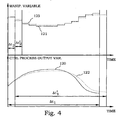
- the principles are illustrated in Fig. 4. With this approach, the entire optimization is performed over the prediction time interval ⁇ t 1 , represented by a controlled process output variable reference trajectory 120. However, only a first small portion of the input trajectories 121 (of which one is illustrated in the figure) is used for control purposes. This time portion is in the present disclosure called the control time interval ⁇ t 2 .
- the control time interval is preferably substantially shorter than the prediction time interval and may e.g. be equal to the sampling time mentioned earlier. Typically, the control time interval is more than ten times shorter than the prediction time interval.
- a new optimisation is performed, resulting in new state variable trajectories 122 and new input trajectories 123.
- the control operation can hence be performed during the new control time interval ⁇ t 2 *.
- the procedure can continue by successively move the prediction time interval and the control time interval forward. In this way, the accuracy is guaranteed at the same time as an optimum time dependence of the optimization horizon is ensured.
- a previous input trajectory is believed to form a very advantageous start approximation for the following optimization.
- the start point or the initial state of the process is used.
- This initial state is estimated by using the model and present and preferably also previous measurements of different quantities associated with process output variables. Since both the model and the measurements suffer from noise and uncertainties, a preferred embodiment of the present invention employs some kind of state estimation procedure.
- R and Q are the covariance matrix of measurement deviation uncertainty and uncertainty of the model, respectively, giving a weighting between the uncertainty of measurements and model, respectively.
- FIG. 6 An approach to implement state estimation is to use a moving horizon estimation. This is schematically illustrated in Fig. 6.
- a diagram illustrates a series of measurements 130 of a process output variable at different sampling times.
- a frame 131 defines a certain number of previous measurements, which are going to be used in the state estimation process. The previous measurements are put into the dynamic process model and minimized regarding the measurement noise and the model uncertainty. From the optimization using measurements from the entire frame 131, an estimated value 132 based on the present measured value is provided, which is believed to resemble the actual value 133 in a better manner. The estimation is thus performed using the dynamic process model in a historical perspective. The following optimization of the control procedure uses the same fundamental dynamic process model in a future perspective instead.
- the actual state estimation can also be performed using other techniques, e.g. Kalman filter techniques. Different state estimations may be optimal for different process systems, depending on the actual design of the process model.
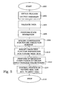
- step 200 process output variables are obtained.
- step 204 this data is validated and in step 206 a state estimation is performed in order to determine an initial state.
- Constraints for a future prediction horizon ⁇ t 1 are specified in step 208.
- a production plan for the prediction horizon interval is provided.
- objective function parameters are specified for the future prediction horizon. This objective function depends on predicted controlled process output variables.
- the method is applied on pulp and paper production, where at least one controlled process output variable is associated with the amount, distribution and/or consumption of chemical additives.
- step 212 input trajectories for manipulated variables for the prediction time interval are created by an optimization process.
- the input trajectories correspond to those manipulated variables that optimize the objective function, under the constraints.
- the process is controlled in step 214 by setting the manipulated variables according to the input trajectories during a control time interval ⁇ t 2 .
- the process ends in step 216.
- the steps of the present flow diagram are repeated.
- the state estimation step 206, and the optimization computation 212 are performed using a dynamic process model.
- the dynamic process model has time dependent relations between manipulated variables of process sections of the process and process output variables of the same process section.
- a computer program product implementing the method or a part thereof comprises software or a computer program run on a general purpose or specially adapted computer, processor or microprocessor.
- the software includes computer program code elements or software code portions that make the computer perform the method using at least one of the steps previously described in Fig. 5.
- the program may be stored in whole or part, on, or in, one or more suitable computer readable media or data storage means such as a magnetic disk, CD-ROM or DVD disk, hard disk, magneto-optical memory storage means, in RAM or volatile memory, in ROM or flash memory, as firmware, or on a data server.
- Such a computer program product can also be supplied via a network, such as Internet.
- FIG. 7 an embodiment of a pulp and paper process system 2 according to the present invention is illustrated schematically.
- the illustrated process system 2 is based on the sulfate process principle.
- an initial input flow consists of wood chips 82A.
- a flow of wood chips 80A enters a digester 60A, where the chips are cooked at approximately 170°C with a liquor, called white liquor 80P, containing OH- and HS- ions as active species. Lignin is then separated from the carbohydrates, cellulose and hemicellulose in the fibers.
- the cooking can be done in either a continuous or a batch process. After the cooking, the pulp is washed (not shown in the figure) and provided as a flow 80B.
- Pulp 80C is further delignified in an oxygen delignification stage 60B. After oxygen delignification, pulp 80D, 80E is transported to a bleach plant 60C. Bleached pulp 80F, 80G is supplied to a paper machine 60D for the actual papermaking process step. Paper 84A leaves the plant as the output product.
- Liquor spent from the cooking 60A containing the cooking chemicals and the dissolved organic substance is called weak black liquor 80H.
- the black liquor 80I is brought to and evaporated in the evaporation plant 60E from a dry solid content from below 20% to 65-80% dry solid content.
- the evaporated black liquor is provided to a recovery boiler 60F, where it is combusted. In the combustion, the energy of the organic substance is recovered in the form of high-pressure steam.
- the inorganic substance is separated as a smelt at the bottom of the boiler.
- the sulfur compounds are here reduced to sulfide (S 2- ).
- the smelt consists mainly of sodium carbonate and sodium sulfide.
- the smelt is dissolved in water and the resulting liquor 80L is called green liquor.
- the sulfide is hydrolyzed to OH - and HS - when it is brought into contact with the water.
- the green liquor 80M is provided to a recausticizing department 60H.
- the carbonate is transformed to OH - - ions by the reaction with Ca(OH) 2 .
- the solid calcium carbonate that is used is burned to CaO in a lime kiln 60I and thereafter slaked to give Ca(OH) 2 represented by 80S, which is entered via 80T into the recausticizing department 60H.
- the slurry 80N is filtrated in filter 60G to give white liquor 800, the rest 80Q is returned as an input 80R to the lime kiln 60I.
- the white liquor 80P is returned to the digester 60A.
- Make-up chemicals are added, such as NaOH in 82B and Na2SO 4 in 82C to replace losses and to adjust sodium and sulfur imbalances.
- ESP-dust 84B (ElectroStatic Precipitator) from the recovery boiler 60F.
- ESP-dust 84B consists mainly of Na 2 SO 4 and some Na 2 CO 3 .
- the balance between sodium and sulfur is defined by the sulfidity of the white liquor. If the sulfidity is above the set point, sulfur has to be purged by ESP-dust. Since the ESP-dust also contains sodium, sodium will be lost. This loss has to be covered with NaOH make-up. If the sulfidity is below the target, sulfur has to be added to the process (for example as Na 2 SO 4 in 82C).
- Wood chips are stored in 70A. Pulp of different quality is stored in 70B-D. Weak black liquor is stored in 70E, prior to evaporation. Strong black liquor 80J with a high dry-solid content is stored in 70F.
- Tank 70G contains green liquor and 70H contains white liquor.
- lime mud mainly CaCO 3
- the burned lime mainly CaO
- EA effective alkali
- degree of caustization degree of caustization
- sulfidity degree of caustization
- Flow rates represented by 57
- a number of optimizing aspects are used.
- One goal for the optimization according to the present invention is to minimize the discrepancy of certain concentrations of chemical species with regard to recommended set-point values.
- the sulfidity of the white liquor 80P provided to the digester 60A is important to control to keep the sulfidity of the digester 60A as constant as possible close to a desired level. It is thus preferred to select the sulfidity in the digester 60A as one of the controlled process output variables. It is also desirable to keep the total cost for chemicals down, and therefore the additions 82B and 82C should be kept as low as possible, as well as the outlet ESP-dust flow 84B.
- the flows 82B, 82C and 84B also should be selected as controlled process output variables.
- optimization to minimize production losses at minor production disturbances and to minimize the effects of bottleneck processes are typically based on controlled process output variables in the form of buffer levels of buffer tanks before and after identified problem sections.
- Optimizing criteria such as keeping the production rate according to the production plan, to minimize the variations in fiber need at the paper machine 60D etc. are also included as terms in the objective function.
- the described method is preferably implemented, as illustrated in Fig. 8 by a suitable network topology, in a separate server connected to an internal mill computer network 13.
- the network will typically be connected to a domain server 12.
- a server 14 where the method is implemented will typically also include functionality to exchange data with the process control system and other servers 15 containing relevant data as e.g. process history data storage systems, laboratory data storage systems 3 etc.
- a preferable way to exchange data is via OPC (Object Linking and Embedding for Process Control) 4.
- OPC is a specification requiring all data sources to show the same type of interface.
- OPC is a well-known specification published by the OPC foundation. It is based on Microsoft's Component Object Model (COM).
- COM Component Object Model
- the server 14 could e.g. use the Aspect Integration Platform (AIP-server) as the communication layer between the described method and the mill information.
- AIP-server Aspect Integration Platform
- This approach makes it possible to access the server 14 via separate workplaces 5, which in case of the Aspect Integration Platform is used could be clients including Operate IT.
- the internal mill computer network is often connected to an intranet 6 via a router 7. This makes it possible to access the described method via workplaces with thin clients 8, using Internet Explorer. Via a firewall 9, the described method could also be accessed via computers connected to the Internet 11.
- a system with Internet connection does as an alternative also allow for the method to be implemented in a server at a remote location. The service provider at this remote location will then have a similar network topology as the mill network, as indicated in Fig.
- the server 14 at the mill network 13 is in this case not needed.
- the described method will in this case be installed in an equivalent server (14b) at the remote network.
- This remote location may be at a service provider's office. From this remote location several client mills may simultaneously be optimised and controlled in real time by using the described method.
- the present invention is described by examples from pulp and paper industry, and in particular connected to optimization of the use of chemical additives. These examples are especially well suited for applying the present invention. However, also other optimization considerations may be used with the present invention.
- the invention can also be applied to other process production systems with process sections and/or intermediate storages in, for example the chemical industry, the petrochemical industry (refineries etc.), pharmaceutical and food industry, consumer industry and metal and minerals industry.
Landscapes
- Engineering & Computer Science (AREA)
- Software Systems (AREA)
- Artificial Intelligence (AREA)
- Computer Vision & Pattern Recognition (AREA)
- Evolutionary Computation (AREA)
- Medical Informatics (AREA)
- Health & Medical Sciences (AREA)
- Physics & Mathematics (AREA)
- General Physics & Mathematics (AREA)
- Automation & Control Theory (AREA)
- Feedback Control In General (AREA)
- Paper (AREA)
- Management, Administration, Business Operations System, And Electronic Commerce (AREA)
- General Factory Administration (AREA)
- Amplifiers (AREA)
Claims (42)
- Verfahren für einen Produktionsprozess (1) mit einer Anzahl von Prozessabschnitten (10A-D; 60A-I), umfassend die Schritte:- Erhalten eines dynamischen Prozessmodells mit Beziehungen zwischen manipulierten Variablen und Prozessausgabevariablen;- Bereitstellen externer Bedingungen für den Produktionsprozess (1);- Messen eines Satzes von Prozessausgabevariablen des Produktionsprozesses (1);- Definieren einer Zielfunktion;- Optimieren der Zielfunktion; und- Ausführen des Produktionsprozesses (1) durch Einstellen der manipulierten Variablen;dadurch gekennzeichnet, dass- das dynamische Prozessmodell zeitabhängige Beziehungen zwischen manipulierten Variablen für die Prozessabschnitte (10A-D; 60A-I) und Prozessausgabevariablen von dem jeweiligen Prozessabschnitt (10A-D; 60A-I) einschließt;- ein anfänglicher Zustand (115) unter Verwendung der gemessenen Prozessausgabevariablen abgeschätzt wird;- die externen Bedingungen für den Produktionsprozess (1) für ein Vorhersage-Zeitintervall (Δt1) bereitgestellt werden;- die Zielfunktion vorhergesagte gesteuerte Prozessausgabevariablen für das Vorhersage-Zeitintervall (Δt1) und die externen Bedingungen beinhaltet;- die vorhergesagten gesteuerten Prozessausgabevariablen durch das dynamische Prozessmodell basierend auf dem anfänglichen Zustand (115) definiert werden;- die Zielfunktion unter Bedingungen optimiert wird, die durch das dynamische Prozessmodell und/oder die externen Bedingungen auferlegt werden, durch Anpassen der manipulierten Variablen, so dass sich Eingangs-Trajektorien für die manipulierten Variablen für das Vorhersage-Zeitintervall (Δt1) ergeben;- der Produktionsprozessprozess (1) durch Einstellen der manipulierten Variablen gemäß den Eingangs-Trajektorien während eines Steuerzeitintervalls (Δt2) durchgeführt wird;- wobei das Steuerzeitintervall (Δt2) ein Teil des Vorhersage-Zeitintervalls (△t1) ist.
- Verfahren nach Anspruch 1, dadurch gekennzeichnet, dass das Verfahren ein Pulpe- und/oder Papier-Produktionsverfahren ist.
- Verfahren nach Anspruch 2, dadurch gekennzeichnet, dass die gesteuerten Prozessausgabevariablen mindestens eine Variable umfassen, die mit chemischen Additiven verknüpft ist, die für die Pulpe- und/oder Papier-Produktion verwendet werden.
- Verfahren nach Anspruch 3, dadurch gekennzeichnet, dass der Schritt des Definierens wiederum den Schritt umfasst, einen Zielfunktions-Term einzuschließen, der von einem Gesamtmaß an chemischen Additiven in mindestens zweien der Prozessabschnitte abhängt.
- Verfahren nach Anspruch 3 oder 4, dadurch gekennzeichnet, dass der Schritt des Definierens wiederum den Schritt umfasst, einen Zielfunktions-Term einzuschließen, der von der relativen Verteilung verschiedener chemischer Formen chemischer Additive zwischen verschiedenen Prozessabschnitten (10A-D; 60A-I) in dem Produktionsprozess abhängt.
- Verfahren nach irgendeinem der Ansprüche 3 bis 5, dadurch gekennzeichnet, dass der Schritt des Definierens wiederum den Schritt umfasst, einen Zielfunktions-Term einzuschließen, der von einer Differenz zwischen einer Konzentration von mindestens einem chemischen Additiv in mindestens einem der Prozessabschnitte (10A-D; 60A-I) und einem vorbestimmten Einstellwert abhängt.
- Verfahren nach Anspruch 6, dadurch gekennzeichnet, dass die Konzentration sich auf die Sulfidität bezieht.
- Verfahren nach irgendeinem der Ansprüche 1 bis 7, dadurch gekennzeichnet, dass die externen Bedingungen einen Produktionsplan (110, 111) umfassen.
- Verfahren nach irgendeinem der Ansprüche 1 bis 8, dadurch gekennzeichnet, dass die Abschätzung des anfänglichen Zustands (115) auch durch vorher gemessene Prozessausgabevariablen erhalten wird.
- Verfahren nach Anspruch 9, dadurch gekennzeichnet, dass die Abschätzung des anfänglichen Zustands einen Zustandabschätzungs-Vorgang umfasst.
- Verfahren nach Anspruch 10, dadurch gekennzeichnet, dass der Zustandabschätzungs-Vorgang eine Moving-Horizon-Zustandsabschätzung ist.
- Verfahren nach irgendeinem der Ansprüche 1 bis 11, dadurch gekennzeichnet, dass das Steuerzeitintervall (Δt2) wesentlich kürzer ist als das Vorhersage-Zeitintervall (Δt1).
- Verfahren nach Anspruch 12, dadurch gekennzeichnet, dass das Vorhersage-Zeitintervall (Δt1) mehr als 10 Mal länger ist als das Steuerzeitintervall (Δt2).
- Verfahren nach irgendeinem der Ansprüche 1 bis 13, dadurch gekennzeichnet, dass mindestens ein Teil des Messens von Prozessausgabevariablen online ausgeführt wird.
- Verfahren nach irgendeinem der Ansprüche 1 bis 14, dadurch gekennzeichnet, dass mindestens eine der Prozessausgabevariablen ausgewählt ist aus der Liste:- Flussrate;- Flusskonzentration;- Pufferpegel;- Pufferkonzentration; und- interne Prozessabschnittsvariable.
- Verfahren nach irgendeinem der Ansprüche 1 bis 15, dadurch gekennzeichnet, dass der Schritt des Definierens wiederum den Schritt umfasst:- Ableiten von Ziel-Trajektorien (r(t)) für die gesteuerten Prozessausgabevariablen unter den externen Bedingungen, beginnend mit dem anfänglichen Zustand (115);wodurch die Zielfunktion Abweichungen zwischen den Ziel-Trajektorien (r(t)) und vorhergesagten Prozessausgabevariablen (116) umfasst, integriert über das Vorhersage-Zeitintervall (Δt1).
- Verfahren nach Anspruch 16, dadurch gekennzeichnet, dass der Schritt des Ableitens wiederum die Schritte umfasst:- Berechnen idealer Sollwert-Trajektorien (s(t)) für die gesteuerten Prozessausgabevariablen unter Bedingungen, die durch den Produktionsplan (110, 111) auferlegt werden; und- Modifizieren der idealen Sollwert-Trajektorien (s(t)) in die Ziel-Trajektorien (r(t)) durch Einführen des anfänglichen Zustands (115) und einer zeitbezogenen Glättung von Strukturen der idealen Sollwert-Trajektorien (s(t)).
- Verfahren nach Anspruch 16 oder 17, dadurch gekennzeichnet, dass die Integration über das Vorhersage-Zeitintervall (Δt1) weiter eine zeitabhängige Gewichtungsfunktion umfasst.
- Verfahren nach irgendeinem der Ansprüche 1 bis 18, dadurch gekennzeichnet, dass das dynamische Prozessmodell wiederum eine Anzahl von Abschnittsmodellen (10A-D; 60A-I) umfasst, welche die Ausführung eines Prozessabschnitts repräsentieren, verbunden mit einer Anzahl von Zwischen-Speichermodellen (20A-H; 70A-J) durch Modell-Flüsse (30A-M; 80A-T);- wobei die Abschnittsmodelle (10A-D; 60A-I) die zeitabhängigen Beziehungen umfassen; und- die Zwischen-Speichermodelle (20A-H; 70A-J) durch einen Pufferpegel gekennzeichnet sind.
- Verfahren nach Anspruch 19, dadurch gekennzeichnet, dass der Schritt des Definierens wiederum den Schritt umfasst, einen Zielfunktions-Term einzuschließen, der von der verbleibenden Pufferkapazität eines Puffers, der einem Engpass-Prozessabschnitt vorhergeht, und des Pufferpegels eines Puffers abhängig ist, der einem Engpass-Prozessabschnitt nachfolgt.
- Verfahren nach Anspruch 19 oder 20, dadurch gekennzeichnet, dass der Schritt des Definierens wiederum den Schritt umfasst, einen Zielfunktions-Term einzuschließen, der von dem Pufferpegel eines Puffers, der einem Prozessabschnitt vorhergeht, der eine relativ hohe Wahrscheinlichkeit des Versagens aufweist, und von einer verbleibenden Pufferkapazität eines Puffers abhängig ist, der einem Prozessabschnitt nachfolgt, der eine relativ hohe Wahrscheinlichkeit des Versagens aufweist.
- Verfahren nach irgendeinem der Ansprüche 1 bis 21, dadurch gekennzeichnet, dass einer oder mehrere Schritte des Verfahrens an einem Ort ausgeführt werden, der von dem Produktionsprozess entfernt liegt.
- System für einen Produktionsprozess (1) mit einer Anzahl von Prozessabschnitten (10A-D; 60A-I), steuerbar durch manipulierte Variablen, umfassend:- Prozessormittel; und- Prozessabschnitts-Steuermittel, welche die manipulierten Variablen einstellen, wobei die Prozessabschnitts-Steuermittel mit dem Prozessormittel verbunden sind;wobei das Prozessormittel wiederum umfasst:- Sensoreingabemittel zum Empfangen eines Satzes von Prozessausgabevariablen des Produktionsprozesses (1);- Mittel zum Erhalten eines dynamischen Prozessmodells mit Beziehungen zwischen manipulierten Variablen und Prozessausgabevariablen;- Mittel zum Bereitstellen externer Bedingungen für den Produktionsprozess;- Mittel zum Definieren einer Zielfunktion;- Mittel zum Optimieren der Zielfunktion;dadurch gekennzeichnet, dass- das dynamische Prozessmodell durch die jeweiligen Mittel modelliert wird, einschließlich zeitabhängiger Beziehungen zwischen manipulierten Variablen für die Prozessabschnitte (10A-D; 60A-I) und Prozessausgabevariablen von dem jeweiligen Prozessabschnitt (10A-D; 60A-I);- das Prozessormittel weiter Mittel umfasst, um einen anfänglichen Zustand (115) unter Verwendung der gemessenen Prozessausgabevariablen abzuschätzen;- die externen Bedingungen von dem jeweiligen Mittel für ein Vorhersage-Zeitintervall (Δt1) bereitgestellt werden;- die Zielfunktion durch das jeweilige Mittel definiert wird, beinhaltend vorhergesagte gesteuerte Prozessausgabevariablen für das Vorhersage-Zeitintervall (Δt1) und die externen Bedingungen, wobei die vorhergesagten gesteuerten Prozessausgabevariablen durch das dynamische Prozessmodell basierend auf dem anfänglichen Zustand (115) definiert werden;- die Zielfunktion durch das jeweilige Mittel unter Bedingungen optimiert wird, die durch das dynamische Prozessmodell und/oder die externen Bedingungen auferlegt werden, durch Anpassen der manipulierten Variablen, so dass sich Eingangs-Trajektorien für die manipulierten Variablen für das Vorhersage-Zeitintervall (Δt1) ergeben;- das Prozessabschnitts-Steuermittel eingerichtet ist zum Einstellen der manipulierten Variablen gemäß der Eingangs-Trajektorien während eines Steuerzeitintervalls (Δt2), wobei das Steuerzeitintervall (Δt2) ein Teil des Vorhersage-Zeitintervalls (Δt1) ist.
- System nach Anspruch 23, dadurch gekennzeichnet, dass der Produktionsprozess (1) ein Pulpe- und/oder Papier-Produktionsprozess ist.
- System nach Anspruch 24, dadurch gekennzeichnet, dass die gesteuerten Prozessausgabevariablen mindestens eine Variable umfassen, die mit chemischen Additiven des Produktionsprozesses (1) verknüpft ist.
- System nach Anspruch 25, dadurch gekennzeichnet, dass die Zielfunktion einen Term einschließt, der von einem Gesamtmaß an chemischen Additiven in mindestens zweien der Prozessabschnitte des Produktionsprozesses (1) abhängt.
- System nach Anspruch 25 oder 26, dadurch gekennzeichnet, dass die Zielfunktion Beziehungen einschließt, die auf der relativen Verteilung verschiedener chemischer Arten chemischer Additive zwischen verschiedenen Prozessabschnitten (10A-D; 60A-I) in dem Produktionsprozess (1) basieren.
- System nach irgendeinem der Ansprüche 25 bis 27, dadurch gekennzeichnet, dass die Zielfunktion einen Term einschließt, der von einer Differenz zwischen einer Konzentration von mindestens einem chemischen Additiv in mindestens einem der Prozessabschnitte (10A-D; 60A-I) und einem vorbestimmten Einstellwert abhängt.
- System nach Anspruch 28, dadurch gekennzeichnet, dass die Konzentration sich auf die Sulfidität bezieht.
- System nach irgendeinem der Ansprüche 23 bis 29, dadurch gekennzeichnet, dass die externen Bedingungen einen Produktionsplan (110, 111) umfassen.
- System nach irgendeinem der Ansprüche 23 bis 30, dadurch gekennzeichnet, dass die Abschätzung des anfänglichen Zustands (115) auch durch vorhergehend gemessene Prozessausgabevariablen erhalten wird.
- System nach Anspruch 31, dadurch gekennzeichnet, dass das Prozessormittel weiter Zustandsabschätzungsmittel umfasst, um die Abschätzung des anfänglichen Zustands (115) auszuführen.
- System nach irgendeinem der Ansprüche 23 bis 32, dadurch gekennzeichnet, dass mindestens eine der Prozessausgabevariablen des Produktionsprozesses (1) eine Zeitkonstante aufweist, die 12 Stunden übersteigt.
- System nach irgendeinem der Ansprüche 23 bis 33, dadurch gekennzeichnet, dass das Vorhersage-Zeitintervall (Δt1) 12 Stunden übersteigt.
- System nach irgendeinem der Ansprüche 23 bis 34, dadurch gekennzeichnet, dass das Steuerzeitintervall (Δt2) kleiner als 15 Minuten ist.
- System nach irgendeinem der Ansprüche 23 bis 35, gekennzeichnet durch Kommunikationsverbindungen zwischen dem Prozessor und dem Produktionsprozess, um eine Fernsteuerung des Produktionsprozesses zu ermöglichen.
- System nach Anspruch 36, dadurch gekennzeichnet, dass die Kommunikationsverbindungen ein Datenkommunikationsnetzwerk umfassen.
- Computerprogrammprodukt, eingerichtet, um einen Prozessor dazu zu bringen, ein Verfahren nach irgendeinem der Ansprüche 1 bis 22 auszuführen.
- Verwendung eines Verfahrens nach irgendeinem der Ansprüche 1 bis 22, um in einen Produktionsprozess irgendeinen der folgenden Vorgänge auszuführen:Überwachen, Steuern, Regulieren, Simulieren, Optimieren, Unterstützung für Entscheidungen bereitstellen, Hinweisen.
- Verwendung eines Verfahrens nach irgendeinem der Ansprüche 1 bis 22, um in einen Pulpe- und/oder Papier-Produktionsprozess irgendeinen der folgenden Vorgänge auszuführen:Überwachen, Steuern, Regulieren, Simulieren, Optimieren, Unterstützung für Entscheidungen bereitstellen, Hinweisen.
- Verwendung eines Systems nach irgendeinem der Ansprüche 23 bis 37, um in einen Produktionsprozess irgendeinen der folgenden Vorgänge auszuführen:Überwachen, Steuern, Regulieren, Simulieren, Optimieren, Unterstützung für Entscheidungen bereitstellen, Hinweisen.
- Verwendung eines Systems nach irgendeinem der Ansprüche 23 bis 37, um in einen Pulpe- und/oder Papier-Produktionsprozess irgendeinen der folgenden Vorgänge auszuführen:Überwachen, Steuern, Regulieren, Simulieren, Optimieren, Unterstützung für Entscheidungen bereitstellen, Hinweisen.
Applications Claiming Priority (3)
| Application Number | Priority Date | Filing Date | Title |
|---|---|---|---|
| SE0201812A SE522691C3 (sv) | 2002-06-12 | 2002-06-12 | Dynamisk on-line-optimering av produktionsprocesser |
| SE0201812 | 2002-06-12 | ||
| PCT/SE2003/000991 WO2003107103A1 (en) | 2002-06-12 | 2003-06-12 | Dynamic on-line optimization of production processes |
Publications (2)
| Publication Number | Publication Date |
|---|---|
| EP1520215A1 EP1520215A1 (de) | 2005-04-06 |
| EP1520215B1 true EP1520215B1 (de) | 2007-09-26 |
Family
ID=20288179
Family Applications (1)
| Application Number | Title | Priority Date | Filing Date |
|---|---|---|---|
| EP03736394A Expired - Lifetime EP1520215B1 (de) | 2002-06-12 | 2003-06-12 | Dynamische online-optimierung von produktionsprozessen |
Country Status (13)
| Country | Link |
|---|---|
| US (1) | US7085615B2 (de) |
| EP (1) | EP1520215B1 (de) |
| CN (1) | CN1675599A (de) |
| AT (1) | ATE374390T1 (de) |
| AU (1) | AU2003237734A1 (de) |
| BR (1) | BR0311766A (de) |
| CA (1) | CA2489025C (de) |
| DE (1) | DE60316567T2 (de) |
| ES (1) | ES2294298T3 (de) |
| NO (1) | NO334123B1 (de) |
| PT (1) | PT1520215E (de) |
| SE (1) | SE522691C3 (de) |
| WO (1) | WO2003107103A1 (de) |
Cited By (1)
| Publication number | Priority date | Publication date | Assignee | Title |
|---|---|---|---|---|
| EP3506029A1 (de) | 2017-12-28 | 2019-07-03 | ABB Schweiz AG | Verfahren und steuerungssystem zur steuerung eines echten herstellungsprozesses |
Families Citing this family (87)
| Publication number | Priority date | Publication date | Assignee | Title |
|---|---|---|---|---|
| US8914300B2 (en) | 2001-08-10 | 2014-12-16 | Rockwell Automation Technologies, Inc. | System and method for dynamic multi-objective optimization of machine selection, integration and utilization |
| US20090204237A1 (en) * | 2001-08-10 | 2009-08-13 | Rockwell Automation Technologies, Inc. | System and method for dynamic multi-objective optimization of machine selection, integration and utilization |
| US20090210081A1 (en) * | 2001-08-10 | 2009-08-20 | Rockwell Automation Technologies, Inc. | System and method for dynamic multi-objective optimization of machine selection, integration and utilization |
| US9729639B2 (en) * | 2001-08-10 | 2017-08-08 | Rockwell Automation Technologies, Inc. | System and method for dynamic multi-objective optimization of machine selection, integration and utilization |
| US7797062B2 (en) * | 2001-08-10 | 2010-09-14 | Rockwell Automation Technologies, Inc. | System and method for dynamic multi-objective optimization of machine selection, integration and utilization |
| US8417360B2 (en) * | 2001-08-10 | 2013-04-09 | Rockwell Automation Technologies, Inc. | System and method for dynamic multi-objective optimization of machine selection, integration and utilization |
| EP1548621A1 (de) * | 2003-12-19 | 2005-06-29 | Sap Ag | Schnittstelle zum Verändern von Rezepten |
| US20080281438A1 (en) * | 2004-04-23 | 2008-11-13 | Model Predictive Systems, Inc. | Critical dimension estimation |
| DE102004025574B4 (de) * | 2004-05-25 | 2013-02-28 | Abb Research Ltd. | Verfahren zur Fehlererkennung in einem industriellen Prozess |
| FR2878353A1 (fr) * | 2004-11-24 | 2006-05-26 | Data Proc Conseil Sarl | Methode de detection de la position des goulets d'etranglement d'une chaine de montage d'objets complexes |
| US7467614B2 (en) | 2004-12-29 | 2008-12-23 | Honeywell International Inc. | Pedal position and/or pedal change rate for use in control of an engine |
| DE102005021337A1 (de) * | 2005-05-04 | 2006-11-16 | Abb Patent Gmbh | System und Verfahren zur korrigierenden Planung und Optimierung von Verarbeitungsprozessen |
| EP1917619B1 (de) * | 2005-07-27 | 2016-08-17 | Exxonmobil Upstream Research Company | Mit der extraktion von kohlenwasserstoffen aus unteroberflächenformationen assoziierte bohrlochmodellierung |
| US7389773B2 (en) | 2005-08-18 | 2008-06-24 | Honeywell International Inc. | Emissions sensors for fuel control in engines |
| US7840287B2 (en) * | 2006-04-13 | 2010-11-23 | Fisher-Rosemount Systems, Inc. | Robust process model identification in model based control techniques |
| GB0613955D0 (en) * | 2006-07-13 | 2007-01-10 | Bae Systems Plc | Controller |
| DE102006045509A1 (de) * | 2006-09-15 | 2008-03-27 | Daimler Ag | Verfahren und Vorrichtung zur Produktionsplanung |
| PL1901142T3 (pl) * | 2006-09-18 | 2018-07-31 | Abb Research Ltd. | Optymalizacja procesu rozdzielania materiałów |
| EP2087433A4 (de) * | 2006-11-14 | 2017-11-29 | ABB, Inc. | System zum speichern und präsentieren von sensor- und spektraldaten für batch-prozesse |
| US7826909B2 (en) * | 2006-12-11 | 2010-11-02 | Fakhruddin T Attarwala | Dynamic model predictive control |
| US20080243570A1 (en) * | 2007-03-27 | 2008-10-02 | Jayan Moorkanat | Time-Based Decomposition for Optimization of Master Planning Problems |
| EP2158356A4 (de) * | 2007-05-04 | 2013-07-31 | Quebec Centre Rech Ind | System und verfahren zur optimierung der aufbereitung von teilchenförmigem lignocellulosischem material |
| US8489240B2 (en) * | 2007-08-03 | 2013-07-16 | General Electric Company | Control system for industrial water system and method for its use |
| US20090264225A1 (en) * | 2008-04-17 | 2009-10-22 | Lee William B | Golf tee |
| DE102008021556B4 (de) * | 2008-04-30 | 2019-06-06 | Advanced Micro Devices, Inc. | Verfahren und System für zweistufige Vorhersage einer Qualitätsverteilung von Halbleiterbauelementen |
| US8060290B2 (en) | 2008-07-17 | 2011-11-15 | Honeywell International Inc. | Configurable automotive controller |
| US8594828B2 (en) * | 2008-09-30 | 2013-11-26 | Rockwell Automation Technologies, Inc. | System and method for optimizing a paper manufacturing process |
| US8155932B2 (en) * | 2009-01-08 | 2012-04-10 | Jonas Berggren | Method and apparatus for creating a generalized response model for a sheet forming machine |
| WO2010128354A1 (en) | 2009-05-06 | 2010-11-11 | Abb Research Ltd | A method and a system for on-line optimization of a batch pulp digester |
| US9141911B2 (en) | 2009-05-29 | 2015-09-22 | Aspen Technology, Inc. | Apparatus and method for automated data selection in model identification and adaptation in multivariable process control |
| JP5734961B2 (ja) * | 2009-05-29 | 2015-06-17 | アスペン テクノロジー インコーポレイテッド | 多変数プロセス制御においてモデルの品質を推定しモデルを適応させる装置およびその方法 |
| US9760067B2 (en) | 2009-09-10 | 2017-09-12 | Honeywell International Inc. | System and method for predicting future disturbances in model predictive control applications |
| US8620461B2 (en) | 2009-09-24 | 2013-12-31 | Honeywell International, Inc. | Method and system for updating tuning parameters of a controller |
| CA2714235C (en) | 2010-04-27 | 2014-01-07 | Centre De Recherche Industrielle Du Quebec | Method and system for stabilizing dry-based density of wood chips to be fed to a chip refining process |
| US8504175B2 (en) * | 2010-06-02 | 2013-08-06 | Honeywell International Inc. | Using model predictive control to optimize variable trajectories and system control |
| US9677493B2 (en) | 2011-09-19 | 2017-06-13 | Honeywell Spol, S.R.O. | Coordinated engine and emissions control system |
| US9650934B2 (en) | 2011-11-04 | 2017-05-16 | Honeywell spol.s.r.o. | Engine and aftertreatment optimization system |
| US20130111905A1 (en) | 2011-11-04 | 2013-05-09 | Honeywell Spol. S.R.O. | Integrated optimization and control of an engine and aftertreatment system |
| EP2621074A1 (de) * | 2012-01-24 | 2013-07-31 | ABB Research Ltd. | Multicorefähige kostenfunktionsbasierte prädiktive Steuerungsmethode eines Umrichters |
| US9513610B2 (en) | 2012-02-08 | 2016-12-06 | Aspen Technology, Inc. | Apparatus and methods for non-invasive closed loop step testing using a tunable trade-off factor |
| CN103513618B (zh) * | 2012-06-18 | 2016-01-27 | 新奥科技发展有限公司 | 工业过程的控制方法和设备 |
| CN104583881B (zh) * | 2012-08-29 | 2017-05-24 | 丰田自动车株式会社 | 设备控制装置 |
| WO2014096507A1 (en) | 2012-12-21 | 2014-06-26 | Metso Automation Oy | Controller and method for controlling a property of an object |
| FI125364B (en) * | 2013-04-19 | 2015-09-15 | Metso Automation Oy | Process optimization |
| DE102013224700A1 (de) * | 2013-12-03 | 2015-06-03 | Siemens Aktiengesellschaft | Vorrichtung und Verfahren zur Änderung von Betriebseinstellungen einer technischen Anlage |
| BR112016019527B1 (pt) * | 2014-02-26 | 2022-08-16 | Abb Schweiz Ag | Sistema para a otimização de uma operação de digestor contínuo de um digestor contínuo e método para otimizar uma operação de digestor contínuo de um digestor contínuo usando um ou mais processadores |
| JP5949827B2 (ja) * | 2014-04-15 | 2016-07-13 | 横河電機株式会社 | エネルギー管理システム |
| CN104155958A (zh) * | 2014-08-25 | 2014-11-19 | 理程自动化技术(天津)有限公司 | 化学机械浆工艺的优化控制系统 |
| CN104317270B (zh) * | 2014-11-04 | 2017-05-24 | 中国轻工业南宁设计工程有限公司 | 一种苛化自动控制系统 |
| EP3051367B1 (de) | 2015-01-28 | 2020-11-25 | Honeywell spol s.r.o. | Ansatz und system zur handhabung von einschränkungen für gemessene störungen mit unsicherer vorschau |
| EP3056706A1 (de) | 2015-02-16 | 2016-08-17 | Honeywell International Inc. | Ansatz zur nachbehandlungssystemmodellierung und modellidentifizierung |
| EP3091212A1 (de) | 2015-05-06 | 2016-11-09 | Honeywell International Inc. | Identifikationsansatz für verbrennungsmotor-mittelwertmodelle |
| WO2016196762A1 (en) * | 2015-06-05 | 2016-12-08 | Shell Oil Company | System and method for handling equipment service for model predictive controllers and estimators |
| EP3125052B1 (de) | 2015-07-31 | 2020-09-02 | Garrett Transportation I Inc. | Quadratischer programmlöser für mpc mit variabler anordnung |
| US10272779B2 (en) | 2015-08-05 | 2019-04-30 | Garrett Transportation I Inc. | System and approach for dynamic vehicle speed optimization |
| US10415492B2 (en) | 2016-01-29 | 2019-09-17 | Garrett Transportation I Inc. | Engine system with inferential sensor |
| US10036338B2 (en) | 2016-04-26 | 2018-07-31 | Honeywell International Inc. | Condition-based powertrain control system |
| US10124750B2 (en) | 2016-04-26 | 2018-11-13 | Honeywell International Inc. | Vehicle security module system |
| US11264121B2 (en) * | 2016-08-23 | 2022-03-01 | Accenture Global Solutions Limited | Real-time industrial plant production prediction and operation optimization |
| EP3548729B1 (de) | 2016-11-29 | 2023-02-22 | Garrett Transportation I Inc. | Inferenzflusssensor |
| US11238547B2 (en) * | 2017-01-12 | 2022-02-01 | Johnson Controls Tyco IP Holdings LLP | Building energy cost optimization system with asset sizing |
| US12597772B2 (en) | 2017-06-07 | 2026-04-07 | Tyco Fire & Security Gmbh | Central plant control system with asset allocation override |
| EP3457513A1 (de) | 2017-09-13 | 2019-03-20 | Johnson Controls Technology Company | Gebäude-energiesystem mit lastverteilung |
| US11057213B2 (en) | 2017-10-13 | 2021-07-06 | Garrett Transportation I, Inc. | Authentication system for electronic control unit on a bus |
| US20190180210A1 (en) * | 2017-12-11 | 2019-06-13 | Evonik Industries Ag | Dynamic chemical network system and method accounting for interrelated global processing variables |
| NL2021726B1 (en) | 2018-09-28 | 2020-05-07 | Milgro Groep B V | Method of recircling |
| US11934159B2 (en) | 2018-10-30 | 2024-03-19 | Aspentech Corporation | Apparatus and methods for non-invasive closed loop step testing with controllable optimization relaxation |
| US11853032B2 (en) | 2019-05-09 | 2023-12-26 | Aspentech Corporation | Combining machine learning with domain knowledge and first principles for modeling in the process industries |
| US11782401B2 (en) | 2019-08-02 | 2023-10-10 | Aspentech Corporation | Apparatus and methods to build deep learning controller using non-invasive closed loop exploration |
| CN110632902B (zh) | 2019-09-06 | 2021-03-02 | 北京北方华创微电子装备有限公司 | 物料加工路径选择方法及装置 |
| WO2021076760A1 (en) | 2019-10-18 | 2021-04-22 | Aspen Technology, Inc. | System and methods for automated model development from plant historical data for advanced process control |
| MX2022005896A (es) * | 2019-11-14 | 2022-06-14 | Buckman Laboratories Int Inc | Sistema y metodo de control predictivo para el tratamiento de lavado de pasta marron en plantas de celulosa. |
| CN115136079A (zh) * | 2020-02-20 | 2022-09-30 | 赢创运营有限公司 | 用于过程控制的方法和系统 |
| US11676039B2 (en) | 2020-02-21 | 2023-06-13 | International Business Machines Corporation | Optimal interpretable decision trees using integer linear programming techniques |
| WO2021205479A2 (en) * | 2020-04-09 | 2021-10-14 | Tata Consultancy Services Limited | Method and system for real time trajectory optimization |
| EP4208870A4 (de) | 2020-09-04 | 2024-11-06 | Buckman Laboratories International, Inc. | Prädiktive systeme und verfahren für proaktive interventionen in chemischen prozessen |
| US12462900B2 (en) * | 2020-11-30 | 2025-11-04 | Insilico Medicine Ip Limited | Retrosynthesis systems and methods |
| US11630446B2 (en) | 2021-02-16 | 2023-04-18 | Aspentech Corporation | Reluctant first principles models |
| KR20220164246A (ko) * | 2021-06-04 | 2022-12-13 | 한국과학기술원 | 화학물질의 제형 자동화 장치 및 그 방법 |
| US12541191B2 (en) * | 2021-08-27 | 2026-02-03 | Samsung Electronics Co., Ltd. | Method and apparatus for optimizing synthetic conditions for generation of target products |
| US12164270B2 (en) * | 2021-10-19 | 2024-12-10 | International Business Machines Corporation | Process optimization with joint-level inflow model |
| CN114326588B (zh) * | 2022-03-14 | 2022-05-20 | 深圳市山龙智控有限公司 | 一种伺服驱动系统的效率优化控制方法、系统及存储介质 |
| JP7831064B2 (ja) * | 2022-03-25 | 2026-03-17 | セイコーエプソン株式会社 | シート製造システム |
| JP2023147685A (ja) * | 2022-03-30 | 2023-10-13 | セイコーエプソン株式会社 | シート製造システム |
| JP7848557B2 (ja) * | 2022-03-30 | 2026-04-21 | セイコーエプソン株式会社 | シート製造装置 |
| WO2025117947A1 (en) * | 2023-11-30 | 2025-06-05 | Buckman Laboratories International, Inc. | Predictive and real time process intervention involving a multicomponent defoamer feed unit |
| JP2026018879A (ja) * | 2024-07-25 | 2026-02-05 | 栗田工業株式会社 | 情報処理システム、情報処理方法及びプログラム |
Family Cites Families (16)
| Publication number | Priority date | Publication date | Assignee | Title |
|---|---|---|---|---|
| US5659667A (en) * | 1995-01-17 | 1997-08-19 | The Regents Of The University Of California Office Of Technology Transfer | Adaptive model predictive process control using neural networks |
| US5825653A (en) | 1997-03-14 | 1998-10-20 | Valmet Corporation | Method for overall regulation of a former of a paper machine or equivalent |
| US5933345A (en) | 1996-05-06 | 1999-08-03 | Pavilion Technologies, Inc. | Method and apparatus for dynamic and steady state modeling over a desired path between two end points |
| US6122555A (en) | 1997-05-05 | 2000-09-19 | Honeywell International Inc. | System and methods for globally optimizing a process facility |
| US6055483A (en) | 1997-05-05 | 2000-04-25 | Honeywell, Inc. | Systems and methods using bridge models to globally optimize a process facility |
| US6453308B1 (en) * | 1997-10-01 | 2002-09-17 | Aspen Technology, Inc. | Non-linear dynamic predictive device |
| GB9722514D0 (en) * | 1997-10-25 | 1997-12-24 | Arjo Wiggins Fine Papers Ltd | Production of patterned paper |
| FI974328L (fi) | 1997-11-25 | 1999-05-26 | Valmet Automation Inc | Menetelmä ja laitteisto paperin ominaisuuksien säätämiseksi |
| FI974327L (fi) | 1997-11-25 | 1999-05-26 | Valmet Automation Inc | Menetelmä ja laitteisto paperin ominaisuuksien säätämiseksi |
| FI982625L (fi) * | 1998-12-04 | 2000-06-05 | Valmet Automation Inc | Menetelmä ja laitteisto paperin ominaisuuksien säätämiseksi |
| US6347254B1 (en) * | 1998-12-31 | 2002-02-12 | Honeywell Inc | Process facility control systems using an efficient prediction form and methods of operating the same |
| DE19910910A1 (de) | 1999-03-11 | 2000-09-28 | Voith Sulzer Papiertech Patent | Verfahren zur Durchführung eines optimierten Faser- oder Papierherstellungsprozesses |
| US6826521B1 (en) * | 2000-04-06 | 2004-11-30 | Abb Automation Inc. | System and methodology and adaptive, linear model predictive control based on rigorous, nonlinear process model |
| CA2356470A1 (en) | 2000-09-15 | 2002-03-15 | General Electric Company | Method and system for optimizing mill operation |
| US6901300B2 (en) * | 2002-02-07 | 2005-05-31 | Fisher-Rosemount Systems, Inc.. | Adaptation of advanced process control blocks in response to variable process delay |
| FI111173B (fi) * | 2002-05-03 | 2003-06-13 | Metso Paper Inc | Menetelmä paperirainan laadun hallitsemiseksi |
-
2002
- 2002-06-12 SE SE0201812A patent/SE522691C3/sv not_active IP Right Cessation
-
2003
- 2003-06-12 US US10/487,099 patent/US7085615B2/en not_active Expired - Lifetime
- 2003-06-12 BR BR0311766-9A patent/BR0311766A/pt not_active Application Discontinuation
- 2003-06-12 DE DE60316567T patent/DE60316567T2/de not_active Expired - Fee Related
- 2003-06-12 WO PCT/SE2003/000991 patent/WO2003107103A1/en not_active Ceased
- 2003-06-12 EP EP03736394A patent/EP1520215B1/de not_active Expired - Lifetime
- 2003-06-12 CA CA2489025A patent/CA2489025C/en not_active Expired - Lifetime
- 2003-06-12 AU AU2003237734A patent/AU2003237734A1/en not_active Abandoned
- 2003-06-12 PT PT03736394T patent/PT1520215E/pt unknown
- 2003-06-12 CN CNA038189186A patent/CN1675599A/zh active Pending
- 2003-06-12 AT AT03736394T patent/ATE374390T1/de not_active IP Right Cessation
- 2003-06-12 ES ES03736394T patent/ES2294298T3/es not_active Expired - Lifetime
-
2005
- 2005-01-11 NO NO20050150A patent/NO334123B1/no not_active IP Right Cessation
Cited By (3)
| Publication number | Priority date | Publication date | Assignee | Title |
|---|---|---|---|---|
| EP3506029A1 (de) | 2017-12-28 | 2019-07-03 | ABB Schweiz AG | Verfahren und steuerungssystem zur steuerung eines echten herstellungsprozesses |
| WO2019129549A1 (en) | 2017-12-28 | 2019-07-04 | Abb Schweiz Ag | Method and control system for controlling a real production process |
| US11543813B2 (en) | 2017-12-28 | 2023-01-03 | Abb Schweiz Ag | Method and control system for controlling a real production process |
Also Published As
| Publication number | Publication date |
|---|---|
| US7085615B2 (en) | 2006-08-01 |
| NO20050150D0 (no) | 2005-01-11 |
| CA2489025C (en) | 2014-12-30 |
| SE0201812L (sv) | 2003-12-13 |
| SE0201812D0 (sv) | 2002-06-12 |
| SE522691C2 (sv) | 2004-03-02 |
| ES2294298T3 (es) | 2008-04-01 |
| ATE374390T1 (de) | 2007-10-15 |
| BR0311766A (pt) | 2005-06-07 |
| SE522691C3 (sv) | 2004-04-07 |
| CA2489025A1 (en) | 2003-12-24 |
| NO334123B1 (no) | 2013-12-16 |
| PT1520215E (pt) | 2007-12-06 |
| DE60316567T2 (de) | 2008-08-14 |
| US20040260421A1 (en) | 2004-12-23 |
| CN1675599A (zh) | 2005-09-28 |
| DE60316567D1 (de) | 2007-11-08 |
| AU2003237734A1 (en) | 2003-12-31 |
| NO20050150L (no) | 2005-03-14 |
| WO2003107103A1 (en) | 2003-12-24 |
| EP1520215A1 (de) | 2005-04-06 |
Similar Documents
| Publication | Publication Date | Title |
|---|---|---|
| CA2489025C (en) | Dynamic on-line optimization of production processes | |
| CN106462121B (zh) | 用于连续蒸煮器操作的高级优化的系统和方法 | |
| WO2001025862A1 (en) | A computer based method and system for controlling an industrial process | |
| Mercangöz et al. | Real-time optimization of the pulp mill benchmark problem | |
| US20050034824A1 (en) | System and method for controlling a processor including a digester utilizing time-based assessments | |
| Blanco et al. | Use of modelling and simulation in the pulp and paper industry | |
| JP7686654B2 (ja) | プロセス制御方法およびプロセス制御システム | |
| Dahlquist | Process simulation for pulp and paper industries: Current practice and future trend | |
| Blanco et al. | Modelling and Simulation in the Pulp and Paper Industry: Current State and Future Perspectives | |
| Van Fleet | Advanced Process Control (APC) Overview-How to Find and Justify Opportunities | |
| EP0919889A1 (de) | Modellieren, Simulieren und Optimieren eines kontinuierlichen Kamyr-Kocher-Systems | |
| Mäkinen | QUANTIFYING PERFORMANCE OF AUTOMATIC GRADE CHANGE | |
| Halmevaara et al. | Performance Optimization of Large Control Systems–Case Study on a Continuous Pulp Digester | |
| US20260062867A1 (en) | Process Modelling Method and System for Non-Linear Continuous-Like Process and Application in Pulp and Paper Industry | |
| Flisberg et al. | Billerud optimizes its bleaching process using online optimization | |
| US20080236771A1 (en) | System and method for controlling a processor including a digester utilizing time-based assessments | |
| Gough et al. | Kraft continuous digester effective alkali control | |
| Allison | Kinetic model-based state estimation and inferential control of the causticizing process | |
| Jansson et al. | Process optimization and model based control in pulp and paper industry | |
| Heinonen | Modern automation systems in pulp mills | |
| Amazouz et al. | Soft-sensors for real-time monitoring and control of a black liquor concentration process | |
| MARTINZ | Development of an ANN-Based Soft Sensor for Quality Prediction | |
| Kidd | Implementation of a tmp advanced quality control system at a newsprint manufacturing plant | |
| De Vaal et al. | Control of a batch pulp digester using a simplified mechanistic model to predict degree of polymerisation | |
| Fam | Impact on energy conservation of automatic control systems utilization in the US Pulp and Paper Industry |
Legal Events
| Date | Code | Title | Description |
|---|---|---|---|
| PUAI | Public reference made under article 153(3) epc to a published international application that has entered the european phase |
Free format text: ORIGINAL CODE: 0009012 |
|
| 17P | Request for examination filed |
Effective date: 20041216 |
|
| AK | Designated contracting states |
Kind code of ref document: A1 Designated state(s): AT BE BG CH CY CZ DE DK EE ES FI FR GB GR HU IE IT LI LU MC NL PT RO SE SI SK TR |
|
| AX | Request for extension of the european patent |
Extension state: AL LT LV MK |
|
| DAX | Request for extension of the european patent (deleted) | ||
| 17Q | First examination report despatched |
Effective date: 20060421 |
|
| 17Q | First examination report despatched |
Effective date: 20060421 |
|
| GRAP | Despatch of communication of intention to grant a patent |
Free format text: ORIGINAL CODE: EPIDOSNIGR1 |
|
| GRAS | Grant fee paid |
Free format text: ORIGINAL CODE: EPIDOSNIGR3 |
|
| GRAA | (expected) grant |
Free format text: ORIGINAL CODE: 0009210 |
|
| AK | Designated contracting states |
Kind code of ref document: B1 Designated state(s): AT BE BG CH CY CZ DE DK EE ES FI FR GB GR HU IE IT LI LU MC NL PT RO SE SI SK TR |
|
| REG | Reference to a national code |
Ref country code: GB Ref legal event code: FG4D |
|
| REG | Reference to a national code |
Ref country code: CH Ref legal event code: EP |
|
| REF | Corresponds to: |
Ref document number: 60316567 Country of ref document: DE Date of ref document: 20071108 Kind code of ref document: P |
|
| REG | Reference to a national code |
Ref country code: IE Ref legal event code: FG4D |
|
| REG | Reference to a national code |
Ref country code: PT Ref legal event code: SC4A Free format text: AVAILABILITY OF NATIONAL TRANSLATION Effective date: 20071126 |
|
| PG25 | Lapsed in a contracting state [announced via postgrant information from national office to epo] |
Ref country code: AT Free format text: LAPSE BECAUSE OF FAILURE TO SUBMIT A TRANSLATION OF THE DESCRIPTION OR TO PAY THE FEE WITHIN THE PRESCRIBED TIME-LIMIT Effective date: 20070926 |
|
| NLV1 | Nl: lapsed or annulled due to failure to fulfill the requirements of art. 29p and 29m of the patents act | ||
| PG25 | Lapsed in a contracting state [announced via postgrant information from national office to epo] |
Ref country code: BE Free format text: LAPSE BECAUSE OF FAILURE TO SUBMIT A TRANSLATION OF THE DESCRIPTION OR TO PAY THE FEE WITHIN THE PRESCRIBED TIME-LIMIT Effective date: 20070926 |
|
| REG | Reference to a national code |
Ref country code: CH Ref legal event code: PL |
|
| REG | Reference to a national code |
Ref country code: ES Ref legal event code: FG2A Ref document number: 2294298 Country of ref document: ES Kind code of ref document: T3 |
|
| PG25 | Lapsed in a contracting state [announced via postgrant information from national office to epo] |
Ref country code: LI Free format text: LAPSE BECAUSE OF FAILURE TO SUBMIT A TRANSLATION OF THE DESCRIPTION OR TO PAY THE FEE WITHIN THE PRESCRIBED TIME-LIMIT Effective date: 20070926 Ref country code: NL Free format text: LAPSE BECAUSE OF FAILURE TO SUBMIT A TRANSLATION OF THE DESCRIPTION OR TO PAY THE FEE WITHIN THE PRESCRIBED TIME-LIMIT Effective date: 20070926 Ref country code: CH Free format text: LAPSE BECAUSE OF FAILURE TO SUBMIT A TRANSLATION OF THE DESCRIPTION OR TO PAY THE FEE WITHIN THE PRESCRIBED TIME-LIMIT Effective date: 20070926 Ref country code: GR Free format text: LAPSE BECAUSE OF FAILURE TO SUBMIT A TRANSLATION OF THE DESCRIPTION OR TO PAY THE FEE WITHIN THE PRESCRIBED TIME-LIMIT Effective date: 20071227 |
|
| PG25 | Lapsed in a contracting state [announced via postgrant information from national office to epo] |
Ref country code: SK Free format text: LAPSE BECAUSE OF FAILURE TO SUBMIT A TRANSLATION OF THE DESCRIPTION OR TO PAY THE FEE WITHIN THE PRESCRIBED TIME-LIMIT Effective date: 20070926 Ref country code: CZ Free format text: LAPSE BECAUSE OF FAILURE TO SUBMIT A TRANSLATION OF THE DESCRIPTION OR TO PAY THE FEE WITHIN THE PRESCRIBED TIME-LIMIT Effective date: 20070926 |
|
| PG25 | Lapsed in a contracting state [announced via postgrant information from national office to epo] |
Ref country code: SE Free format text: LAPSE BECAUSE OF FAILURE TO SUBMIT A TRANSLATION OF THE DESCRIPTION OR TO PAY THE FEE WITHIN THE PRESCRIBED TIME-LIMIT Effective date: 20071226 Ref country code: RO Free format text: LAPSE BECAUSE OF FAILURE TO SUBMIT A TRANSLATION OF THE DESCRIPTION OR TO PAY THE FEE WITHIN THE PRESCRIBED TIME-LIMIT Effective date: 20070926 |
|
| EN | Fr: translation not filed | ||
| PLBI | Opposition filed |
Free format text: ORIGINAL CODE: 0009260 |
|
| PLAX | Notice of opposition and request to file observation + time limit sent |
Free format text: ORIGINAL CODE: EPIDOSNOBS2 |
|
| PG25 | Lapsed in a contracting state [announced via postgrant information from national office to epo] |
Ref country code: DK Free format text: LAPSE BECAUSE OF FAILURE TO SUBMIT A TRANSLATION OF THE DESCRIPTION OR TO PAY THE FEE WITHIN THE PRESCRIBED TIME-LIMIT Effective date: 20070926 |
|
| 26 | Opposition filed |
Opponent name: BASF SE Effective date: 20080626 |
|
| PGFP | Annual fee paid to national office [announced via postgrant information from national office to epo] |
Ref country code: FI Payment date: 20080613 Year of fee payment: 6 Ref country code: PT Payment date: 20080612 Year of fee payment: 6 |
|
| PG25 | Lapsed in a contracting state [announced via postgrant information from national office to epo] |
Ref country code: FR Free format text: LAPSE BECAUSE OF FAILURE TO SUBMIT A TRANSLATION OF THE DESCRIPTION OR TO PAY THE FEE WITHIN THE PRESCRIBED TIME-LIMIT Effective date: 20080704 |
|
| PGFP | Annual fee paid to national office [announced via postgrant information from national office to epo] |
Ref country code: DE Payment date: 20080619 Year of fee payment: 6 Ref country code: ES Payment date: 20080717 Year of fee payment: 6 |
|
| PLAF | Information modified related to communication of a notice of opposition and request to file observations + time limit |
Free format text: ORIGINAL CODE: EPIDOSCOBS2 |
|
| PGFP | Annual fee paid to national office [announced via postgrant information from national office to epo] |
Ref country code: GB Payment date: 20080618 Year of fee payment: 6 |
|
| PG25 | Lapsed in a contracting state [announced via postgrant information from national office to epo] |
Ref country code: MC Free format text: LAPSE BECAUSE OF NON-PAYMENT OF DUE FEES Effective date: 20080630 |
|
| PG25 | Lapsed in a contracting state [announced via postgrant information from national office to epo] |
Ref country code: EE Free format text: LAPSE BECAUSE OF FAILURE TO SUBMIT A TRANSLATION OF THE DESCRIPTION OR TO PAY THE FEE WITHIN THE PRESCRIBED TIME-LIMIT Effective date: 20070926 Ref country code: IE Free format text: LAPSE BECAUSE OF NON-PAYMENT OF DUE FEES Effective date: 20080612 |
|
| PG25 | Lapsed in a contracting state [announced via postgrant information from national office to epo] |
Ref country code: SI Free format text: LAPSE BECAUSE OF FAILURE TO SUBMIT A TRANSLATION OF THE DESCRIPTION OR TO PAY THE FEE WITHIN THE PRESCRIBED TIME-LIMIT Effective date: 20070926 |
|
| PG25 | Lapsed in a contracting state [announced via postgrant information from national office to epo] |
Ref country code: CY Free format text: LAPSE BECAUSE OF FAILURE TO SUBMIT A TRANSLATION OF THE DESCRIPTION OR TO PAY THE FEE WITHIN THE PRESCRIBED TIME-LIMIT Effective date: 20070926 |
|
| PG25 | Lapsed in a contracting state [announced via postgrant information from national office to epo] |
Ref country code: BG Free format text: LAPSE BECAUSE OF FAILURE TO SUBMIT A TRANSLATION OF THE DESCRIPTION OR TO PAY THE FEE WITHIN THE PRESCRIBED TIME-LIMIT Effective date: 20071226 |
|
| REG | Reference to a national code |
Ref country code: PT Ref legal event code: MM4A Free format text: LAPSE DUE TO NON-PAYMENT OF FEES Effective date: 20091214 |
|
| PG25 | Lapsed in a contracting state [announced via postgrant information from national office to epo] |
Ref country code: FI Free format text: LAPSE BECAUSE OF NON-PAYMENT OF DUE FEES Effective date: 20090612 |
|
| GBPC | Gb: european patent ceased through non-payment of renewal fee |
Effective date: 20090612 |
|
| PG25 | Lapsed in a contracting state [announced via postgrant information from national office to epo] |
Ref country code: PT Free format text: LAPSE BECAUSE OF NON-PAYMENT OF DUE FEES Effective date: 20091214 |
|
| PG25 | Lapsed in a contracting state [announced via postgrant information from national office to epo] |
Ref country code: GB Free format text: LAPSE BECAUSE OF NON-PAYMENT OF DUE FEES Effective date: 20090612 |
|
| PG25 | Lapsed in a contracting state [announced via postgrant information from national office to epo] |
Ref country code: DE Free format text: LAPSE BECAUSE OF NON-PAYMENT OF DUE FEES Effective date: 20100101 |
|
| PG25 | Lapsed in a contracting state [announced via postgrant information from national office to epo] |
Ref country code: HU Free format text: LAPSE BECAUSE OF FAILURE TO SUBMIT A TRANSLATION OF THE DESCRIPTION OR TO PAY THE FEE WITHIN THE PRESCRIBED TIME-LIMIT Effective date: 20080327 Ref country code: LU Free format text: LAPSE BECAUSE OF NON-PAYMENT OF DUE FEES Effective date: 20080612 |
|
| REG | Reference to a national code |
Ref country code: ES Ref legal event code: FD2A Effective date: 20090613 |
|
| PG25 | Lapsed in a contracting state [announced via postgrant information from national office to epo] |
Ref country code: TR Free format text: LAPSE BECAUSE OF FAILURE TO SUBMIT A TRANSLATION OF THE DESCRIPTION OR TO PAY THE FEE WITHIN THE PRESCRIBED TIME-LIMIT Effective date: 20070926 |
|
| PG25 | Lapsed in a contracting state [announced via postgrant information from national office to epo] |
Ref country code: ES Free format text: LAPSE BECAUSE OF NON-PAYMENT OF DUE FEES Effective date: 20090613 |
|
| PG25 | Lapsed in a contracting state [announced via postgrant information from national office to epo] |
Ref country code: IT Free format text: LAPSE BECAUSE OF NON-PAYMENT OF DUE FEES Effective date: 20080630 |
|
| PLBD | Termination of opposition procedure: decision despatched |
Free format text: ORIGINAL CODE: EPIDOSNOPC1 |
|
| PLBM | Termination of opposition procedure: date of legal effect published |
Free format text: ORIGINAL CODE: 0009276 |
|
| STAA | Information on the status of an ep patent application or granted ep patent |
Free format text: STATUS: OPPOSITION PROCEDURE CLOSED |
|
| 27C | Opposition proceedings terminated |
Effective date: 20110717 |